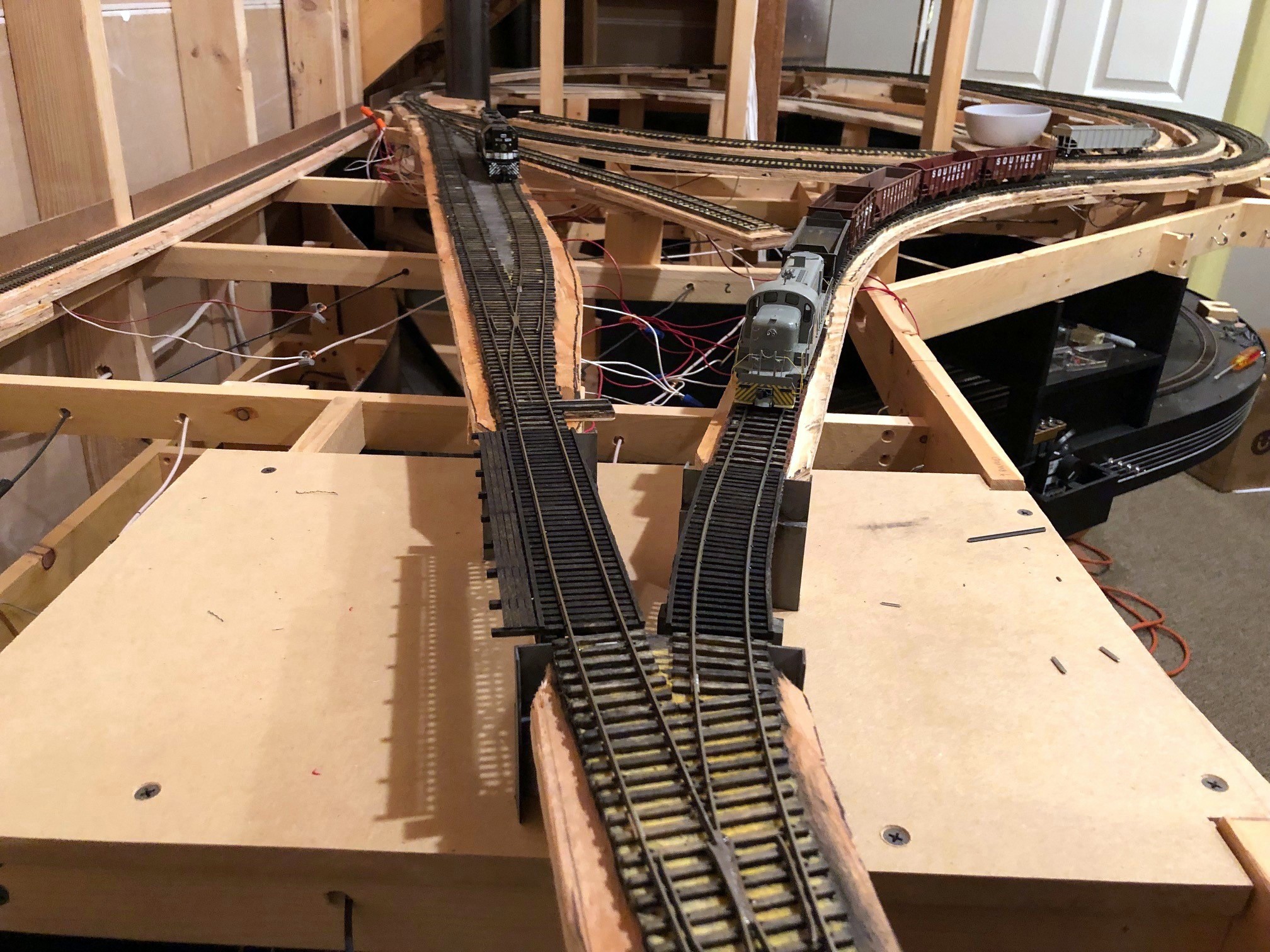
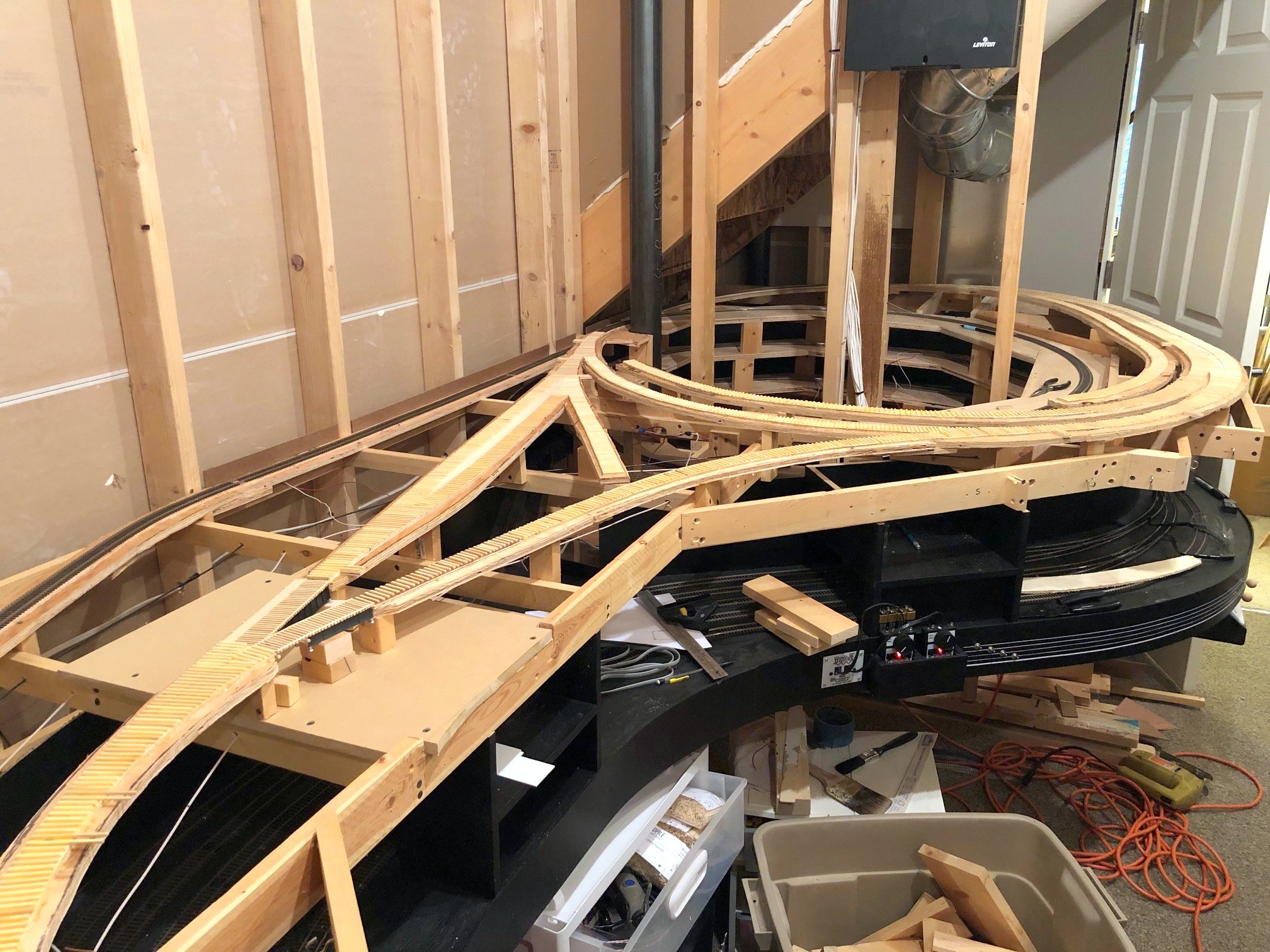
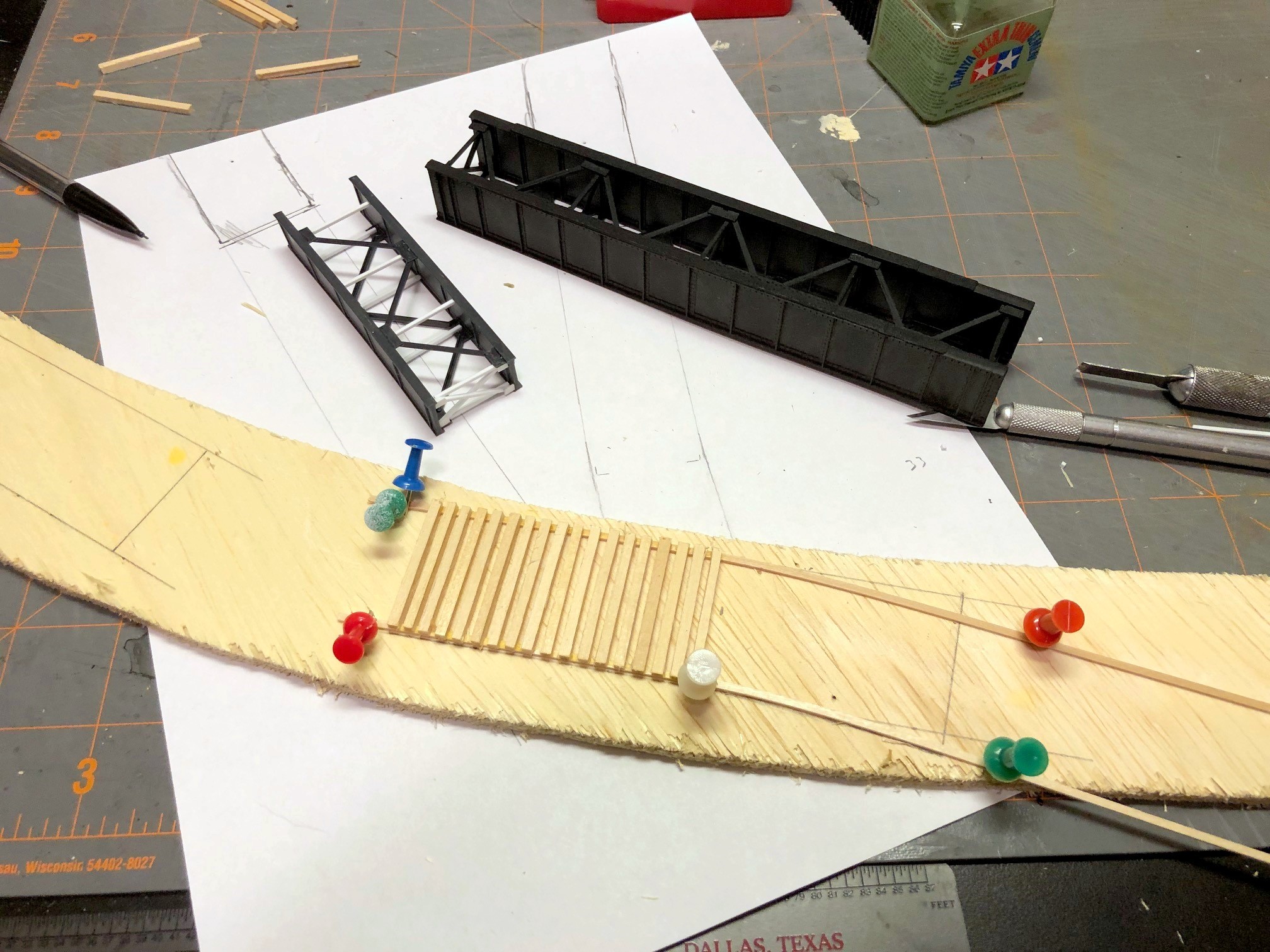
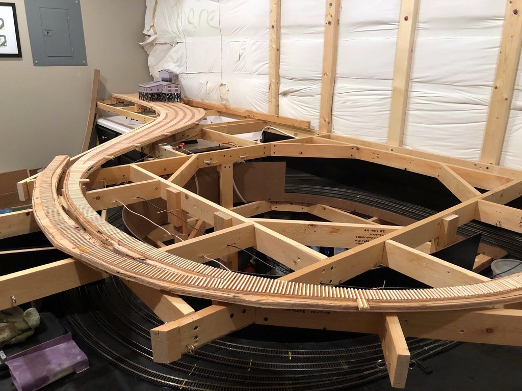
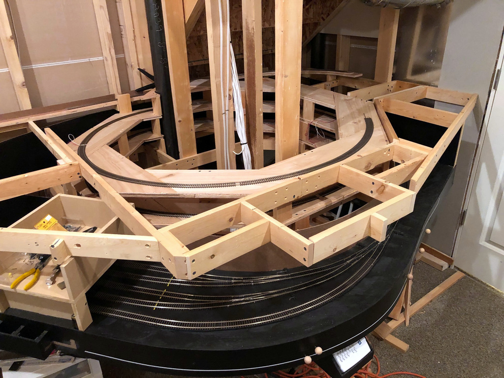
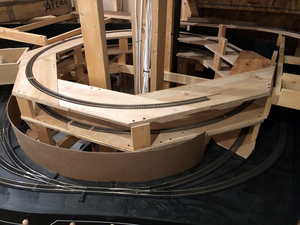
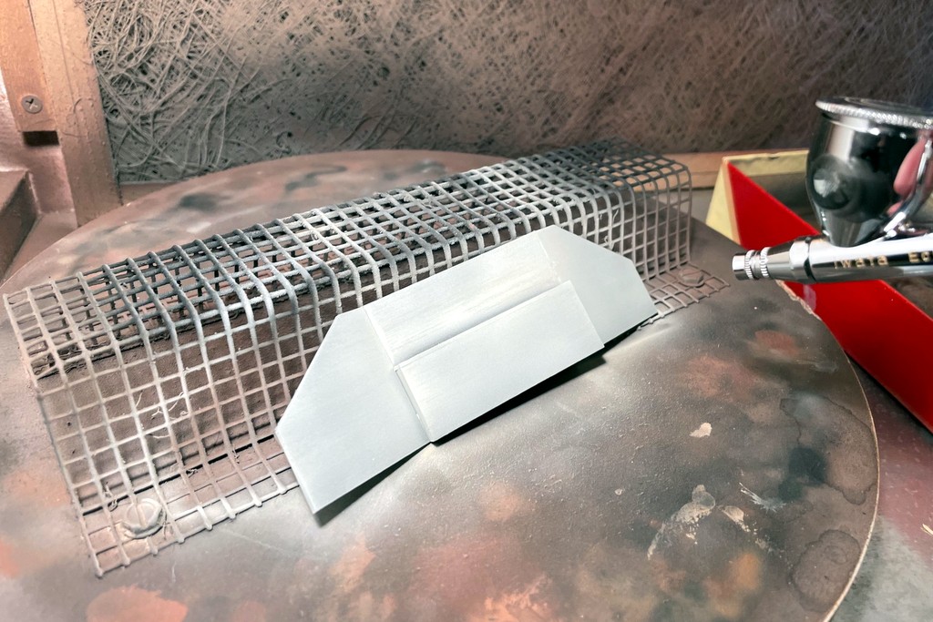
I’ve got four bridges on the upper deck that need to go in before I can lay track, so here’s my walk-through on how I installed the two plate deck girder bridges. I started with two Micro Engineering deck girder bridges, a 30′ and a 50′. I built them according to instructions but omitted the ties (or concrete) that go on top of the bridge because I planned to build my own out of basswood to go well with the rest of the hand-laid track. I sprayed them flat black with an airbrush.
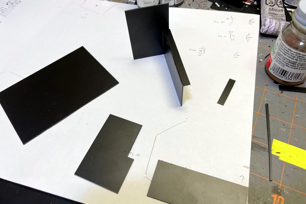
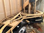
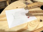
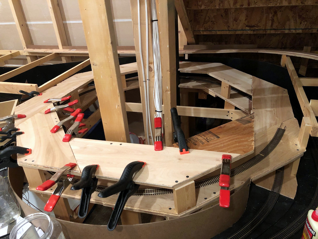
The most challenging part of these builds was the abutments. You have to build the abutment just the right height and size or your track won’t work well. I started by cutting out a section of the subroadbed where I wanted the bridge to go–I just set the bridge on top of the subroadbed, marked it with a pencil, added a scale 6″ or so to both sides to account for the abutment, and cut it with a circular saw. Next, I installed the basic creek bottom with plywood to get a firm foundation. Then I made tracings of the end of my subroadbed where I’d cut the section out and marked the height of each side to the top of the subroadbed on a piece of paper. Next I sketched the basic shapes of the abutments made from looking at images on Google Earth. I also used the ruler tool in Google Earth to get some basic dimensions for the width of the abutments and the length of the “wings.” In this case, each of the bridges has one “normal” abutment that is rectangular and a few feet deep and one “snaky” abutment with wings that extend at different angles rather than going straight back along the tracks. All of the abutments have a central section about 18-20 scale feet wide that goes between the bridge and the ground, and this section has is stepped to provide a base for the bridge feet. I made my central sections 18 scale feet with with an 1.5 scale foot wide step for the bridge feet. The elevation of the step depends on the bridge type, so I just marked the total height of the bridge and foot against the height markings on the paper to get my basic design.

I cut the abutment pieces from .040″ black sheet styrene, and I angled the tops of some of the wings (eyeballed until they looked about right). I added pieces of .020″ styrene to the back side of the abutments to make them look thicker and glued and sanded the pieces to look like a single piece. Before gluing the main pieces together, I took a piece of course sandpaper, held it down with a wooden block, and rubbed the abutment pieces and back and forth using the wood block as a guide to get horizontal lines scratched into the face of the plastic. This gives the “concrete” a rougher look and simulates the grain from using wood forms to build the prototype. When this step was complete, I assembled the abutments using styrene cement and filled in any gaps with model putty which I shaped and sanded when dry. I was able to assemble some of them before the “scratch treatment,” but anywhere I had an interior joint (90 degrees or less), I scratched the pieces first because otherwise it’s nearly impossible to do once assembled.
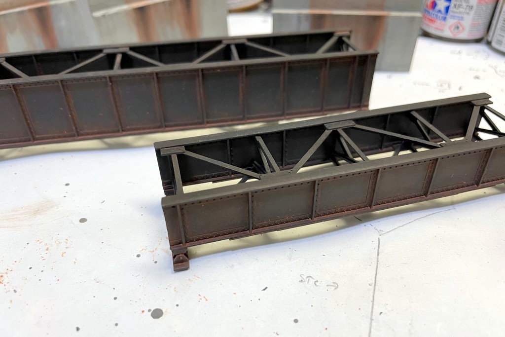
Next I painted the abutments with an airbrush and thinned Tamiya “Deck Tan” paint. The deck tan is a nice gray-tan color and dries very flat. I made sure to spray at least the tops of the insides of the abutments too because they’ll be sticking out above the scenery. I also used some of the deck tan color to lighten the bridges and fade them a bit. I weathered the bridges and abutments using a combination of flat black and light rust colored washes. The entire bridge inside and out got a couple coats of the light rust wash–I left the wash on and set the bridge upright to get the rust to concentrate on the bottom of the panels. All of the abutments got 2-3 liberal washes of flat black. I targeted the rust washes to the areas behind and under the bridge, wiping the wash down to simulate rusty streaks from numerous rain storms over the years. I kept making the wash thicker and thicker and applied it to a smaller and smaller area to get thick streaks just under the bridge feet. I dry-brushed some black in these feet areas as well to darken the streaks and dry-brushed a few more streaks vertically down the walls. Finally, I used some Tamiya weathering powders to add a few more black streaks and white blotches.

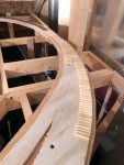
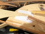
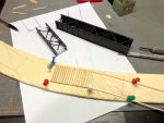
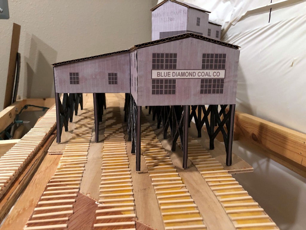
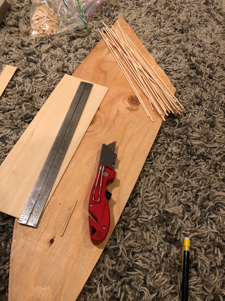
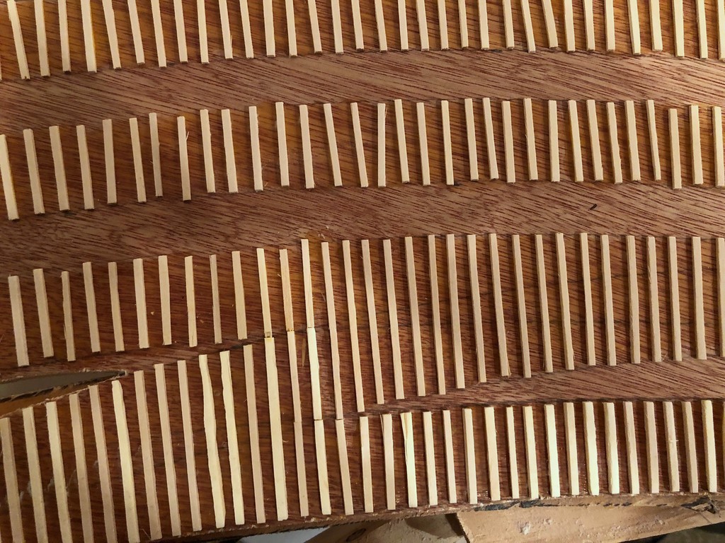
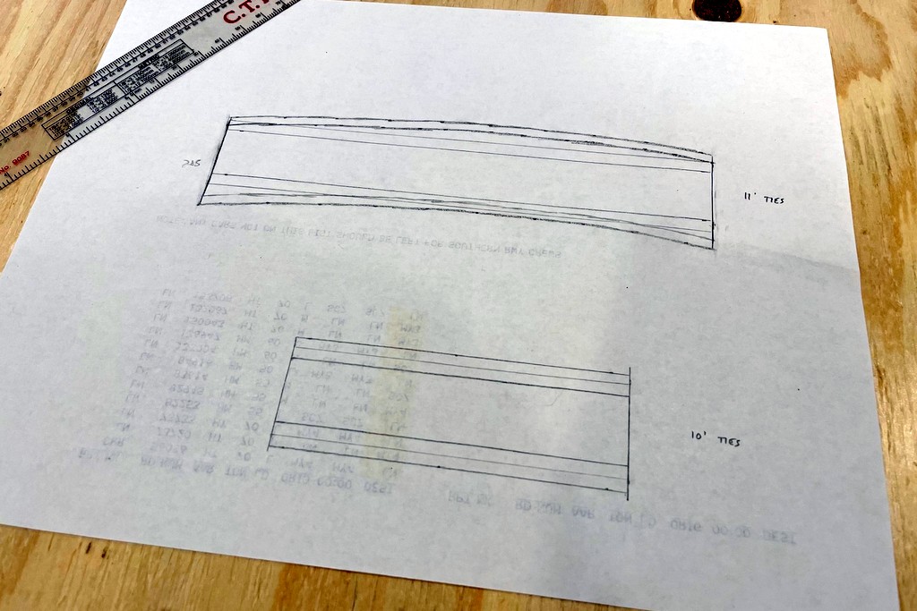
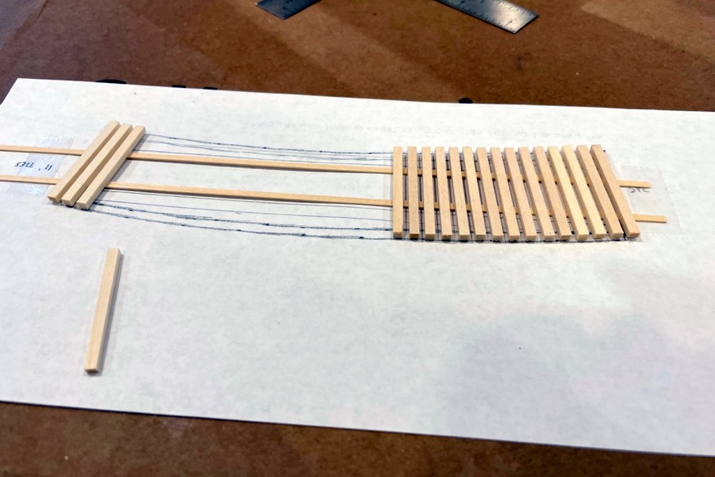
Next I made the decks. The 30′ span was easy because it was straight. I simply drew a scale 30′ x 10′ rectangle as my template, cut a few dozen scale 10′ sections of scale 8×10″ basswood using a Northwest Shore Line “Chopper”, laid down two strips of scale 3×6″ basswood along the edges of the template (slightly in from the edges), and laid the ties onto these strips one-at-a-time using small drops of Elmers white glue. I use white glue because it’s easy to work with, does the job, and seems to take stain slightly better than wood glue. The track over the 50′ span is on a 24″ radius curve, so it took a bit more work. For the template, I traced the bridge, then used my 24″ radius template (a plywood cutout) to mark a track centerline on top of the bridge outline, making the line about equal distance from both bridge sides (as measured at the ends of one side and the middle of the other side). Standard bridge ties are about 10′, but with 24″ radius that wouldn’t quite cover the bridge, so I opted for scale 11′ ties and marked an outline on the template 5.5 scale feet from the center line on both sides. To make sure the ties held the right curvature, I laid these ties on top of two strips of scale 3×8″ basswood laid straight so they would fit inside the bridge panels. I pinned these down with tacks on top of the template, then laid the ties one-at-a-time using the curved lines I’d drawn. Once this dried, I flipped it over and laid the 3×6″ edge boards using tacks to curve the boards until they dried.
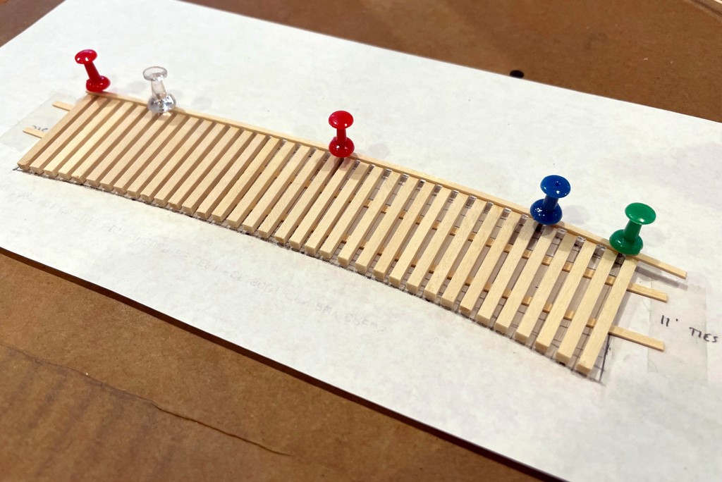

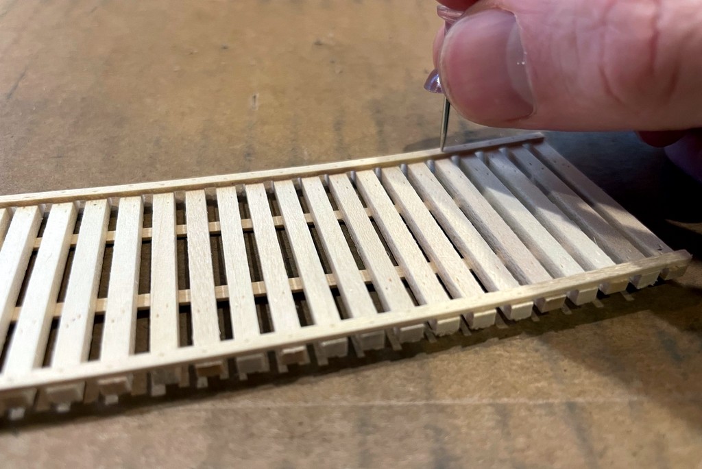
I gave the decks a little more detail by adding some nail/bolt marks using a thumbtack. When stained, the tack mark shows up extra dark and gives the illusion of a nail/bolt without having to install hundreds of castings. I put a bolt hole in the edge board over each tie, and I put four offset bolts in each tie over where it would attach to the girder underneath. I use a ruler to make sure each line of bolts is straight. This adds some nice detail to the deck, and it’s quite striking to see a line of straight bolt heads against the curvature of the rail on a curved bridge. I finished the decks by staining them with Minwax “Ebony” stain, dabbing up the excess with a paper towel, and letting them dry.
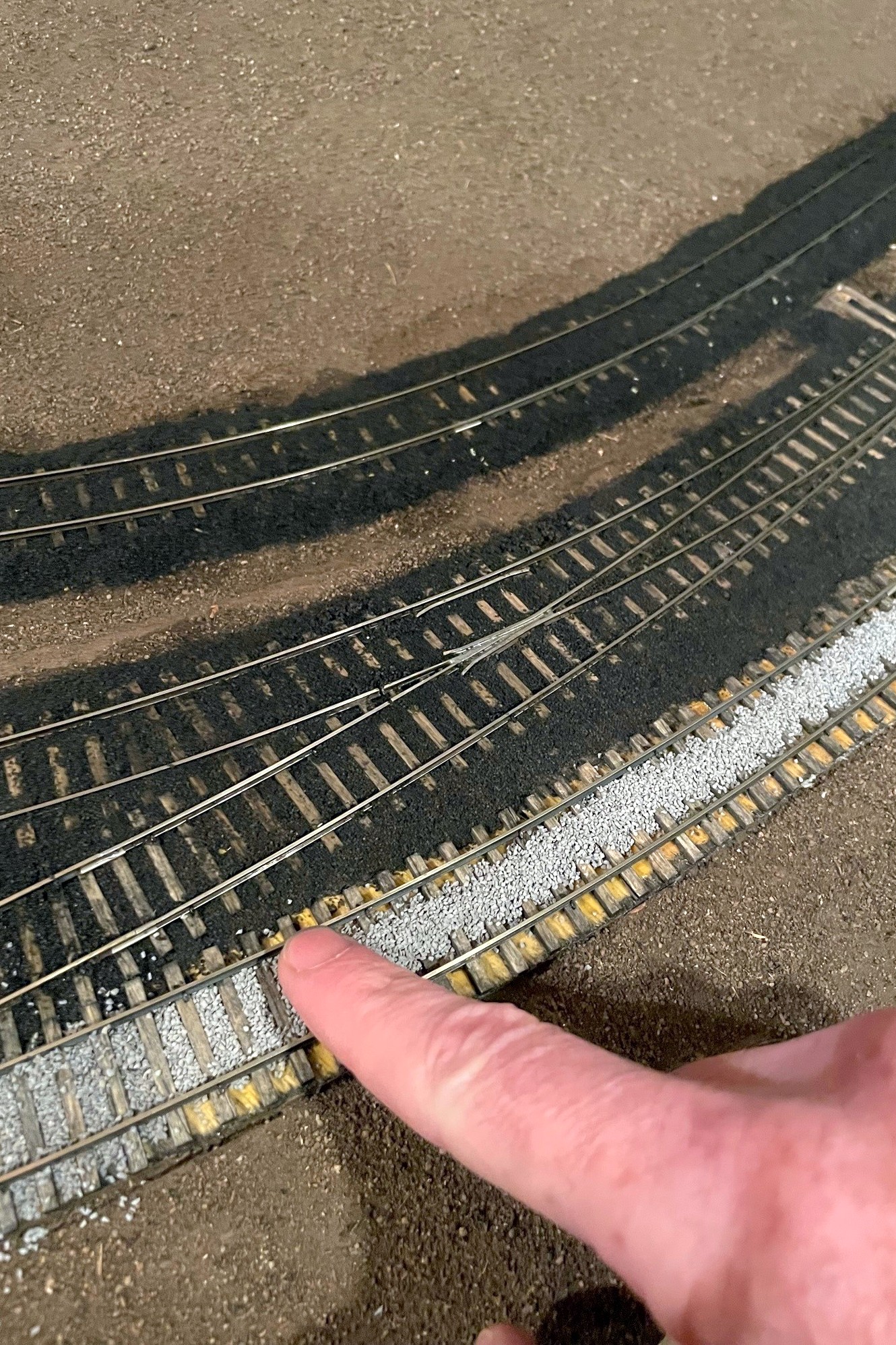
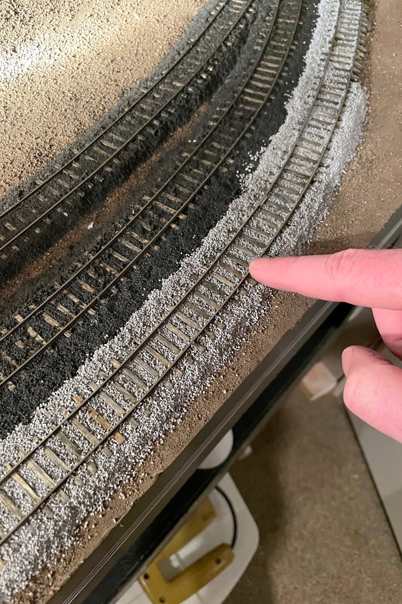
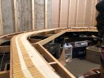
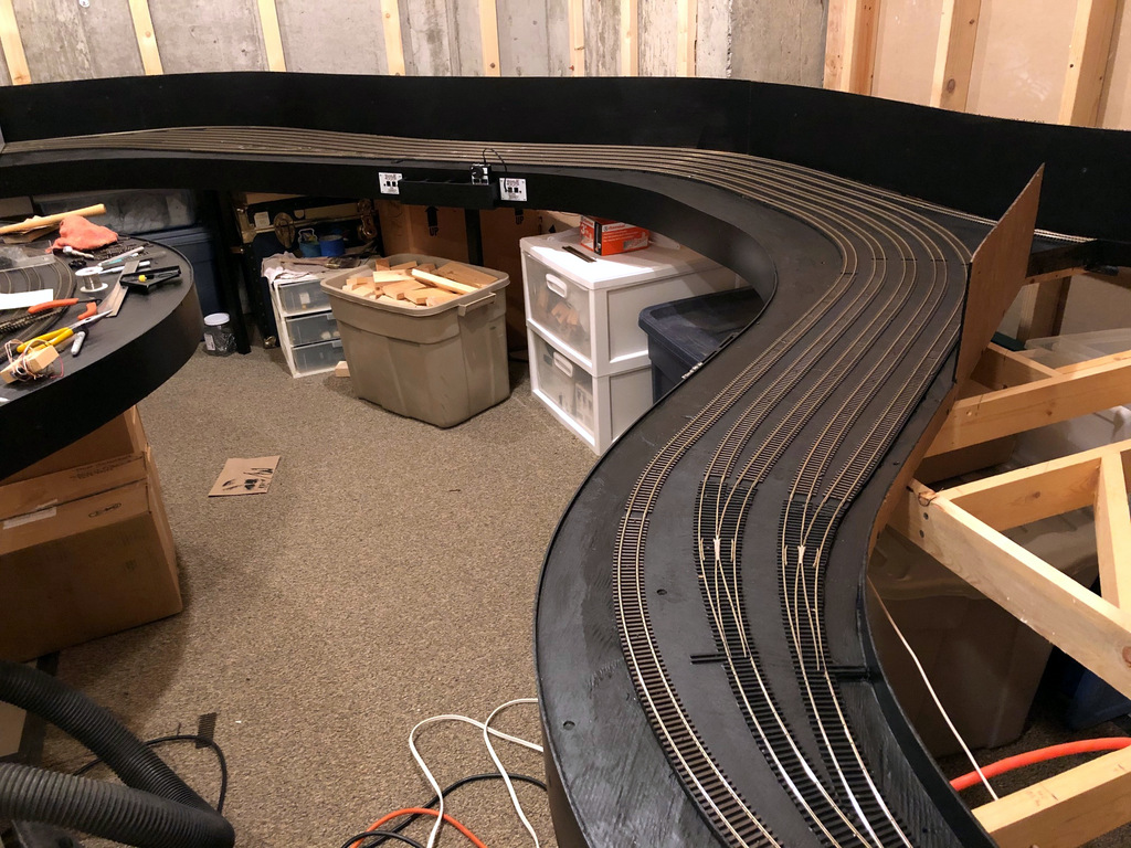
Now I had all the pieces to install my bridges! I waited until I’d finished the sanding and staining of the adjacent track ties as this would have ruined the abutments if I tried to do it with them installed. First, I test fit everything to make sure my bridge ties were at the same level as the adjacent ties. If not, I either sanded a bit off the bottom of the abutment (difficult) or added some thin pieces of styrene to the bottom to get them to the right height (easier). Lesson learned: when in doubt, make the abutments slightly short and shim them up–the base will be covered by scenery, and it’s a lot easier to add then remove at this point. With the heights correct, I then test fit the entire bridge structure and moved the pieces around until I was happy that 1) the bridge was in the right spot, and 2) the abutments were centered on the bridge. When happy, I used a pencil to mark the corner positions of the abutments onto the plywood beneath and removed everything.
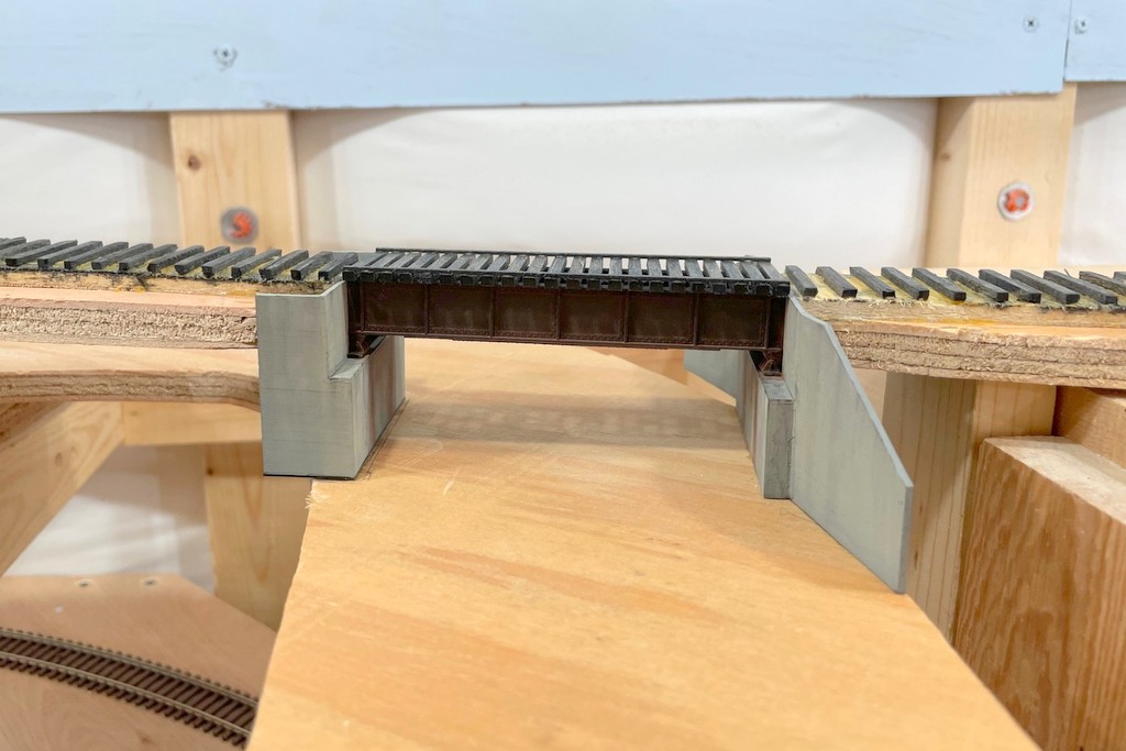

I applied some Pliobond adhesive to the bottom of the abutments and the portions of the abutments that would touch the adjacent subroadbed and set them in their marks on the layout to dry. Next I used some Pliobond on the bridge feet and carefully set the bridge in place on the abutments. Once dry, I used a little Pliobond in lines on the bottom of the bridge tie section and set it in place on top of the bridge. Once happy with the alignment with the adjacent ties, I set a couple blocks of wood on top to help it all dry flat and level.
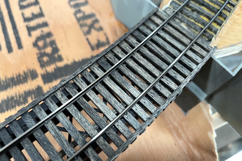
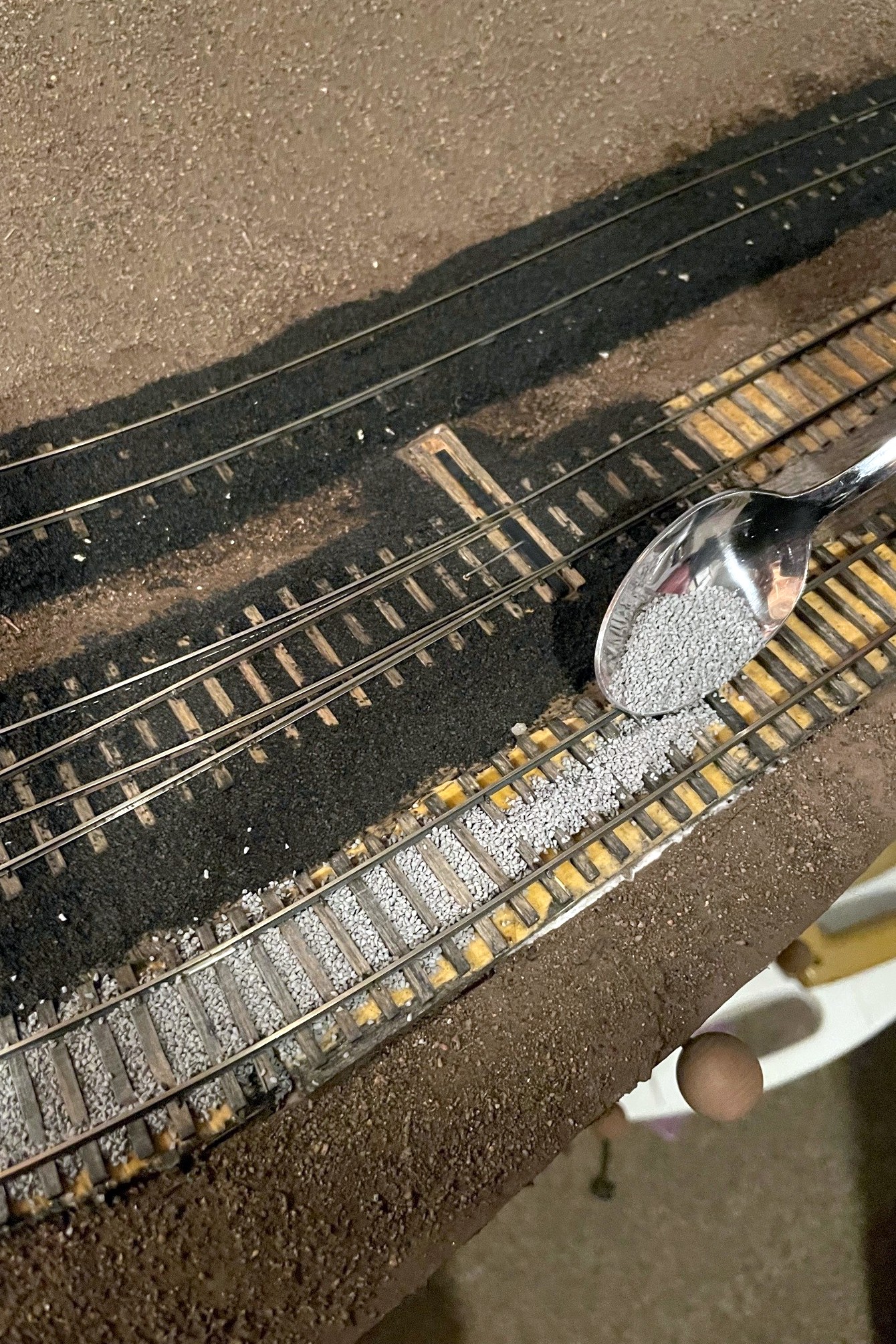
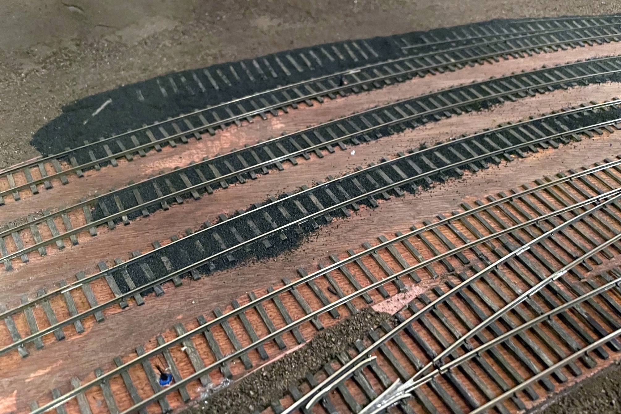
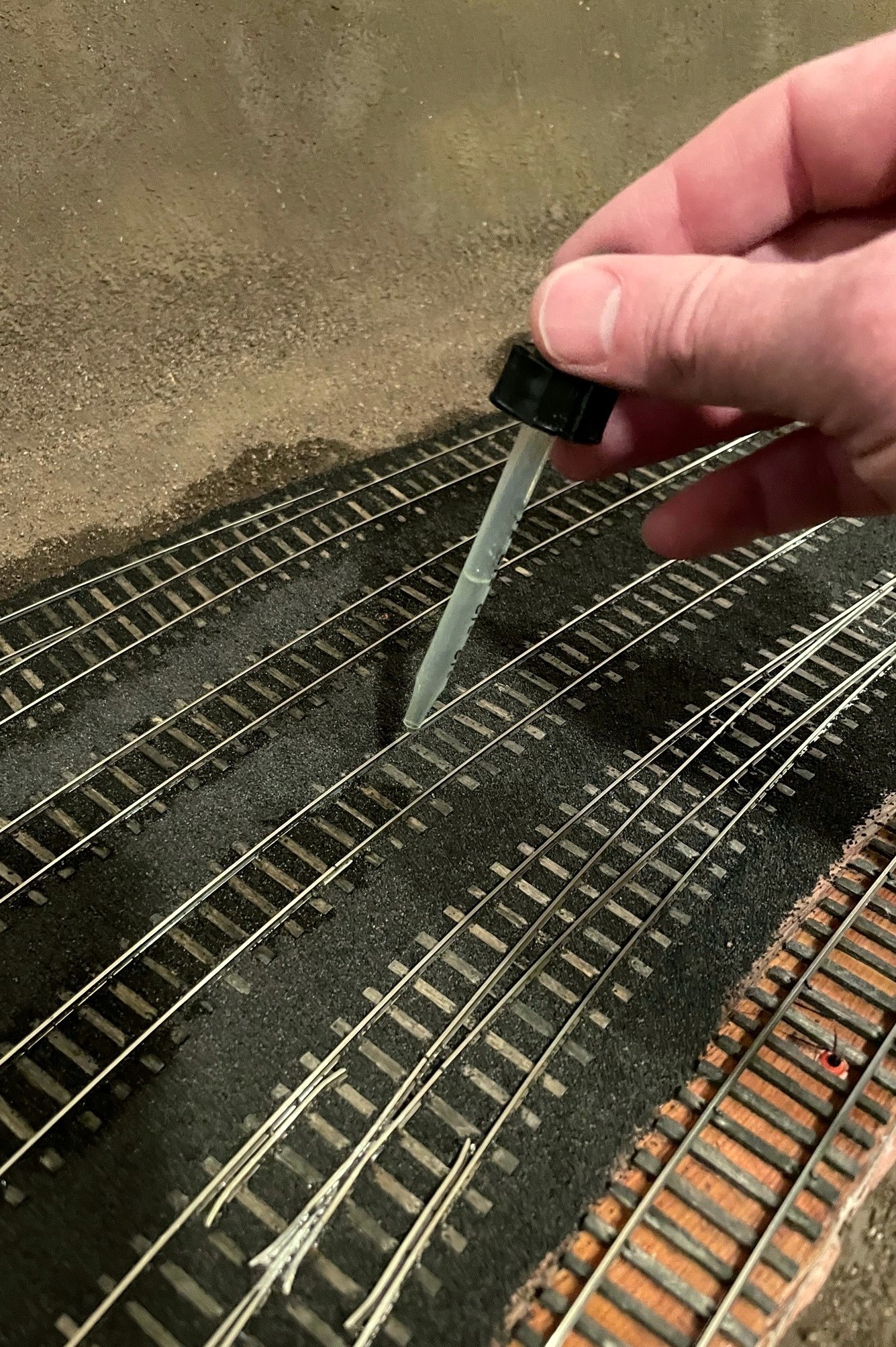
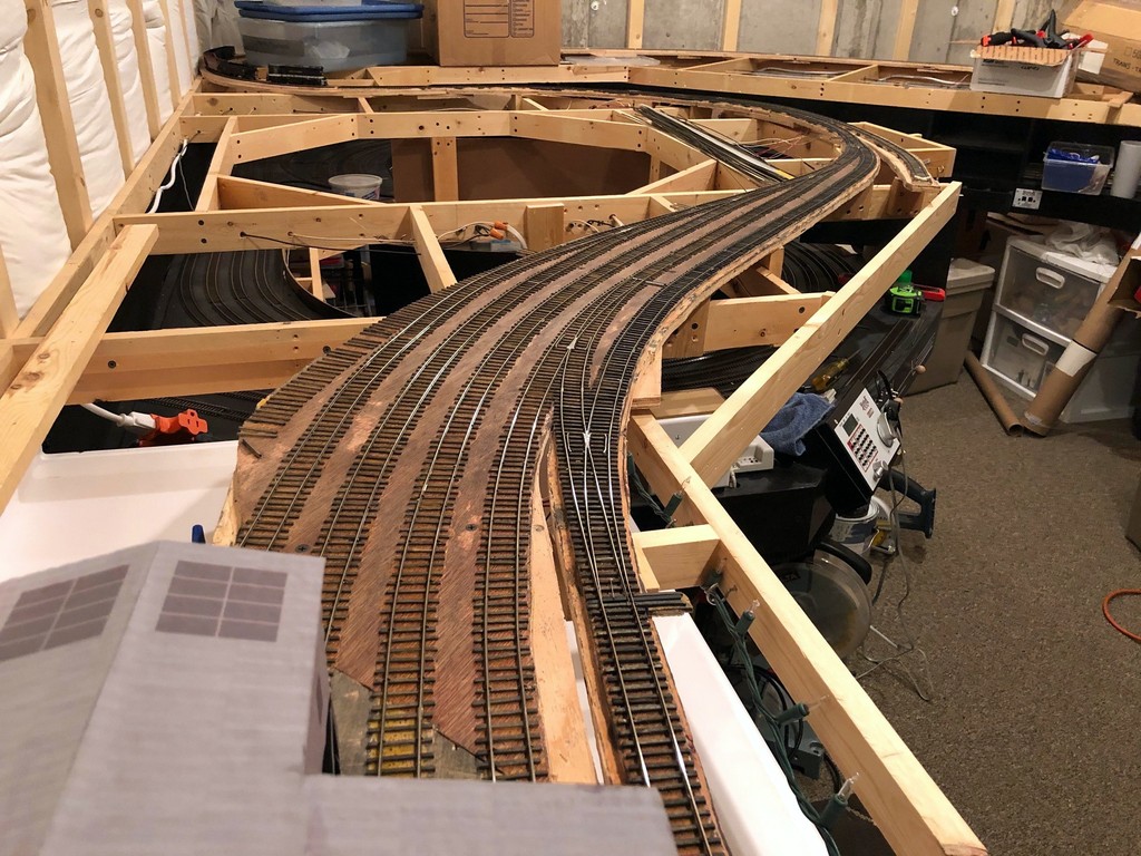
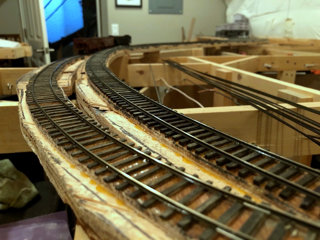
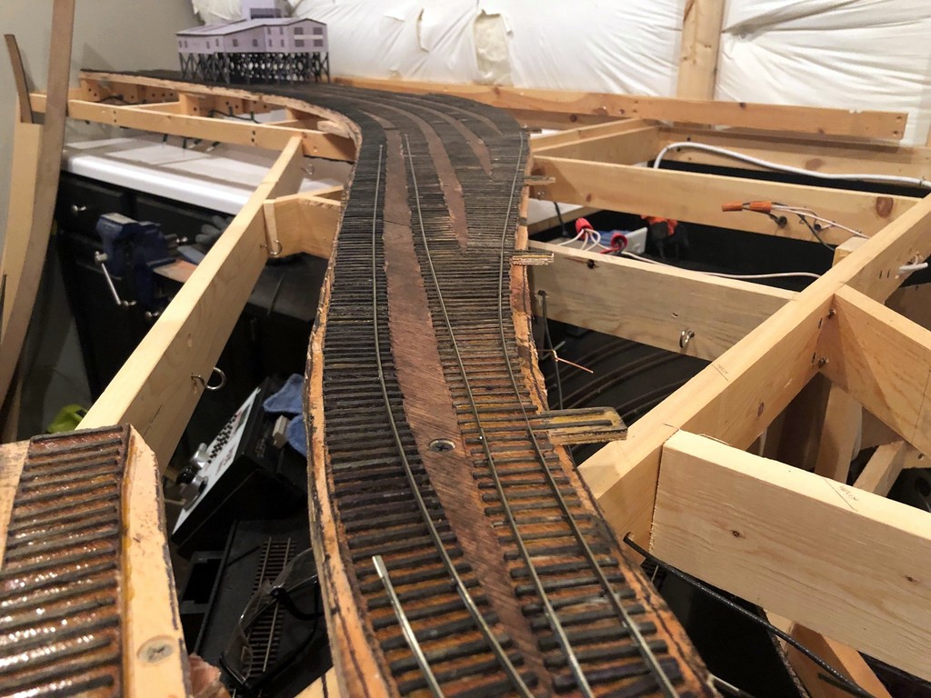
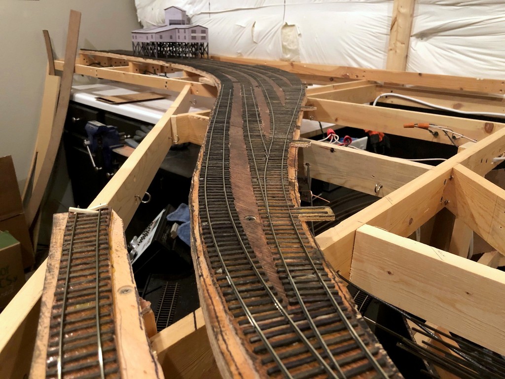
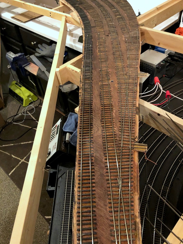
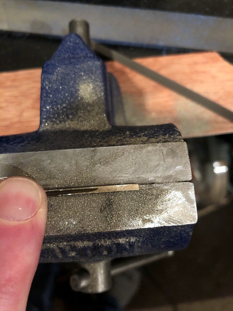
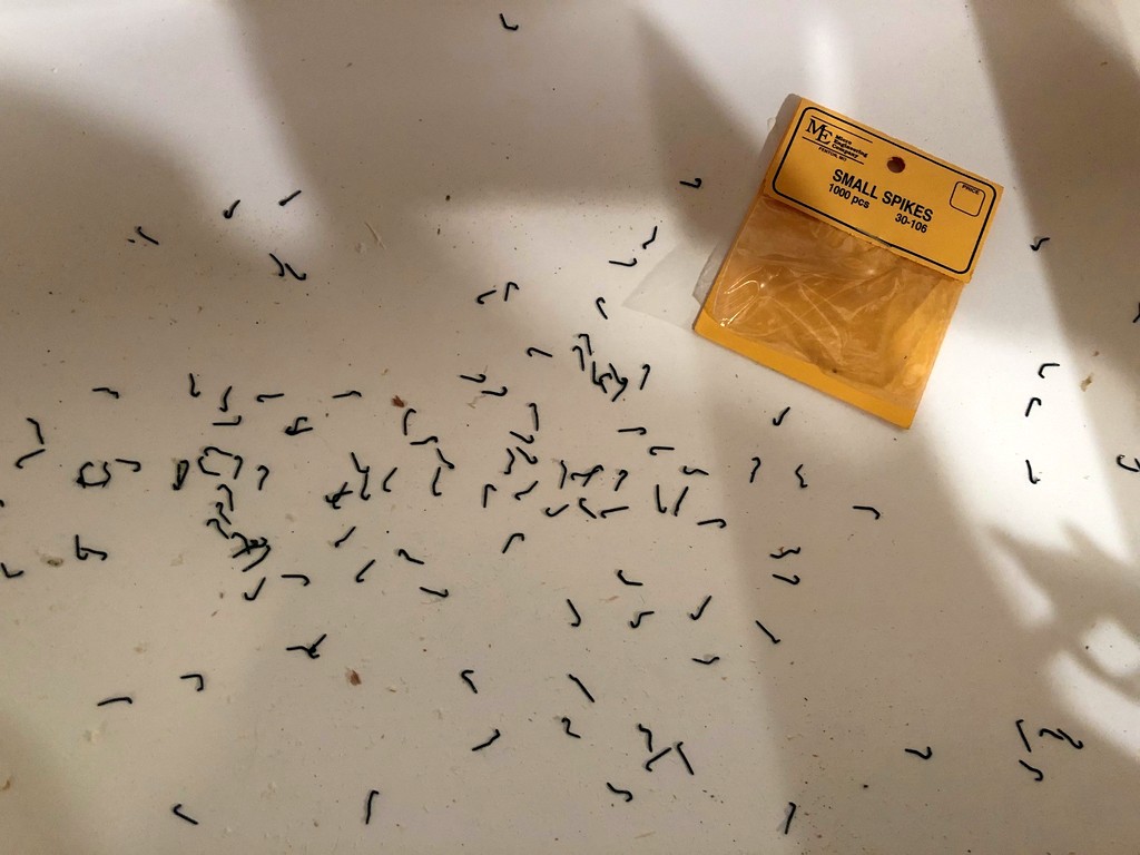
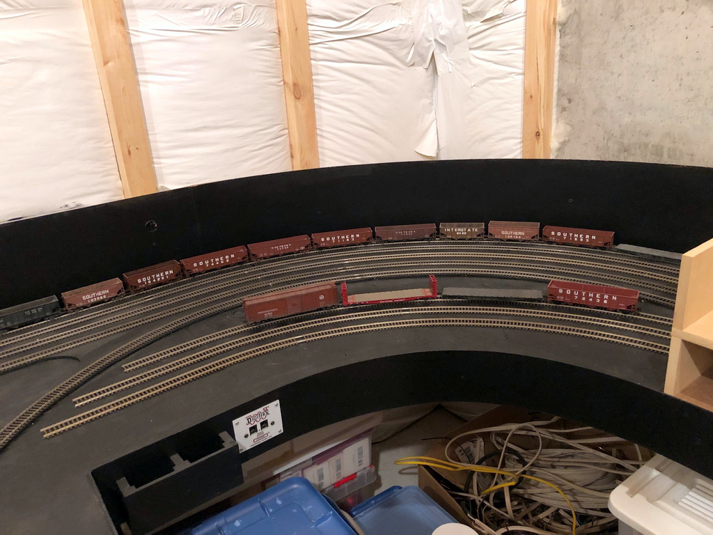
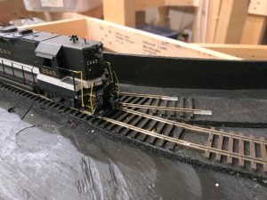
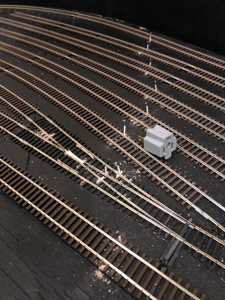
The final step was adding the rail. I just ran the long rails over the bridge just like the other ties and spiked the ties adjacent to the bridge. I used Micro Engineering “micro spikes” on the bridge (I use “small spikes” elsewhere). Since the spikes were slightly longer than the ties are deep, I used a No 79 drill bit to predrill the spike hole, especially where the spike would go into the plastic bridge. I spiked about every fifth tie. A look at prototype photos doesn’t reveal any guard rails, so I omitted them on my models as well.
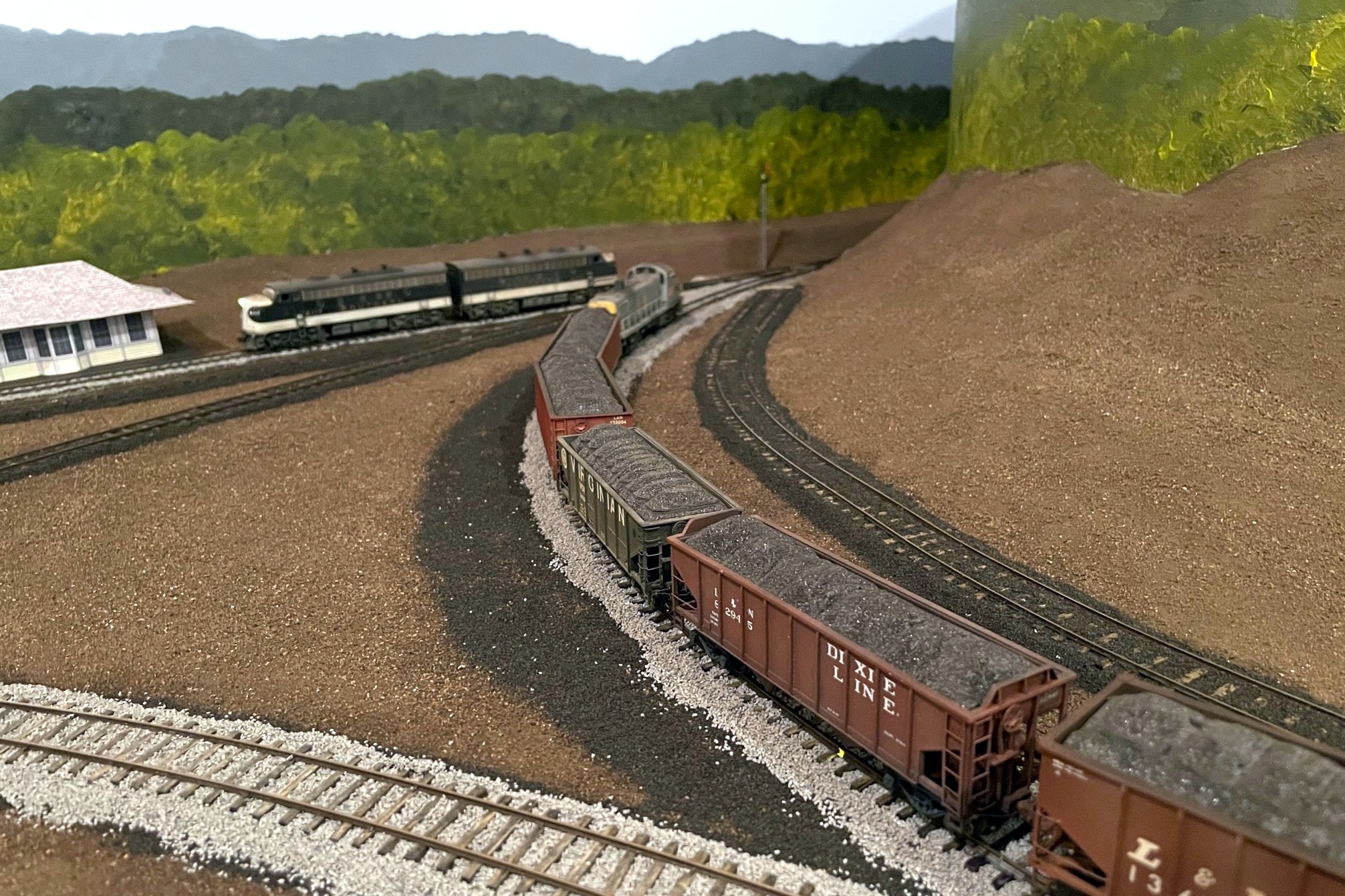
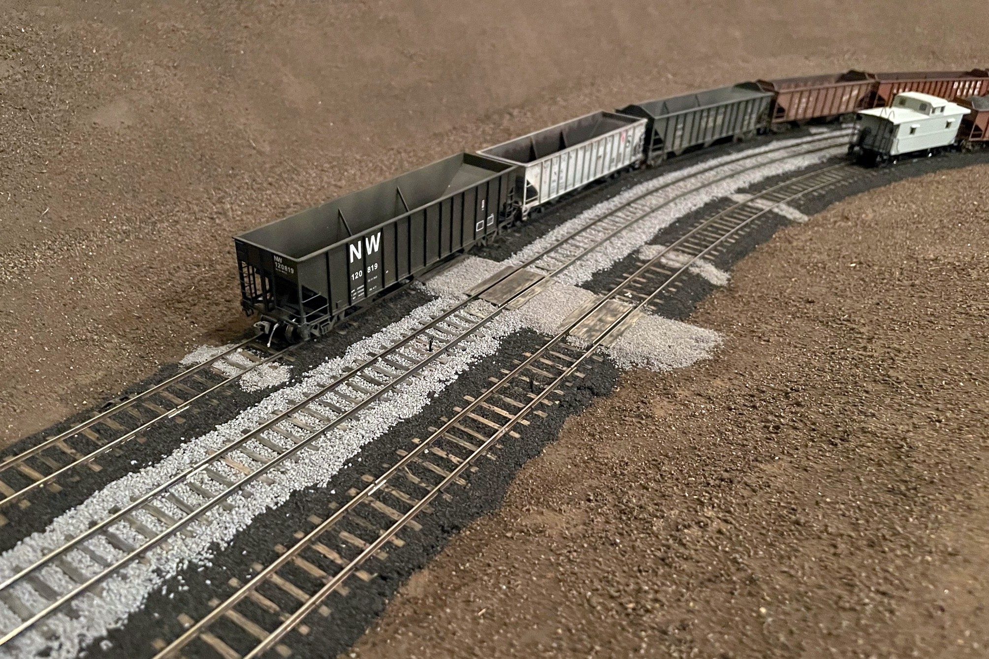
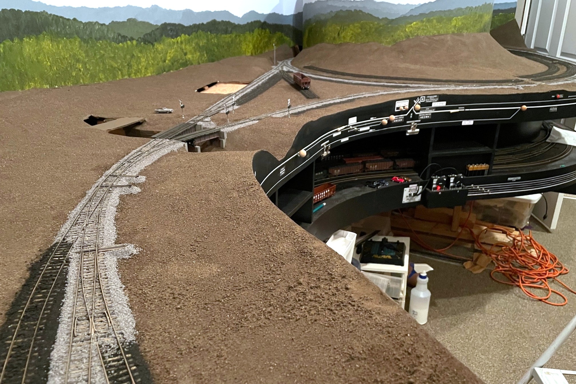
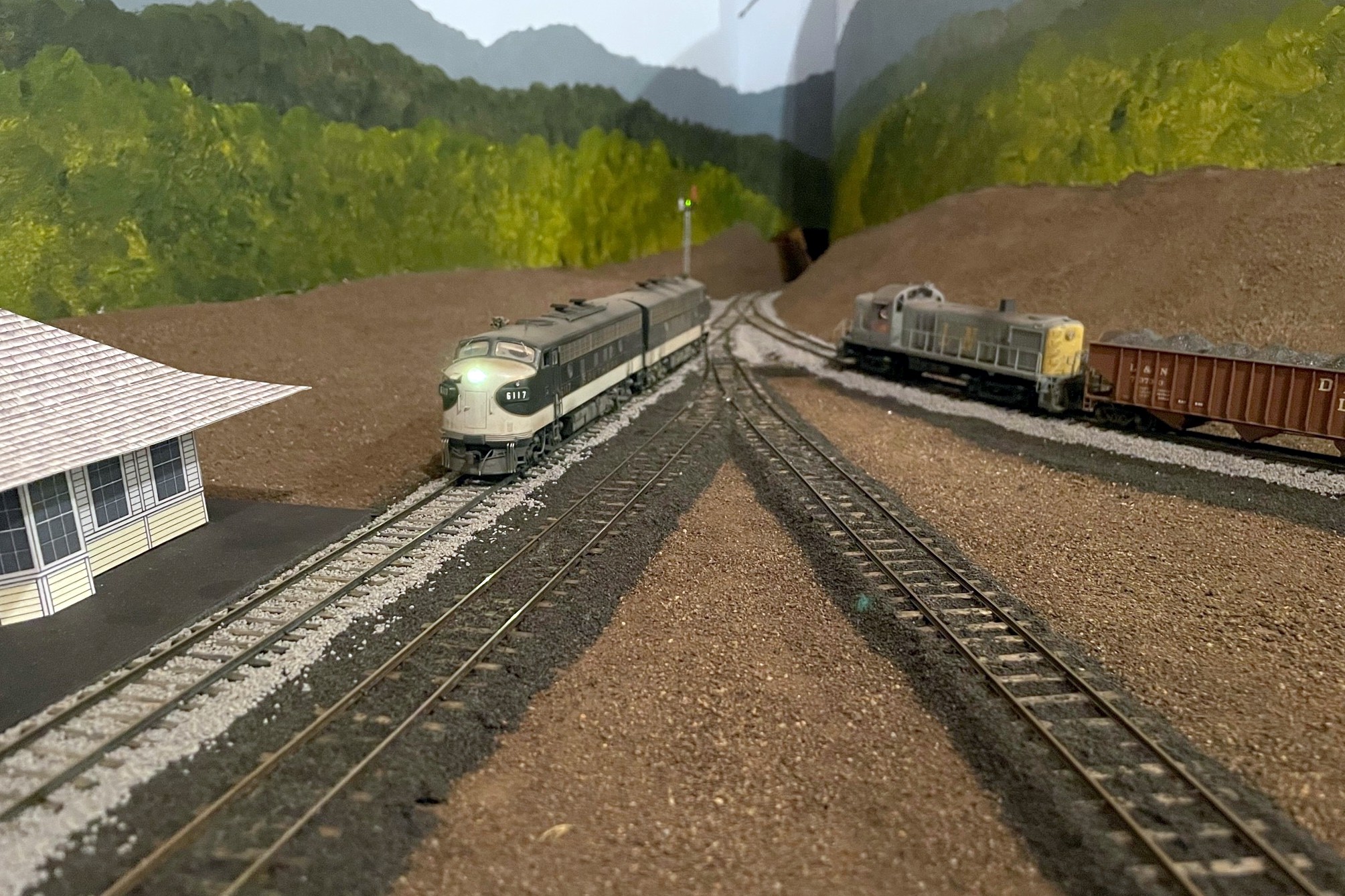
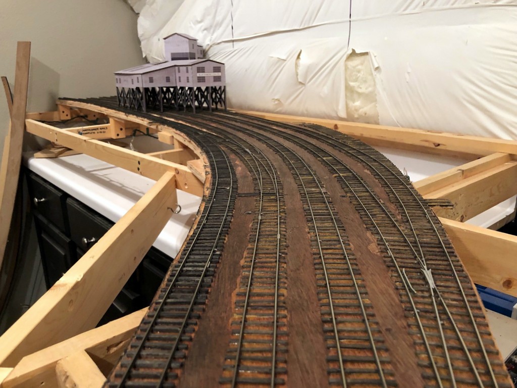
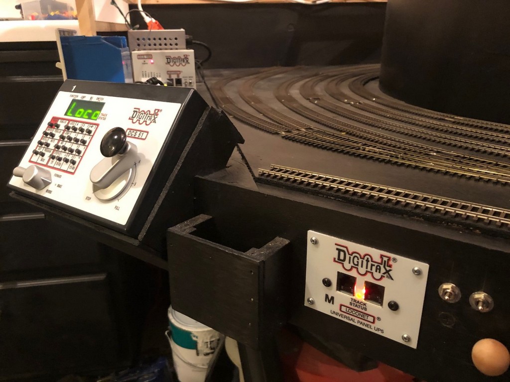
That’s it–bridges installed and now handling trains!