As I’ve stated in previous posts, sound decoders have drastically changed my approach to DCC consisting. In an ideal world, I want all movement controls (forward, reverse, braking, dynamics) within a consist to be controlled by a single throttle, and I want only the lights, horns and bell of the lead unit to respond when an operator selects these functions. Digitrax’s “universal consisting,” unfortunately, doesn’t allow function-controlled movements like braking to go to the entire consist. Also, if you reverse the direction of the consist, you have to rebuild the consist to control both movement, lights and sound with the new lead unit. This is not a big deal for trains that only run in one direction, but every single one of my trains is an “out and back” where the lead unit of a consist switches, sometimes several times in a session. Asking operators to rebuild the consist every time they switch the train’s direction is not ideal.
Moving to “advanced consisting” (decoder-aided consisting) solved many of these problems but not all. Using the “consist” tab in JMRI, I was able to use the directional lighting features built into my Soundtraxx Tsunami 2 decoders to set the lights on the end units in a consist to “respond to consist address” but only in forward or reverse, thus solving the challenge of only getting the end lights in a consist to illuminate. The horns and bell, however, cannot be set to only operate directionally using the consist controls, so I was stuck with picking one loco in the consist to respond to all the horn and bell commands… this works, especially if all units use the same horn type, but it bothered me a bit to hear a Nathan M5 from the trailing GP35 instead of the Nathan P3 from the leading GP38. When I posed this question to a group of Digitrax experts, one of them pointed me to this video from Soundtraxx where someone had figured out how to use “alternate sound levels” function in the Tsunami 2 decoders to get directional horns, so I had to give it a try. The video left a few steps out, perhaps because they were using “simple consisting” (same address), so I had to experiment a bit to figure out how to make it work with advanced consisting, but in the end, I was able to get the consist to perform [almost] exactly as I had hoped using the following method.
The Gist
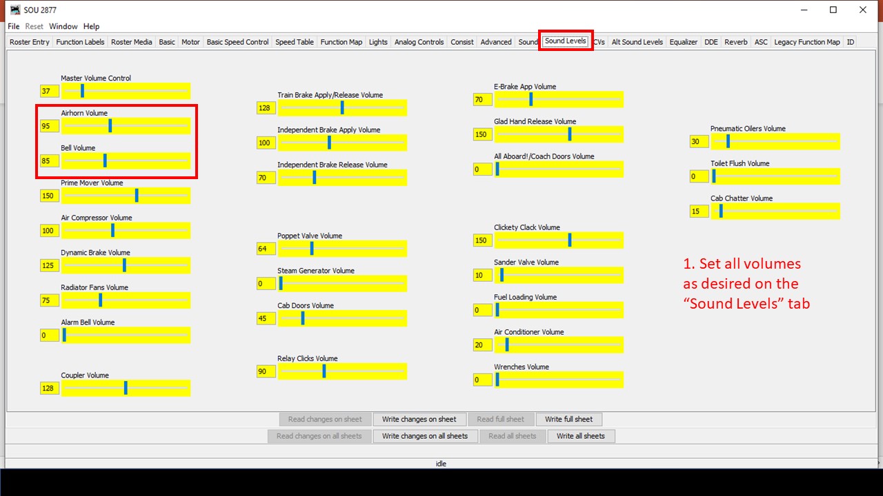
Soundtraxx Tsunami 2 decoders have an “alternate sound mixer” designed to make it easy to select a new set of alternate sound levels with the press of a function button. Additionally, the “function mapping” in Tsunami 2 decoders allows you to set any function to operate automatically when the command station commands the decoder in “forward driving,” “reverse driving,” “forward driving,” or “forward standing” conditions. The trick is to set all the alternate sound levels to match the primary sound levels EXCEPT the horn and bell which are set to volume “0,” then use the function map to configure the alternate mixer to operate any time the decoder is moving in the trailing direction (forward or reverse based on how it’s sitting in the consist), and finally to set up the decoder to “respond to consist address” for horn and bell functions. When you set up the locomotives on the ends of the consist in this manner, it has the effect of silencing the horns and bell when the locomotive is trailing and not leading. Here are the steps in JMRI.
Step 1. Set the sound levels in the primary sound mixer
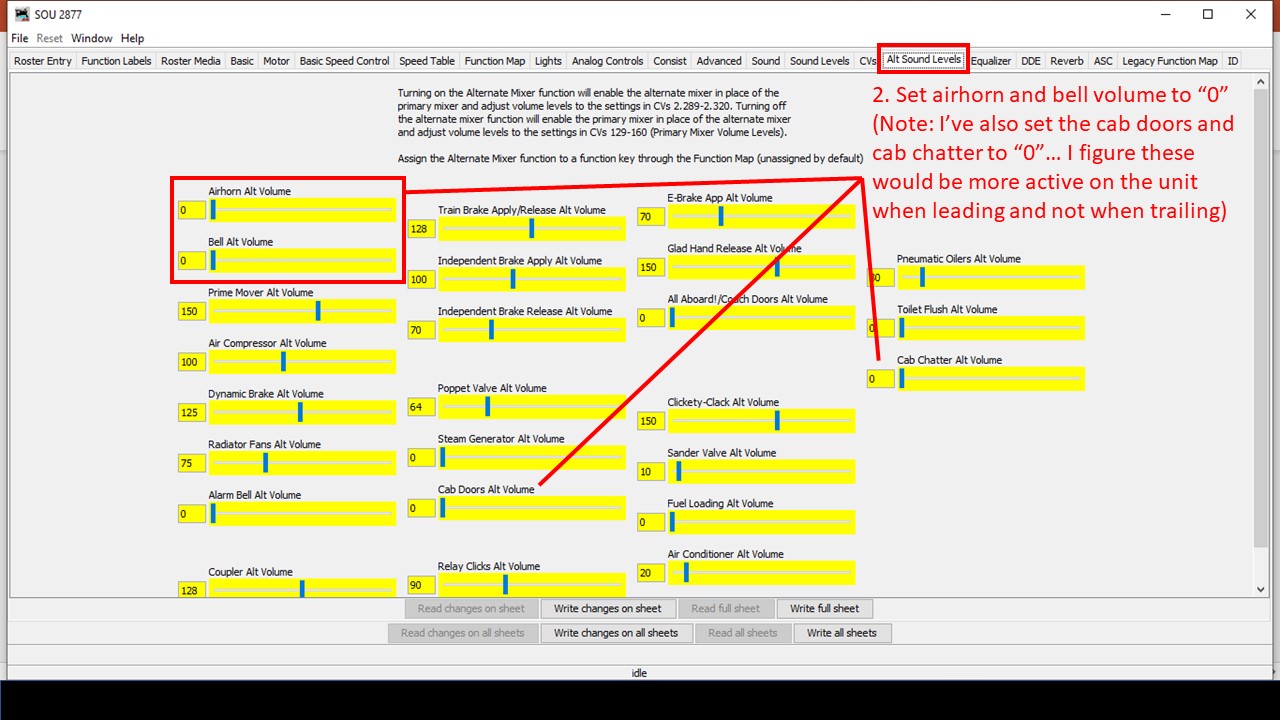
Step 2. Set the horn and bell to “0” in the alternate sound mixer
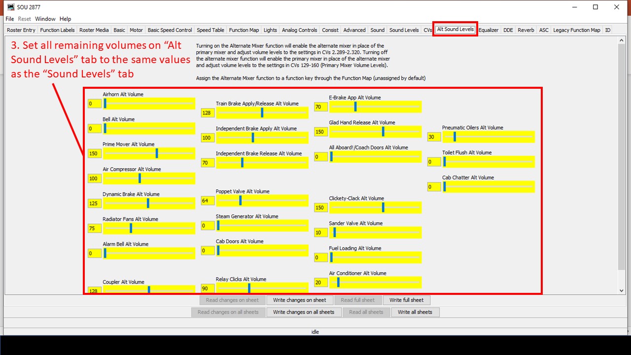
Step 3. Copy all other sound volume values from the primary to the alternate sound mixer
Step 4. Set up the “alternate mixer” to operate with forward or reverse direction (the direction in which it’s trailing in the consist)
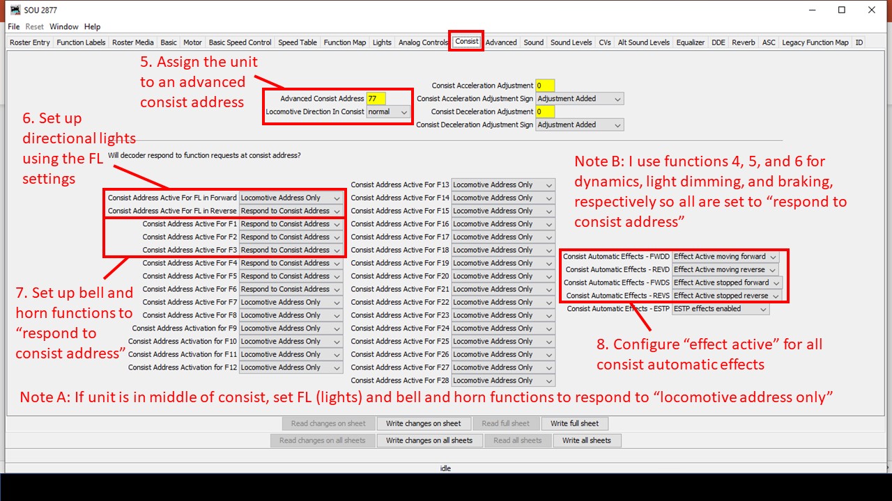
Steps 5-8. Set up the advanced consisting so directional lights and functions for horn and bells “respond to consist address” and enable the automatic functions
Some of the settings will depend on where the locomotive is in the consist and whether or not its on the end. For a locomotive in the middle of the consist, you can either set the decoder’s light, horn and bell functions to “locomotive address only” in the consist tab, or you could place check marks in all four columns in the function map (forward driving, reverse driving, forward standing, reverse standing) so only the alternate mixer with zero volume for bells and horn are used. If you change the orientation of the locomotive, you may need to change the FL settings in the “consist” tab and swap from “forward” to “reverse” check marks in the function map. Also, if you’re using a locomotive on the end that doesn’t support an alternate mixer (like the Soundtraxx Econamis I have in some locomotives), then you’ll need to pick just one of the locomotives to “respond to consist address” to provide the horn and bell for the whole consist and disable the directional checks in the function map.
That’s it! Now when you run a throttle using the advanced consisting address, the lights on the ends will be directional, AND only the horn and bell of the leading unit will respond to the throttle’s horn and bell functions no matter which direction you’re running. Click on the video at the top of the page to see this in action, and if you’ve got some even better tips and tricks for this, please leave them in a comment below!
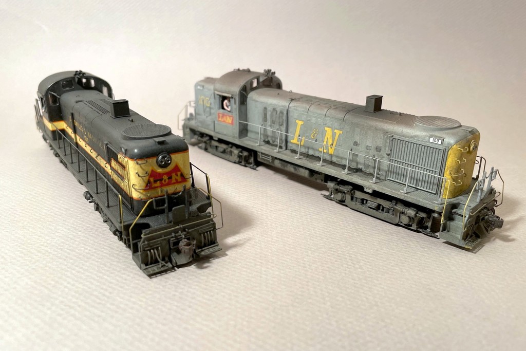
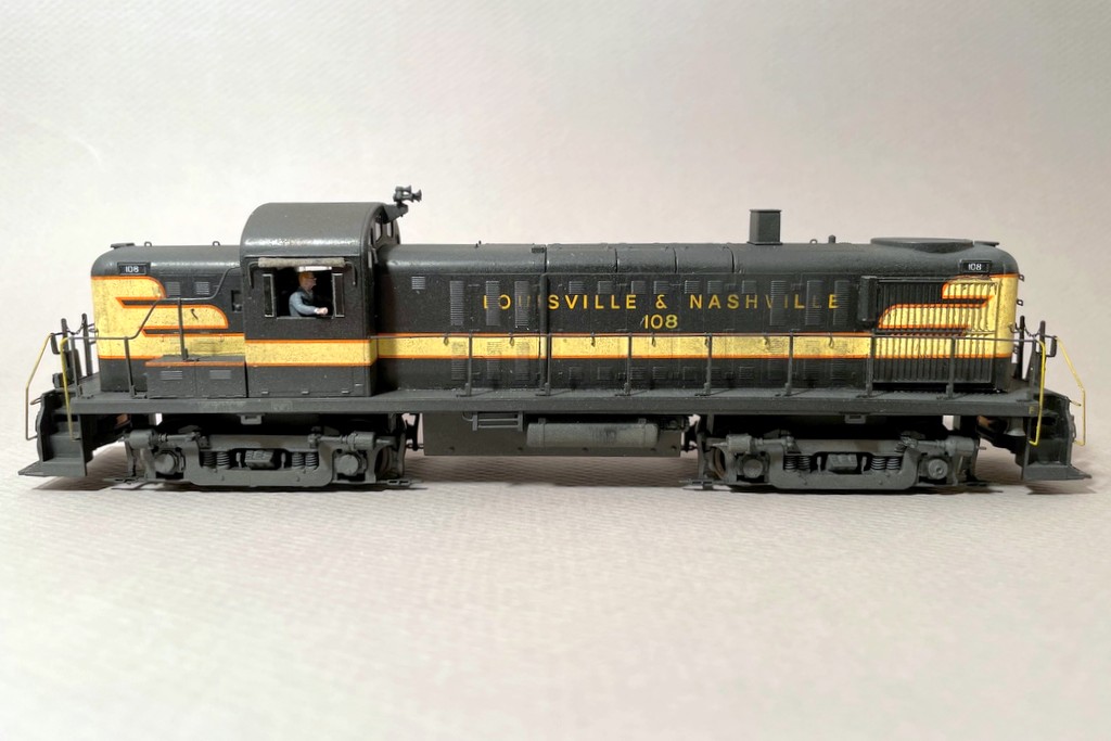
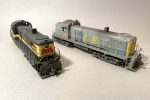
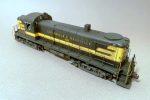
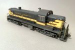
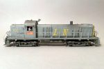
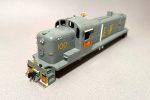
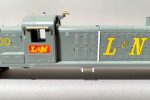
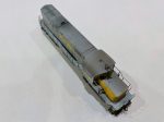
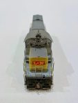
L&N RS3s 108 and 100, highly modified Athearn RS3s in original black and cream and early gray and yellow paint schemes
Standard diesel power on the L&N Cumberland Valley Local (CV Local) that served the St Charles Branch was a single RS3 until around 1974 when they were replaced with a single C420. The RS3 was the quintessential L&N mine run power of the ’60s and early ’70s, and these units sported a variety of paint schemes through the years. While the Phase III RS3s with rectangular carbody filters, prominent number boards and gyralights were more common, the early Phase IIs made regular appearances as well. I picked up two factory painted Athearn models a couple years ago to become CV Local power. I’ve been noodling on them for at least the last year, and the combined Southern Railway Historical Association (SRHA), L&N Historical Society (LNHS) and Railway Prototype Modelers (RPM) meet at Chattanooga, TN in October 2022 gave me the impetus to get these across the finish line.
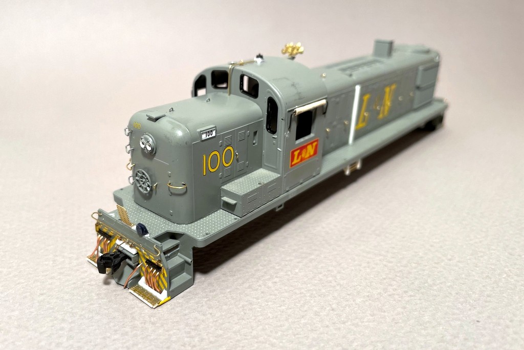
In-progress shot of L&N 100 showing some of the pilot and cab details
The Athearn models are decent, especially the body shape (old MDC shell), crisp paint, and fine handrails. The detail level, however, especially on the pilots, left a lot to be desired. I ended up scratchbuilding a ton of parts for these models which was actually a lot of fun and very rewarding! First things first, the black locomotive came as 102, and it had the original parallel exhaust stack these units were delivered with. I wanted 108 because it actually served as CV Local power in 1964 still in its original paint, so I scraped off the “2” on the long hood, scraped off the number-board decals, and replaced them with Microscale numbers from an L&N set. I also replaced the stack with a transverse stack from a spare shell and filled the old holes. For L&N 100, I “faded” the red L&N herald on the cab sides with a little wet sanding to make it look as though the red paint was wearing off and leaving the yellow underneath, something evident in many photos.
On the body, I scraped off the hood-door latches and replaced them with pieces of bent wire. I added some scratchbuilt lift rings to the long hood as well, and I bent new long grabs to curve around the hood ends as the factory grabs did not adequately capture their curves. I replaced the factory horns with some Overland 5-chime forward Nathan M5s as the factory horns were either incorrect or oversized. For unit 100, I scratchbuilt the antenna conduit and base from brass wire, eye bolts, and styrene with a DA whip antenna on top along with a scrap round cab-top vent from the scrap box. I also scratchbuilt the oil cooling coils under the right side (long-hood forward) from wire and styrene, and a piece of styrene rod completed the piping along the right side of the hood. The L&N units also had a rectangular hole below the third step on all corners, so I carved this out of the shell by drilling holes and cutting out the rectangle with a sharp X-Acto blade.
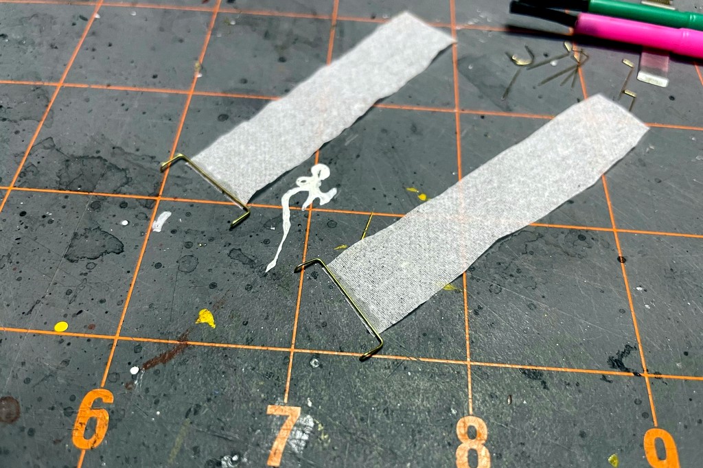
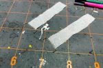
Step 1 of canvas sunshades is to bend the rod and attach a piece of tissue paper
One fun detail was the cab sunshades. The L&N used simple canvas sunshades that rolled around a bracket. My friend Stuart Thayer showed me years ago a canvas radiator cover for a switcher he made from tissue paper, so I tried that here. I bent the bracket from .015″ wire with the horizontal section about 5 scale feet wide. I cut a strip of tissue paper (Kleenex brand, to be exact) about 4 scale feet wide and very long for the canvas. There are 2 windows on the engineer’s side of the RS3 and 3 on the fireman’s side, but the bracket and sunshade appear to be the same size. To adjust for the window spacing, I centered the canvas on one bracket and shifted it toward the rear of the cab for the other to cover the third window. After attaching the end of the “canvas” to the bracket with CA and letting it dry, I rolled the tissue tightly around the bracket a few times, cut the end off, and secured it into a roll using CA. A little black paint for the bracket and sand-colored paint for the canvas finished the project.
In-progress shot of L&N 100 showing pilot details including copper-wire MU hoses and scratchbuilt pilot steps
The pilots on the model are very bare with grabs in the wrong spots and no MU detail. The first detail upgrade was to scratchbuild some simple MU hose boxes and the angle on top of the coupler box from strips of styrene. This left the footboards too short, so I made new footboards from some brass roofwalk material and styrene. For the MU hoses, I decided to bend my own using one of my favorite modeling materials, copper wire from some old Cat 5 ethernet cables. I simply drilled holes into the pilots, bent the MU hoses, cut them to length, and glued them in with the ends in the hose boxes except for a few hanging out which I cut a little longer and pinched with pliers to simulate glad hands. The coupler cut bars are also a first for me. Rather than the U-shaped bracket over the coupler I’m used to, the L&N’s RS3s had a single long rod extending from the pilot with an eye bolt on the end. I scratchbuilt an impression of this from eye bolts and bent .012″ brass wire. Some formed wire and an eye bolt also formed the safety grab across the top of each pilot. The final pilot details were an MU cable receptacle (scrap box parts from Proto GP7s/9s) and scratchbuilt drop steps. The drop steps on 108 are solid pieces of sheet styrene cut to shape and rounded with a file. The see-through steps on 100 were made from brass roofwalk material.
For the underbody, I added the equipment boxes on the fireman’s side next to the fuel tank. For 108, I scratchbuilt this detail using several pieces of sheet styrene. For 100, I recycled a piece I’d cut from an ancient Athearn U33C shell when I’d narrowed it to make an L&N U30C. For the trucks, the biggest detail was the speed recorder on the fireman’s side. I scratchbuilt this detail using a piece of sprue for the main cylinder, styrene rod to attach it to the truck (after pulling off the journal box and exposing the square hole), and styrene rod filed to a rounded point for the center piece. The cable is copper ethernet wire bent to shape and held to the sideframe with an eye bolt.
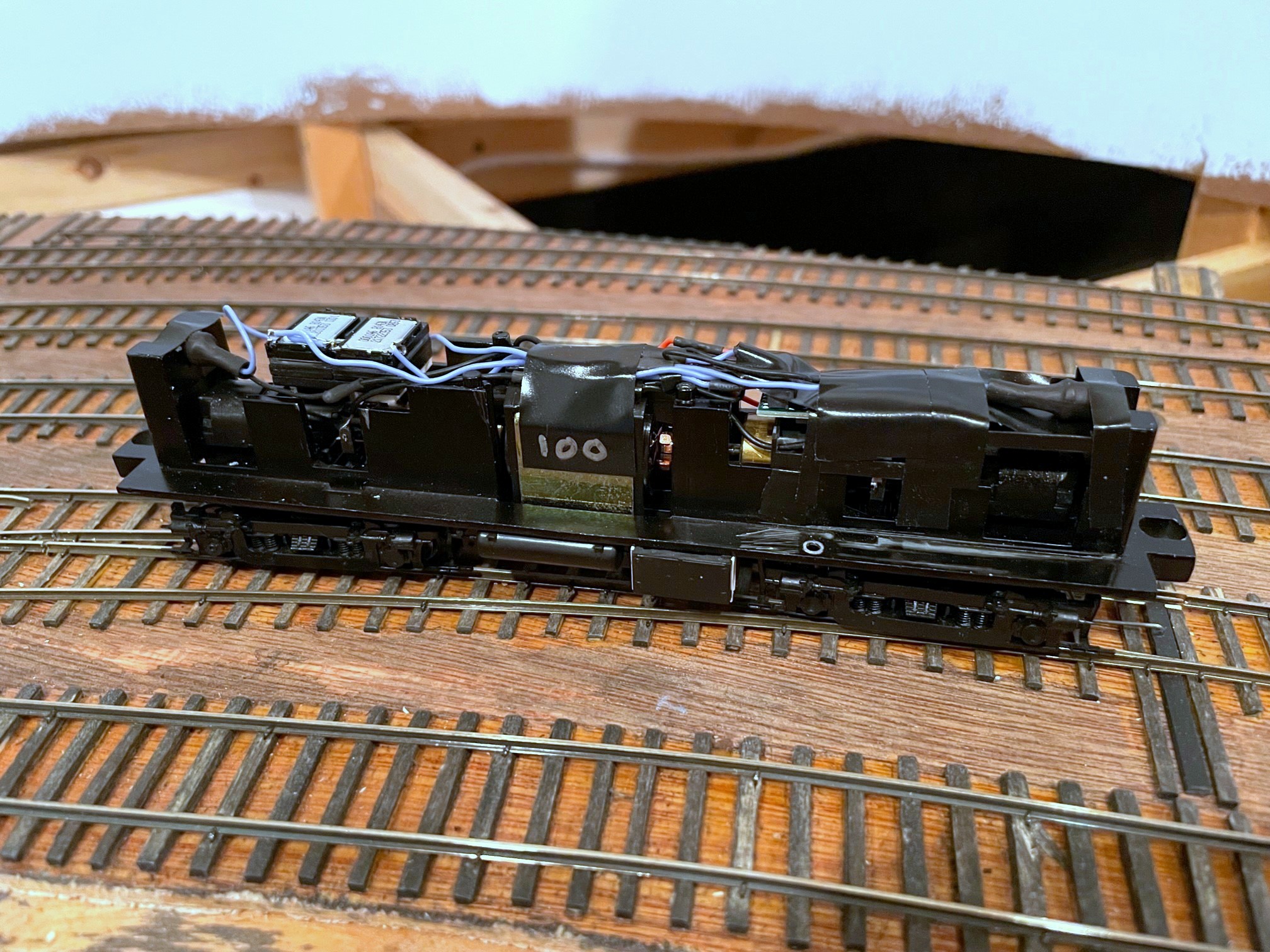
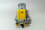
The tight quarters inside an Athearn RS3–the decoder is under the cab to the right side
Perhaps the most challenging detail modification was the end railings. The factory railings have MU stands that were easy enough to trim off, but the L&N used squared-off outer railing supports instead of the angled versions on the factory model. Engineering plastic is notorious tough to work with, so I hemmed and hawed over just leaving the factory angle before deciding that the squared look was distinct enough to warrant the effort. I started by using the corner of a file to notch out the 135-degree angle I would need to bend to 90 degrees to make it more pliable. Next, I cut the lower attachment spot of the angled support and cut the angled piece slightly shorter so it would bend to 90 degrees without overlapping the stanchion. Next, I roughed up the side of the stanchion so it would better take CA and glue (it doesn’t really “take” glue well even with roughing, but it does still better than leaving it slick). Finally, I cut a small piece of styrene to wedge alongside the stanchion and hold the angled piece at 90 degrees and secured everything as best I could with CA and liquid model cement.
On the inside, the toughest thing was adding sound. There is hardly any room at all inside the shell, so I had to make several compromises. I chose a 21-pin Soundtraxx Econami decoder because it’s very small, and the Alco 244 sound it produces is pretty decent. There is only one ideal open spot inside the shell, so I decided to use it for the speakers, a pair of LokSound 11x15mm “sugar cubes” wired in series with the small LokSound baffles installed. This meant the decoder needed to go in the cab section. This required me to cut away the center section of the body within the cab to allow the decoder to sit on top of the truck assembly and extend into both the long- and short-ends of the hood. This is not a 21-pin model, so I made a custom 21-pin harness by soldering short bits of wire that fits snugly into the decoder holes onto the locomotive wires.
Finished L&N RS3 108 from the right side
Once all the details were in place except the handrails, I touched everything up with black paint on 108 and gray paint I mixed to match 100. For 108, I was weathering to pictures of 108 on the CV Local in 1964 (see Ron Flanary photo here)–the fading on the roof is apparent, but the paint is otherwise fairly intact. I weathered 100 to pictures of it at DeCoursey Yard in Cincinnati in 1972 (see Brian Woodruff photo here), and it’s filthy! The first thing I noticed was 100’s factory paint was too dark. To “fade” it, I used a lighter gray and airbrushed it to lighten it up significantly. I wish I’d taken a picture of this step so you could see how much lighter it was–the weathering darkened it back up again, so I’m really glad I lightened it beforehand! I also sprayed a little dark gray onto the top of 108 to simulate fading, and I sprayed a little dark rust color onto both roofs and in front of the stacks and drybrushed some streaks under the battery boxes. Next, I gave them both a good black wash to grubby them up a bit. 100 also got some “oil stains” along the bottom of the carbody and in some of the hood door louvers. I’m happy with the lower oil stains but not the louvers–in retrospect I should have continued more layers of wash rather than using a thicker (but still watered down) black as it didn’t wipe off cleanly… my story is someone tried to wipe off the oil, and it just smeared… This model’s weathering is actually “backed off” a little from prototype photos to represent ~1968-70, believe it or not!
L&N RS3 100 left rearL&N RS3 100 showing cab details including engineer and canvas sunshade
After the washes and oil stains, I put the handrails on and added liberal sprays of tan and flat black to weather the pilots, trucks and fuel tanks. I also used tan lightly on the lower sides and top, and I used flat black liberally around the exhaust stack and lightly on the rest of the roof. At this point, all that was left was to reinstall the windows, add wipers, and paint and insert the engineers (two bicyclists from a Preiser kit) which required amputation of the left legs to get them between the cab sides and body sides. They add a lot of interest, and as these units always operated solo on the CV Local, it made sense to add them. The final details were headlights made from bits of fiber optic cable with the end melted into a lens shape and some cab wind deflectors, simple bits of leftover clear styrene packaging cut to size and painted on the back and edges.
So now between these RS3s and C420 1317, I’ve got sufficient L&N power to run the CV Local from about 1962-1977. I still plan on modeling a couple of PhIII RS3s at some point, to include one in boring spartan black (sigh…), but at least the L&N crew on the layout will have some nice-and-dirty locomotives to go with the gurgly and lumbering burble of the Alco 244 prime mover as they shift hoppers around the coal fields of southwestern Virginia!
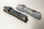
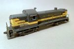
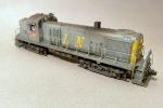
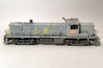
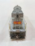
L&N RS3s 108 and 100 illustrating how much more the gray scheme shows weathering than the black
L&N RS3s 108 and 100, highly modified Athearn RS3s in original black and cream and early gray and yellow paint shcemes
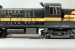
Finished L&N RS3 108 from the right front
Finished L&N RS3 108 from the right rear
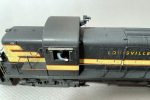
Finished L&N RS3 108 showing cab details including canvas sunshades and engineer
Finished L&N RS3 108 showing underbody details including the scratchbuilt equipment box along the tank and the scratchbuilt speed recorder
Finished L&N RS3 108 from the left rear
Finished L&N RS3 108 from the left front
Finished L&N RS3 108 from the left side
Finished L&N RS3 108 from the right side
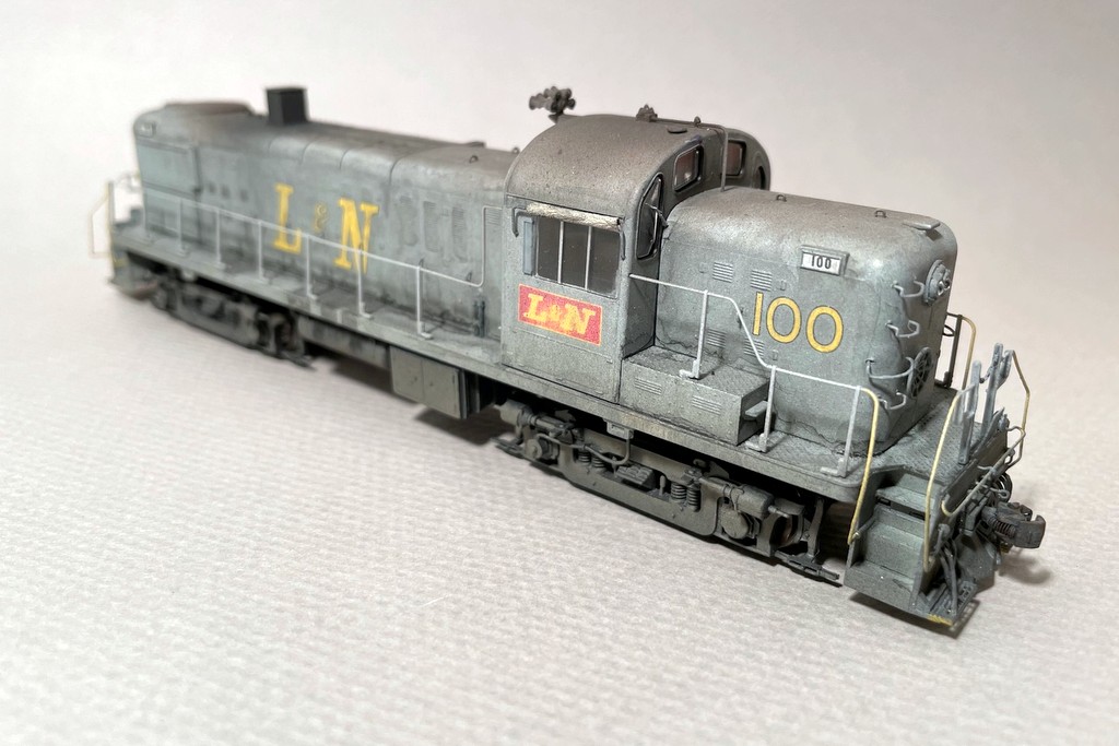
L&N RS3 100 right front
L&N RS3 100 left rear
L&N RS3 100 showing cab weathering
L&N RS3 100 showing finished pilot details
L&N RS3 100 showing cab details including engineer and canvas sunshade
L&N RS3 100 right side showing heavy weathering and oil stains
L&N RS3 100 left side
In-progress shot of L&N 100 showing grab irons and long-hood latches
In-progress shot of L&N 100 showing some of the pilot and cab details
In-progress shot of L&N 100 showing pilot details including copper-wire MU hoses and scratchbuilt pilot steps
In-progress shot of L&N 100 showing cab and antenna details
In-progress shot of L&N 100 showing scratchbuilt piping
Step 1 of canvas sunshades is to bend the rod and attach a piece of tissue paper
Step 2 of making canvas sunshades is to roll the tissue paper tightly and seal it with CA
The tight quarters inside an Athearn RS3–the decoder is under the cab to the right side
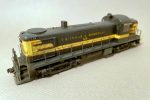
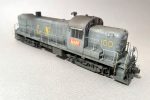
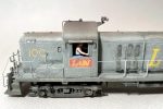
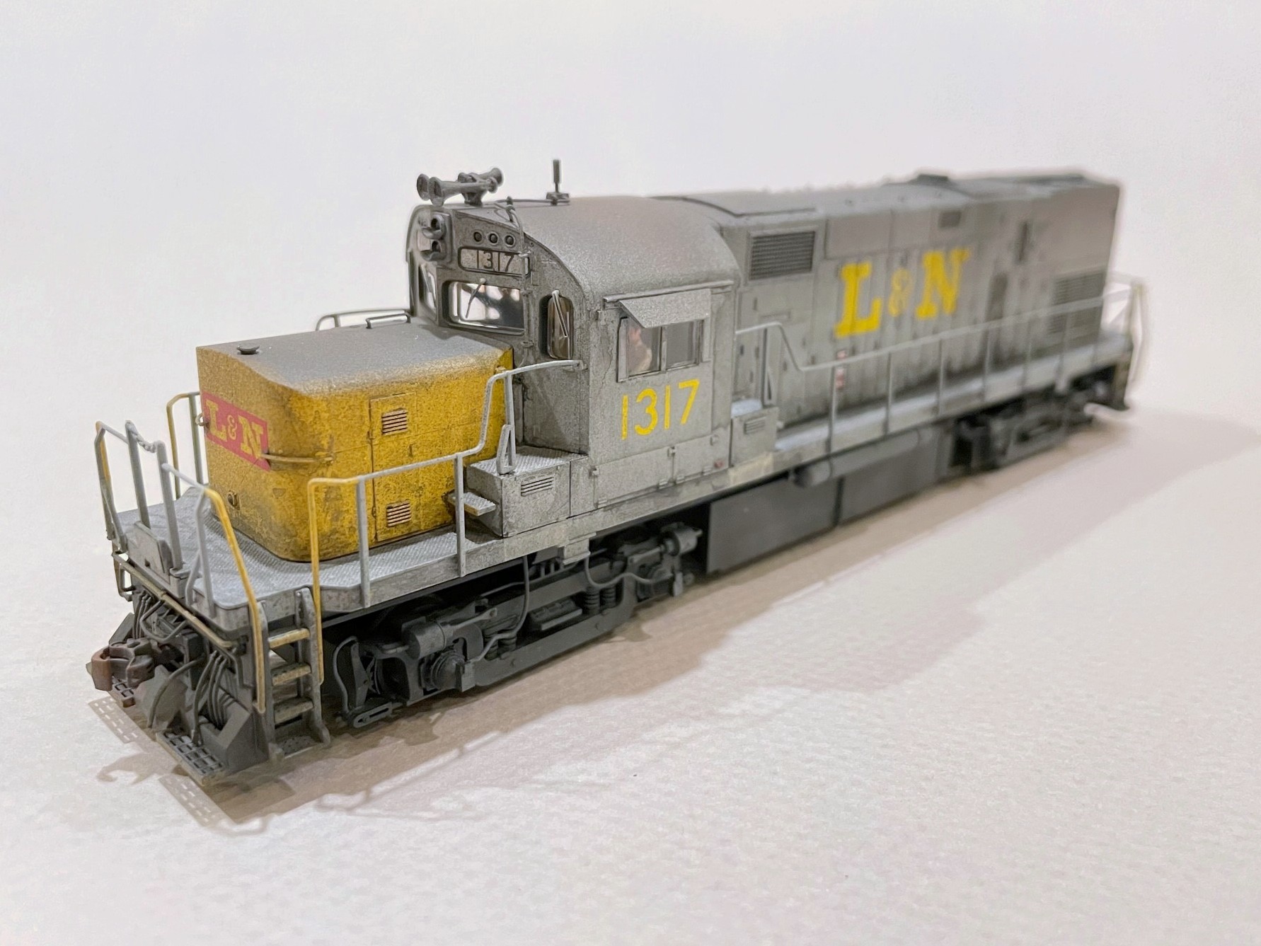
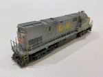
The Louisville and Nashville served the end of the Southern’s St Charles Branch via trackage rights, and the train that did the honors in diesel years was known as the Cumberland Valley Local or “CV Local” for short. This train, which also served the mines near Middlesboro, Kentucky, was usually meager in terms of tonnage, and a single locomotive was sufficient for the task. For my eras, the CV Local was usually handled by a single Alco RS3, and after 1974, a single Alco C420. Due to weight restrictions on the “Old CV” where this train roamed, the favorite C420s were 1316 and 1317, two ex-Tennessee Central units that happened to be the lightest C420s on the railroad. Needless to say, modeling one of these units has been on my list since I started building the St Charles Branch. So, meet ex-TC C420 1317 in HO scale!
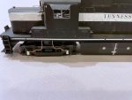
LN C420 1317 pre-paint wheel slip sensors
This model started as an Atlas Phase 2b C420 in factory-applied TC paint (why not?). While the Atlas details are pretty good out-of-the-box, there were a few things the model needed to be an accurate representation on this particular unit. Most noticeably, the TC units had very narrow, rectangular fuel tanks (part of what made them so light). I simulated this by removing the rounded sections of the Atlas fuel tank, separating the air reservoirs (I’d need them later), and patching the holes. The tank is still about 18″ too wide, but it gives the impression created by the narrow tank and makes this C420 stand out in a line of round-tank Alcos. The drain pipe on the left side is just a piece of Cat 5 ethernet cable with the insulation intact and a few bits of styrene for the bracket.
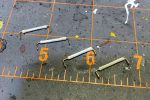
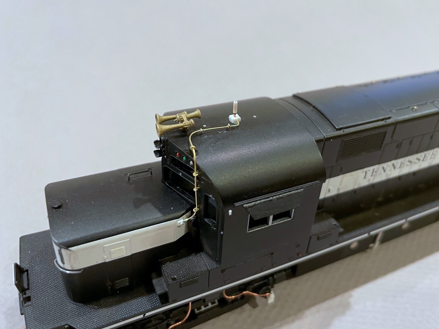
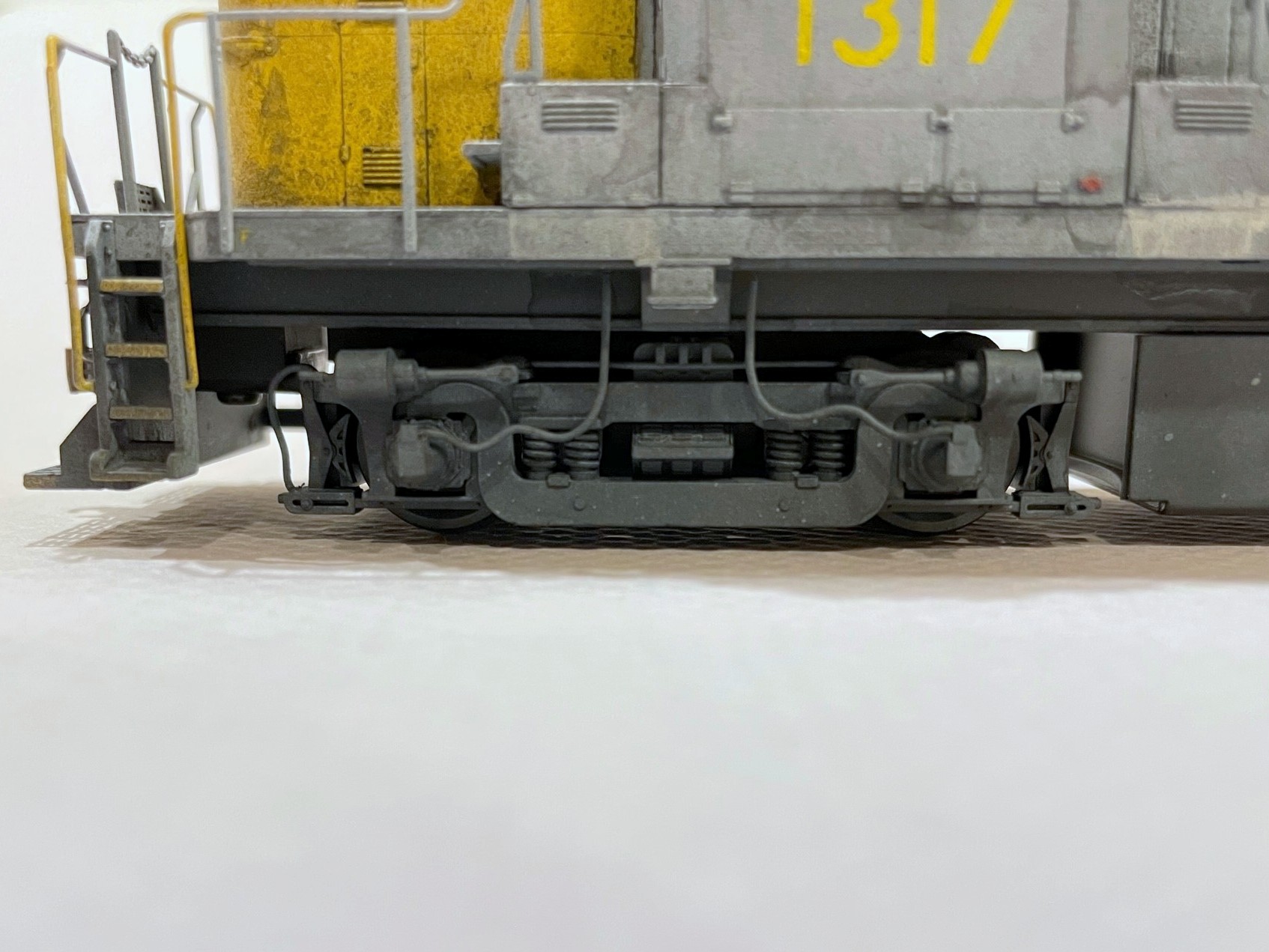
A few of the details are commercially available detail parts including a DW brass horn and DW air filter (added just before weathering where the bell was previously). Most, however, are homemade from bits of styrene, brass wire, and one of my favorite modeling materials, copper wire from old Cat 5 ethernet cables. The most challenging details were the wheel slip sensors that go over the four truck journal boxes on the left side of the locomotive. For mine, I used bits of sprue filed into a conical shape for the base. Next, I drilled a hole through the center big enough for the copper wire (stripped of insulation). I bent the copper wire so it extends through the truck sideframe to help prevent the assembly from being broken off. From there, the wire bends up and then toward the middle of the sideframe where I bent it into a sagging shape per photos. Next I used bits of styrene to frame the wire on top of the conical housing and then to cap the frame to simulate the portion where the wire comes into the housing. Similarly, I bent bits of copper wire into the shape of sand lines for the pilot end of each sideframe (there’s not enough room on the fuel-tank end).
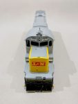
LN C420 1317 pre-paint cab details
The next most challenging detail was the antenna conduit. Photos are clear that the L&N added a long antenna conduit from the nose to the roof along the cab face. I couldn’t find any roof shots of 1317, so I inferred the rest from other units: 1) conduits are usually paired with a box under the antenna on the L&N, and 2) firecracker antennas in the center of the cab roof are the most common. The conduit was carefully bent from .012″ brass wire and held in place by eye bolts (these happen to be homemade as well from .010″ wire). The base is a cube of styrene, and the firecracker antenna is just a piece of copper ethernet wire with the insulation partially removed (thanks to my friend Stuart Thayer for teaching me this trick). Rounding out the initial cab details are some sunshades out of the spare parts box and a couple of headlight deflectors made from bits cut from the “ears” of a Kadee coupler box.
The roof of the model has molded-on lift rings, and I decided to shave these off and replace them with wire. I used .010″ wire bent around a thumbtack to create candy-cane shaped lift rings–only the long end is actually inserted into a hole, the other side is just pressed into the body a bit. For the pilots, I reused most of the Atlas factory parts including the MU cables, coupler cut bar and long grab. I also used the factory drop steps but added a piece of thin styrene to make it solid instead of a grate per prototype photos. The train line hose, like my freight car hoses, is – you guessed it – a piece of copper ethernet wire bent into shape and crimped at the end to form the glad hand. Finally, just before painting, I noticed that the L&N had removed the hand brake from the front of the cab, so I did the same, replacing it with a square-shaped length of styrene and a hole.
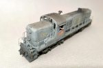
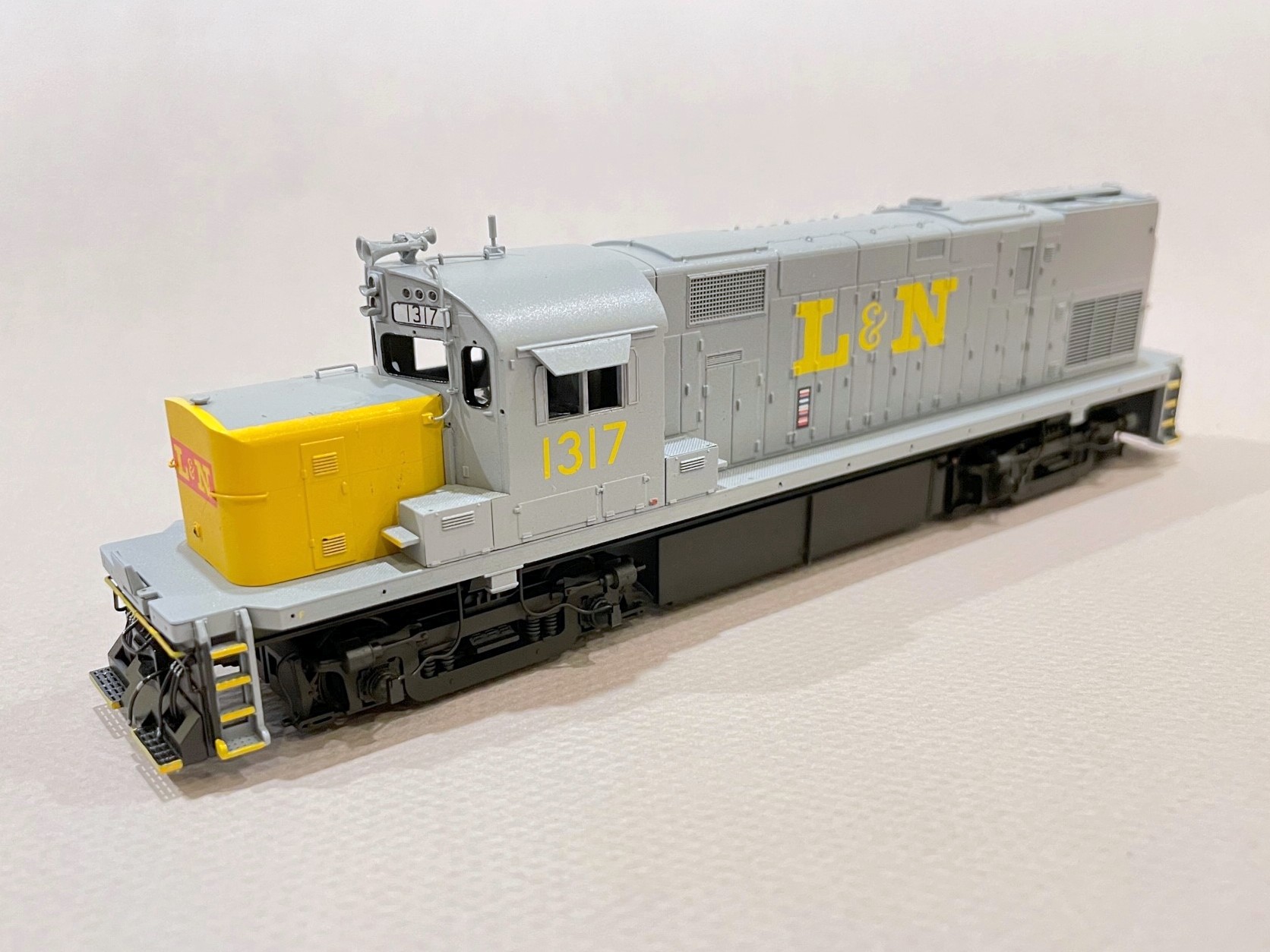
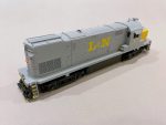
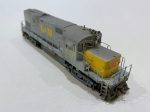
LN C420 1317 painted left front
Before painting, I sanded the TC paint lightly to remove some of the sheen and “3D” nature of the striping, but I left a little of the raised paint so at certain angles you’d be able to still see the faint lines of the TC paint (again, why not?). I still have a lot of Testors Model Master acrylics, so after examining photos, I decided on “light ghost gray” for my base color and “insignia yellow” for the nose. I primed the whole locomotive with black and then masked the pilots before airbrushing the gray. The nose was easy because it’s a separate piece, so all I had to do was spray it gray, mask the rectangle for the top, and spray the yellow. I used a combination of a black sharpie and brushed black paint for the window and number-board gaskets, and a little blue and red paint for MU covers, fuel fillers, and a couple other things on the gray that look red in photos. Marker and walkway lights are just semi-gloss black paint. The final step was spraying the painted shell with Rustoleum clear “high luster” lacquer to protect the paint and make a better surface for decals.
I used the Microscale set 87-823 “L&N Locomotives Gray & Yellow 1970-80” for most of the decals, using dozens of liberal coats of Micro-Sol and Micro-Set and a damp paper towel to help the decals settle in. The numbers on the number boards are from a Microscale SCL diesel set–they’re a little smaller and look better on Alco boards. One detail I added during this step was the cab wind deflectors flanking the side windows. These are just bits of clear styrene from an Intermountain wheel box. I cut a strip the width of the deflectors, masked a strip down the middle, painted the back the gray color of the body, and used a silver Sharpie marker on the sides and around the masking. After removing the masking tape, I cut the deflectors to length, added a little dog-ear, and used the silver Sharpie to hit the cut ends. A dab of CA on the cab secures them in place. This method models an otherwise delicate detail in a manner that’s resilient to routine handling on the layout.
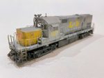
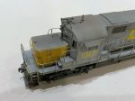
LN C420 1317 finished wheel slip sensors
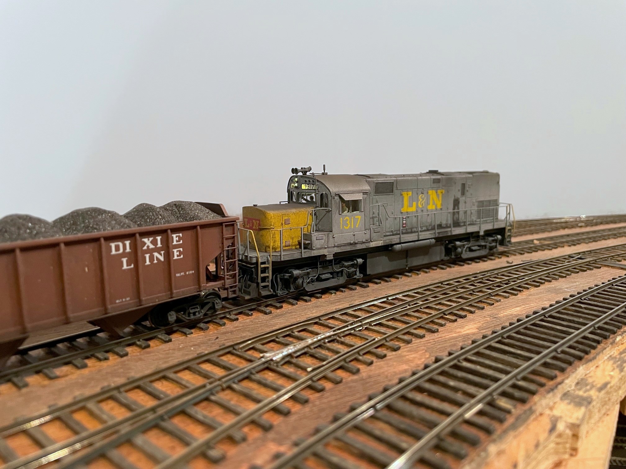
Weathering on this unit, as you can see, is substantial–these units worked the coal fields, and baths are few and far between. Besides, part of an Alco’s charm is it’s ability to spew oil and black smoke everywhere. Working from photos, I started with the oil seeps on the engine doors–these are mostly around the bottom, but in two photos from 1974, an entire door on 1317’s left side was covered in oil, so I modeled this. I used watered down flat black paint, alternately dabbing paint and water to get the consistency right and wiping in a vertical direction between coats. Next came several black washes of water with some black paint mixed in. I brush it on in a section, wait 30-60 seconds, then wipe in a vertical direction to simulate grime streaked by rain. The trick is to do multiple light coats until you’re happy. A little drybrushed sand color under the battery boxes finished the preliminary weathering.
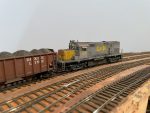
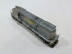
LN C420 1317 working Mayflower on the CV Local
I left the handrails off until I was ready to airbrush. Airbrushing consisted first of some tan sprayed heavily on the pilots, trucks and fuel tanks (with the air reservoirs now mounted). Next came flat black primarily on the roof–moderate in most areas and thick around the exhaust stack. Finally, I used a little rust on the pilots and roof to give it just a bit of a rusty brown look. All that remained at this point was to reassemble everything, including the cab glass that had been removed earlier, and add a set of A-Line windshield wipers painted silver.
Overall, I’m very happy with how 1317 turned out, though I think I overshot the weathering a little. The unit was repainted in 1974, and I was shooting for weathering circa 1976. I think I nailed the weathering circa 1978, but it’s still a pretty realistic representation of how filthy these Alcos got in the L&N’s coal fields during the coal boom. This is also the first Alco I’ve ever finished, so I also enjoyed the challenge of making so many details from scratch. The unit came with factory sound by Loksound which does a great job of replicating the lumbering burble of the Alco 251 prime mover, so she’s a blast to operate! I’m just happy the CV Local finally has a finished L&N unit to head it up which should make the next ops session more fun.
You may remember Southern GP7 2187, a Proto GP7 I finished last summer. Well in addition to fixing the railings and steps for my 1970 timeframe (black and white instead of yellow), I decided to install sound. Now sound is something pretty new and intimidating to me, but after running a couple factory-equipped sound locomotives, it was tough to go back to no sound. I finally decided to just jump in! There are many great sound decoders out there, and everyone has their preference. I won’t claim to be an expert, but after doing some research, I decided to start with some Soundtraxx Econami decoders. As you might guess from the name, these are “budget” decoders that run about 2/3 the cost of a full-featured sound decoder from any manufacturer. The Econami is pretty basic, but it does have the key features I need, and it uses the same basic sounds as the more expensive Tsunami 2s. Best of all, the Econami Diesel version allows the user to select from a handful of prime movers including everything I need for my first-generation fleet: the Alco 244 for RS3s and the non-turbo EMD 567 for Fs, GP7s and GP9s.
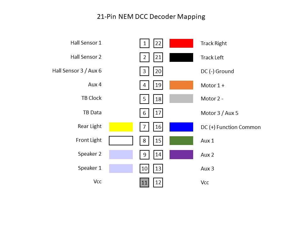
Basic mapping of a 21-pin connector for DCC (use at your own risk)
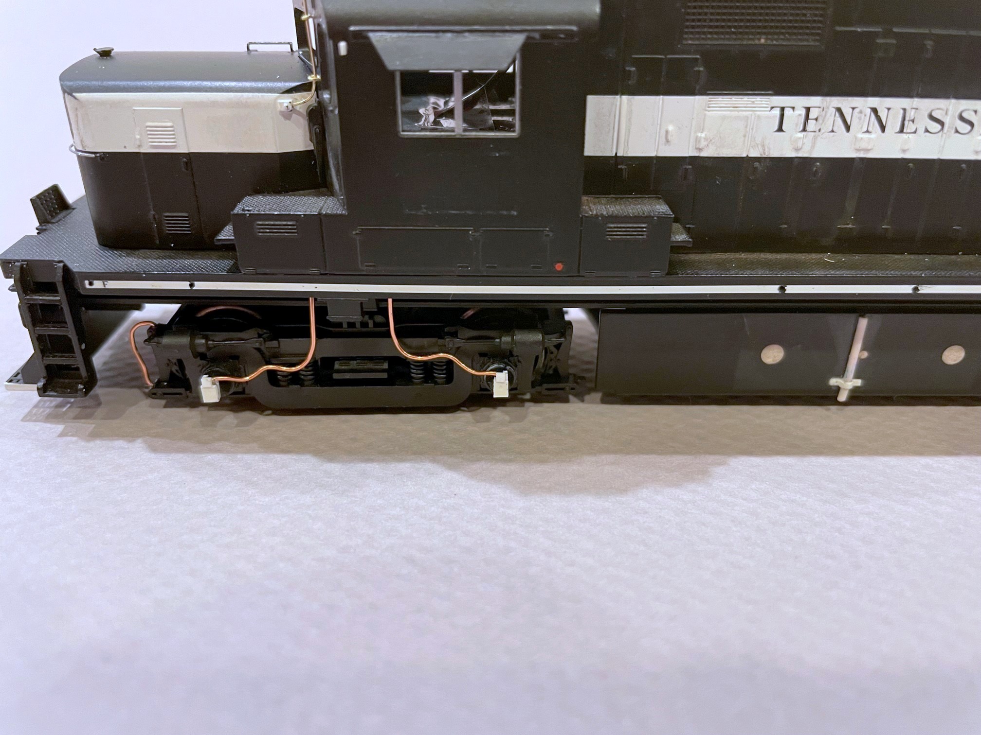
Soundtraxx makes two versions of the diesel Econami, the larger ECO-PNP and the smaller 21-pin ECO-21PNEM. I picked up a couple ECO-PNPs, one of which was intended for 2187, but once I got the decoder, it was obvious that it wouldn’t fit without major modification to the large metal weight–I needed something smaller. After installing the PNPs in an RS3 (just barely) and an F3A, I decided I was happy with the sound produced by the Econami and a pair of mini cube speakers, so I looked to see if I could install the smaller 21-pin decoder in the GP7. The 21-pin arrangement is newer, and I was surprised at how tough it was to find a cheap 21 pin harness I could wire into the locomotive. You can find cheaper ones in Britain, but it was going to cost me an extra $20 to get one in the states–what’s the point of using the Econami if a simple harness was going to eat up all the savings?
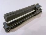
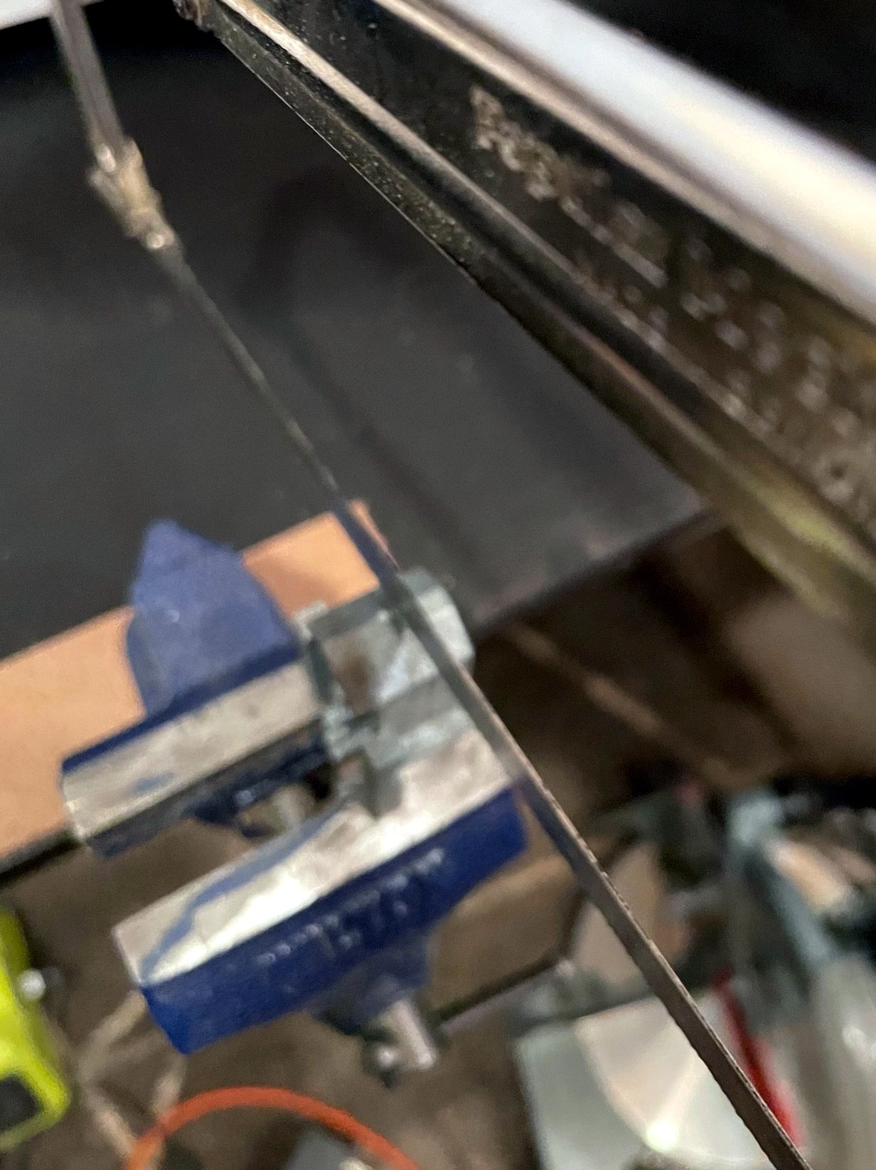
Taking 8mm off the height of the weight in the nose of the Proto GP7 to make room for speakers
So, could I get the 21-pin Econami to work without a harness? While it was a little tough to find info, I finally figured out the mapping of the 21 pins (thankfully German shares some commonality with English…). I knew it wouldn’t be practical to solder directly into the decoder (the pin holes are tiny and close together), but I thought I might be able to shape the wires to act as pins, so I ordered up an ECO-21PNEM. What I found was I could tin the wires on the locomotive, cut the end so about 2mm of metal was exposed, and then carefully insert the wire into the correct pin hole. While the connection is not bulletproof, it’s snug enough that the wires don’t come out easily, and if you can push the wire in until the insulation is flush with the board, there’s little chance of a short. For the extra wires (e.g., speaker wires), I used 30 AWG stranded wire tinned with solder–I had to use a little extra solder to get a snug fit, so a 28 AWG wire would probably work as well. Once I verified everything worked, I used a piece of electrical tape to hold the wires down and in-place.
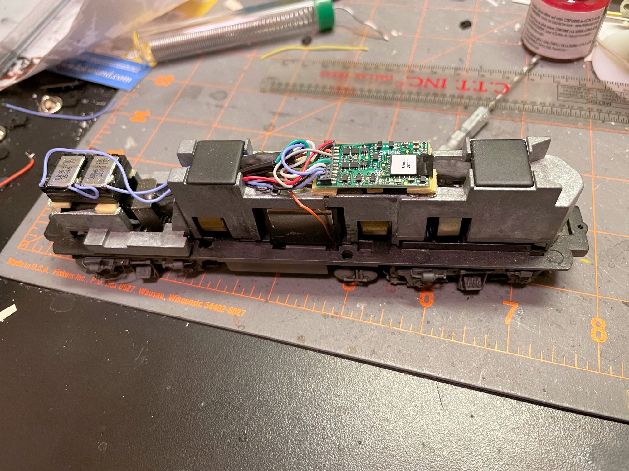
Using a 21-pin Econami decoder without a 21-pin harness
Now for the speaker. Unfortunately, I decided to use the large clear plastic blocks for the number boards and lights, so the little room that was left in the top of the shell was taken up. I decided the best course of action was to take the weight off and remove about 8mm of metal height from the nose section with a hacksaw. After filing the cut clean, I was ready to install the speakers. I’m using the 11 x 15mm cube speakers made by Loksound. You can find a lot of sources for speakers this size, but I love that the Loksound versions come with different baffle arrangements including both short and tall and a base to install two speakers side-by-side (my preference). I built a double baffle with the short walls using CA and connected the speakers in series (16 ohms impedence). Yes, the decoder is 8 ohms and the speakers are 16 ohms. My research leads me to believe this is not ideal but is acceptable as long as I don’t run the amp at max, which I don’t–if you have a good technical reason why this is not a good idea and will damage things in the long-run, please feel free to post a comment!
So, in the end, I was able to fit a sound decoder and two small speakers into the Proto GP7 with just a small, one-cut modification to the body weight, and I’m really happy with the sound! I’ve got a Soundtraxx Tsunami 2 EMD diesel decoder now as well, so I’ll do a comparison at some point and let you know how I think the Econami compares. For now, I’ll enjoy the chugging sounds of the EMD 567 and hauling coal hoppers interrupted occasionally by the chimes of a Nathan M5! St Charles is now a much louder place.
Today was a big day!… but it shouldn’t have been. It’s been an embarrassingly long time since I completed a locomotive model… like 7 years. Now it’s been less than a day as I put the finishing touches on Southern GP7 2187 today. This model started as a Proto 2000 GP7, and I’d gotten it through at least its initial detailing and coat of black paint several years ago. Last week, I finally decided it was time, and I decaled, added the last of the details, and weathered it.
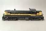
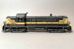
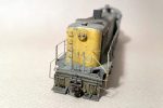
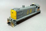
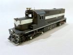
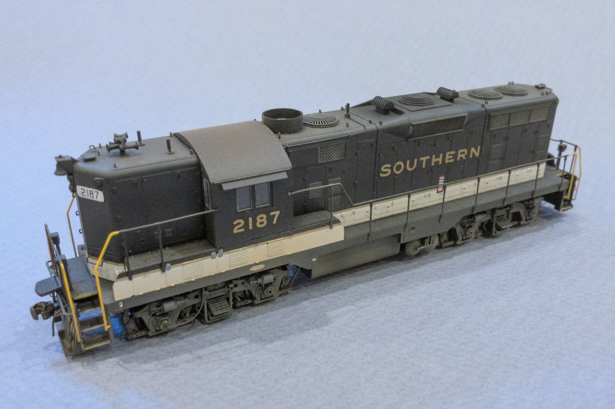
Southern GP7 2187 from a modified Proto 2000 model
I modeled 2187 as she appeared around 1970. This was one of a handful of GP7s the Southern modified with Locotrol in the 1960s (hence the white number boards), but it seemed to spend most of its life in secondary service. Photos place it in southwestern Virginia in the late ’60s and again in ’71 after a trip to the shop that added the Southern-style sunshades and ACI tag. Modifications to the model include a 36″ dynamic fan, fan shroud and blank grill cover, scratchbuilt spark arrestors, modified fuel tank skirting, Southern-style sunshades, 5-chime horn, and Locotrol details like the 3 antennas and extra conduit.
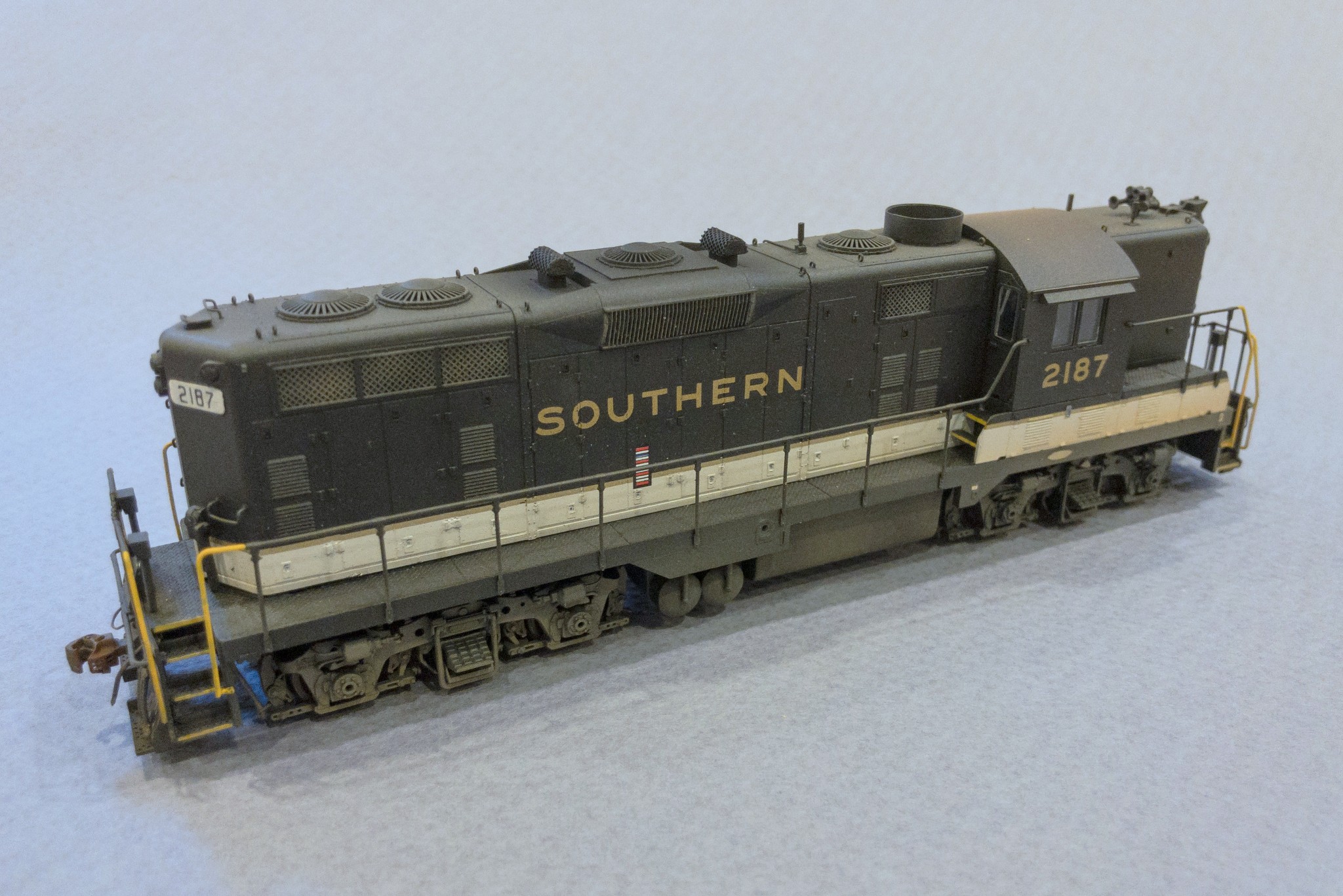
Southern GP7 2187 from a modified Proto 2000 model
Southern GP7 2187 from a modified Proto 2000 model