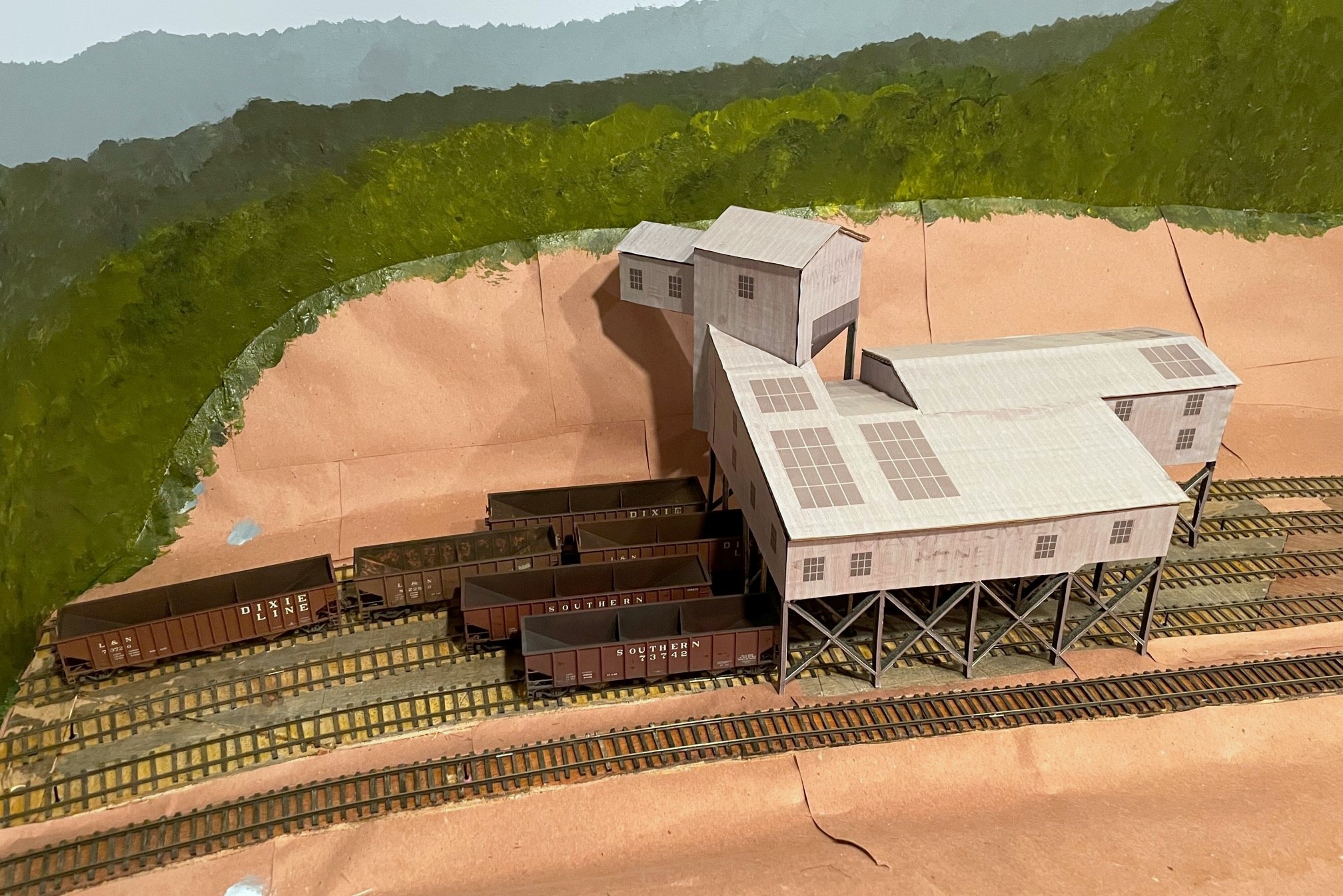
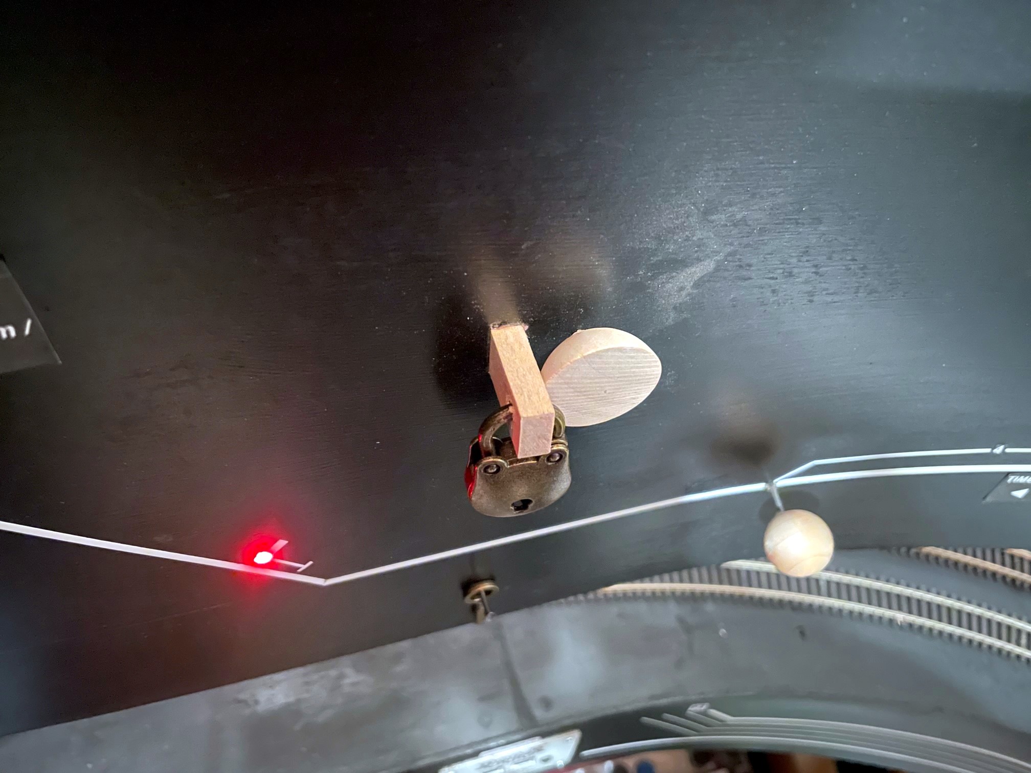
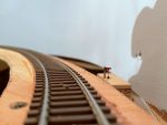
Handbrakes in action holding empties securely above the Mayflower tipple
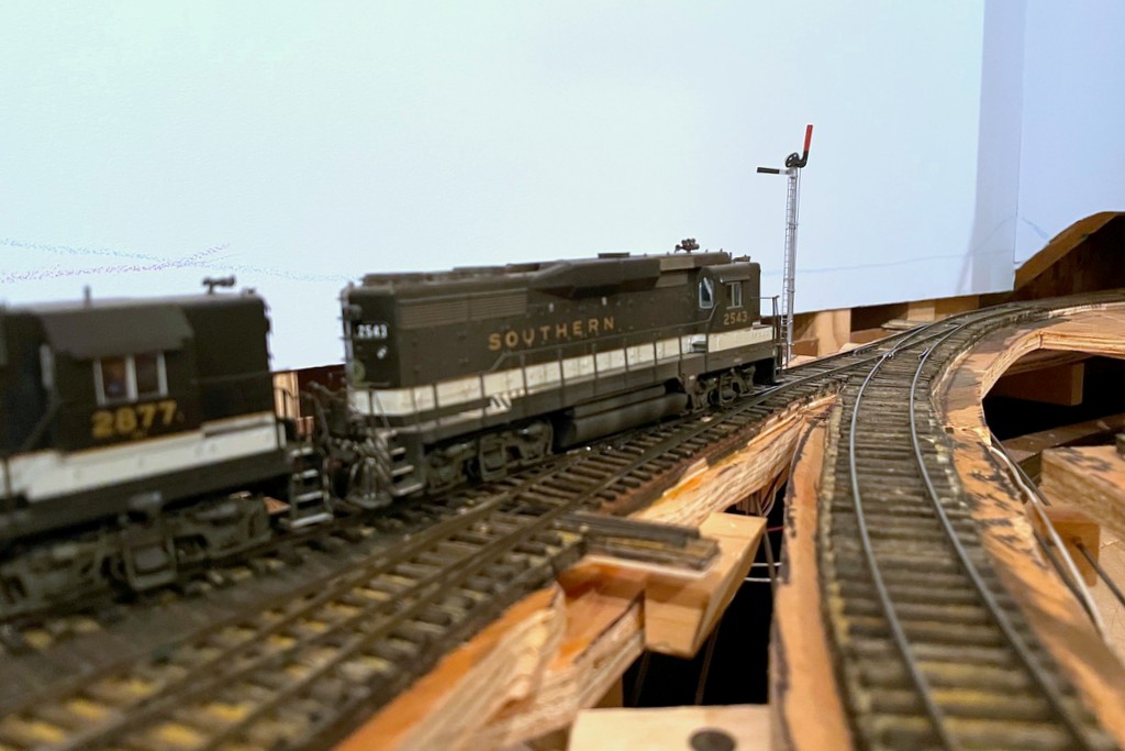
The ability to set handbrakes to keep cuts of cars in place on a grade is a crucial part of railroading, and a model railroad is no different, especially one set in the Appalachians. I’ve covered my technique for building manually deployable handbrakes via a retractable wire between the rails (article here), but the controllable brakes are complicated to make and install, so I reserve them for areas where I’ll be holding long cuts of cars on a steep grade or for where I need to hold a car for a while and then let it loose for some “gravity assisted switching.” But there are several dozen spots on the layout where I’ll need to spot small cuts of cars on slight grades, so for these areas, I wanted something simpler. I also like free-rolling cars, so tricks like putting a tiny spring on the end of one of the axles was also off the table–it needed to be something in the track. Enter the cheap plastic paintbrush! Each paintbrush handbrake costs just cents to make, and I can easily make and install a dozen in under an hour.
I picked up a box of 100 inexpensive plastic paintbrushes a couple years ago when the local Christian bookstore was having a big sale. I didn’t know how I would use them, so I put them away for a rainy day. That day came when I was playing around with different ideas for holding cars in place. It needed to be something I could roll cars and locomotives across easily without derailing or causing too much friction that would also be sturdy enough to hold a car when spotted over the brake. I first tried two methods that I’ve seen work for others. The first is a little dot of CA on top of the rail, but many of my spotting points were just too steep for this. Next I tried little lengths of fishing line mounted between the rails–these are good because they’re tough to see and work pretty well, but they make a noticeable “plink” every time they clear an axle or a hopper bay… in sections of the yard where I had several in a row, it sounded like a tiny music box playing a discordant tune!
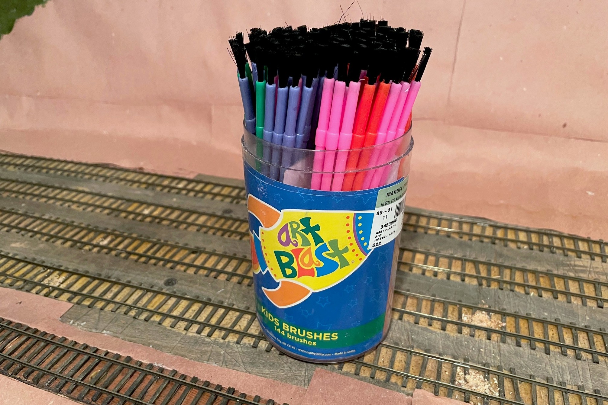
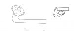
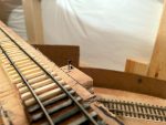
The starting point for handbrakes are inexpensive plastic paintbrushes from an art or hobby store
Then I remembered the brushes. The plastic bristles are pliable enough to give when trains are moved across them but stiff enough to hold a car when no other force is exerted. They could also be trimmed both in height and in density using a pair of scissors. They are certainly more noticeable than the fishing line or CA dots, but my hope is they’ll blend right into dirty coal-covered tracks, and those that don’t blend in can be painted to look like weeds. Even with nothing to disguise them, I find they don’t draw the eye much anyway.
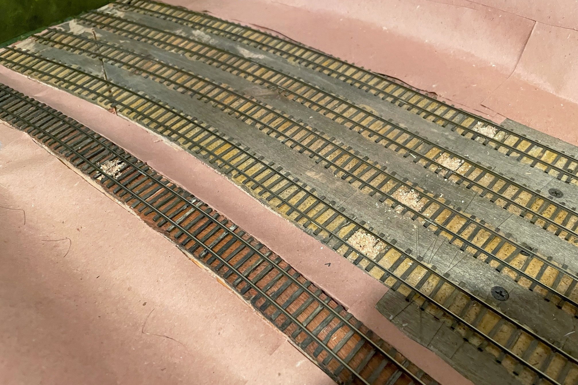
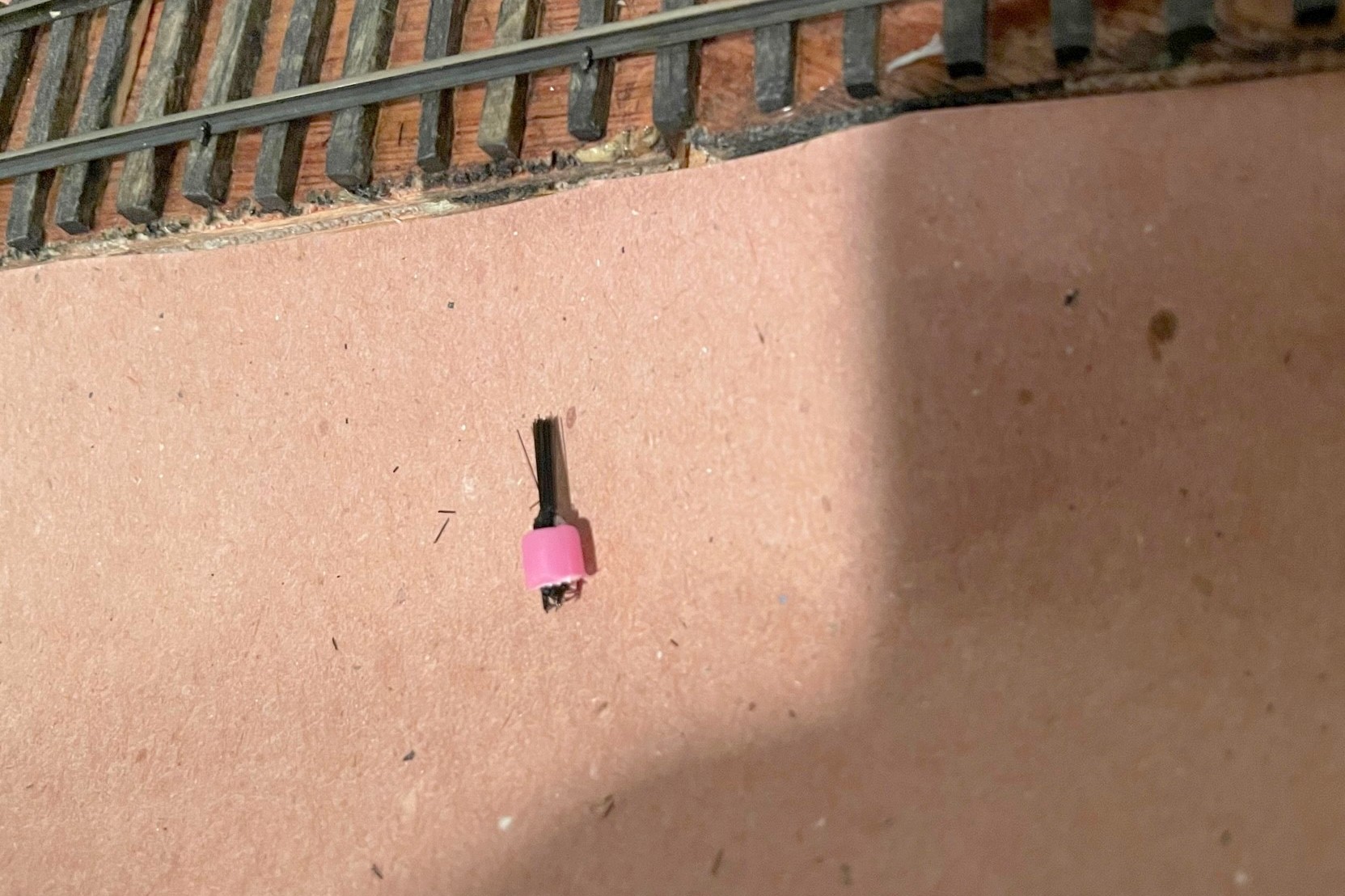
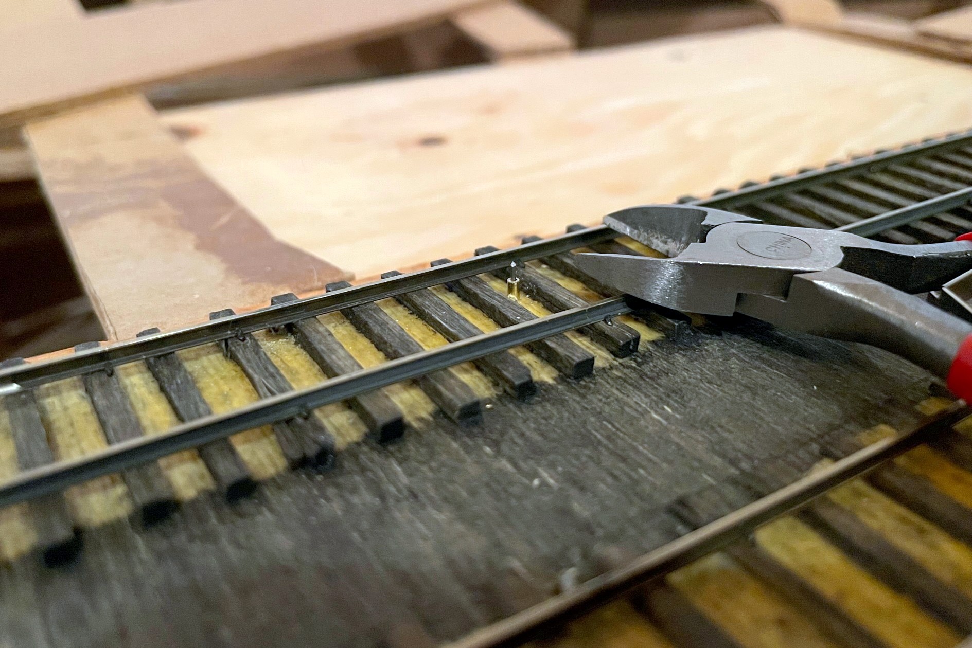
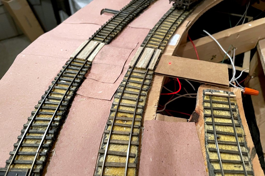
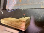
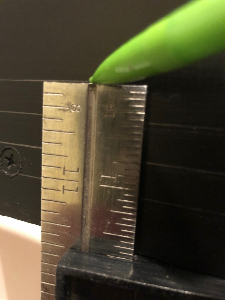
Step 1 is to locate where you need the brakes and drill a hole–the hole is offset to avoid wear-and-tear on air hoses
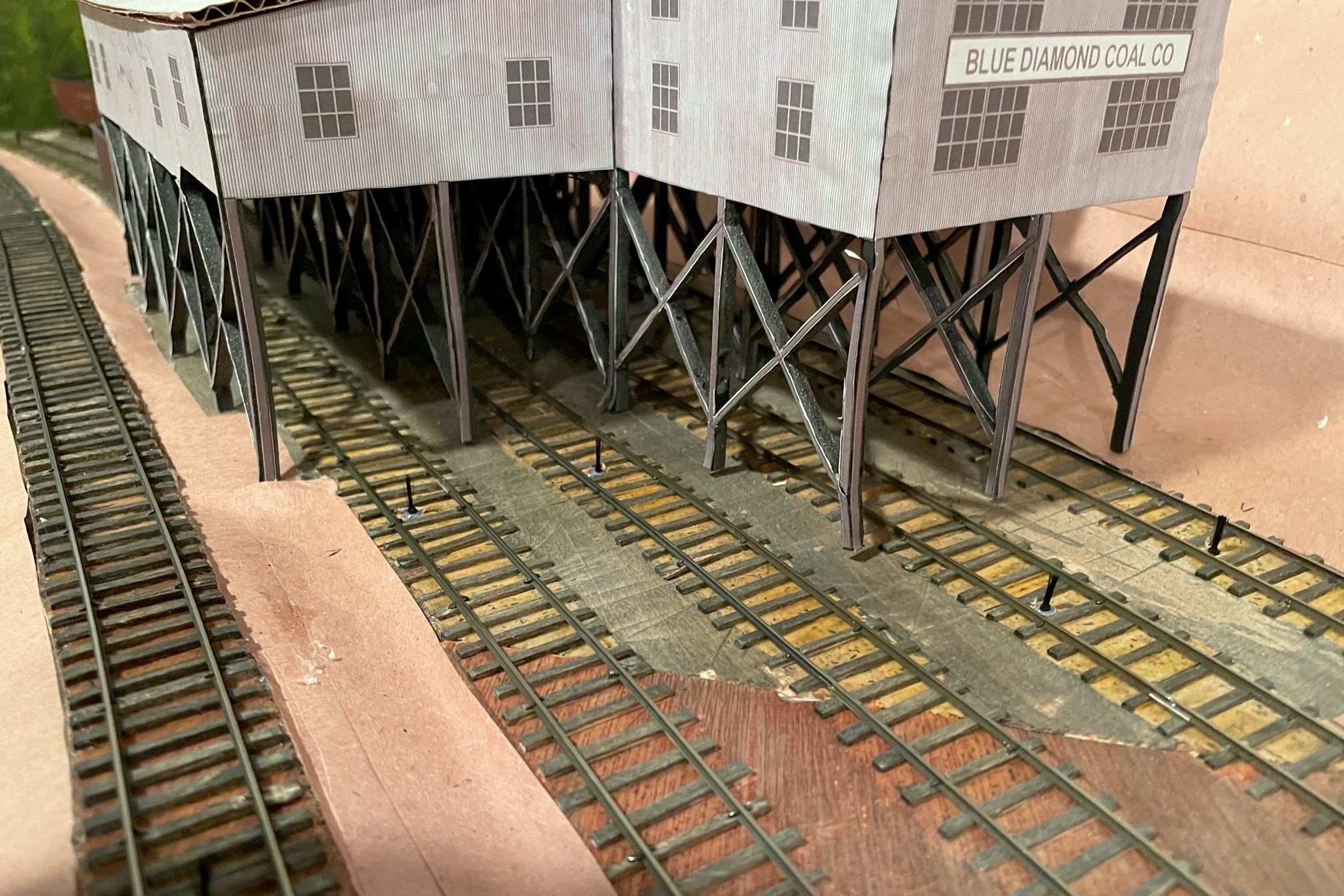
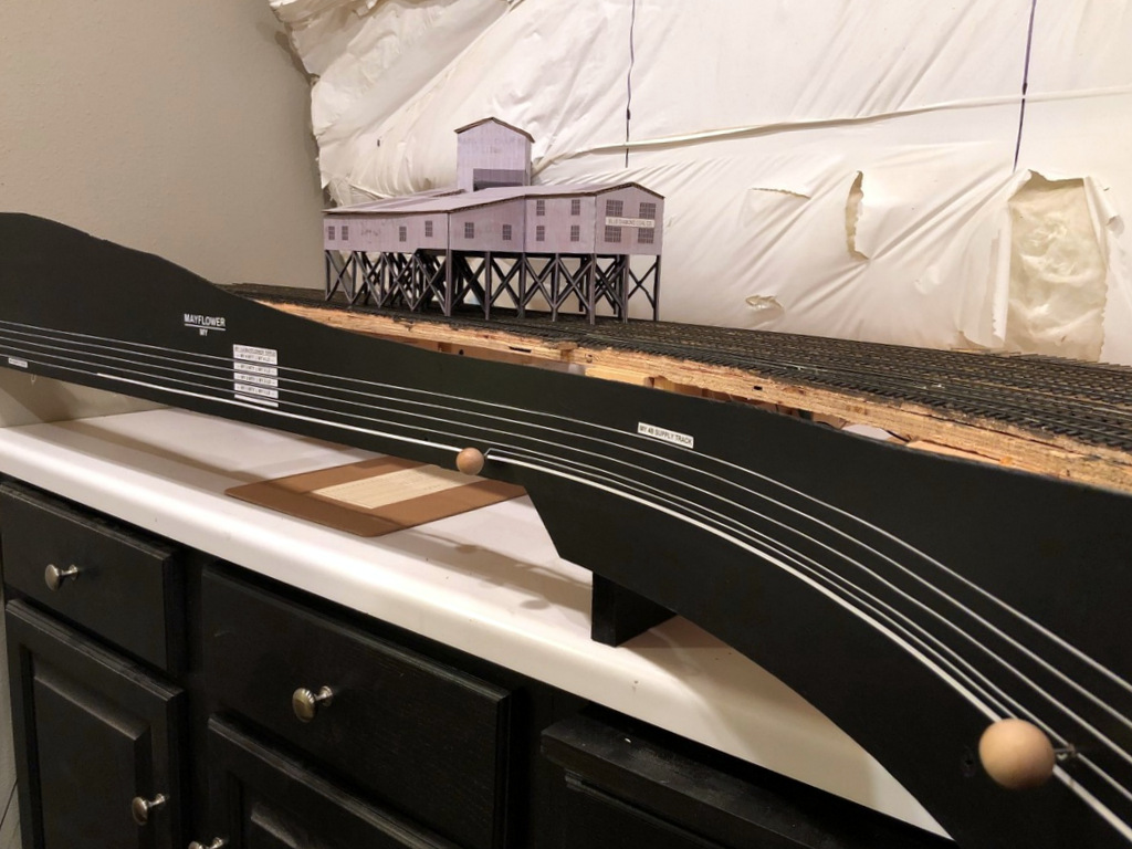
The first step is to locate where you want to install the “brake.” Figure out where you want the car or cut of cars to sit, then mark the spot where the most downgrade axle will sit–this is where you want the brake. In some cases, like the end of a track, you can mark the spot of the downgrade axle of the upper truck–I use this at the end of stub tracks where I need all the room I can get. For tipple tracks, I find it useful to have up to four handbrakes per track. One at the uphill end of the empty track to hold a full cut of empties, one just above the tipple to hold a shorter string of empties, one just below the tipple to hold a shorter string of loads, and one just before the fouling point of the downhill switch to hold a longer string of loads (or any “gotaways”).
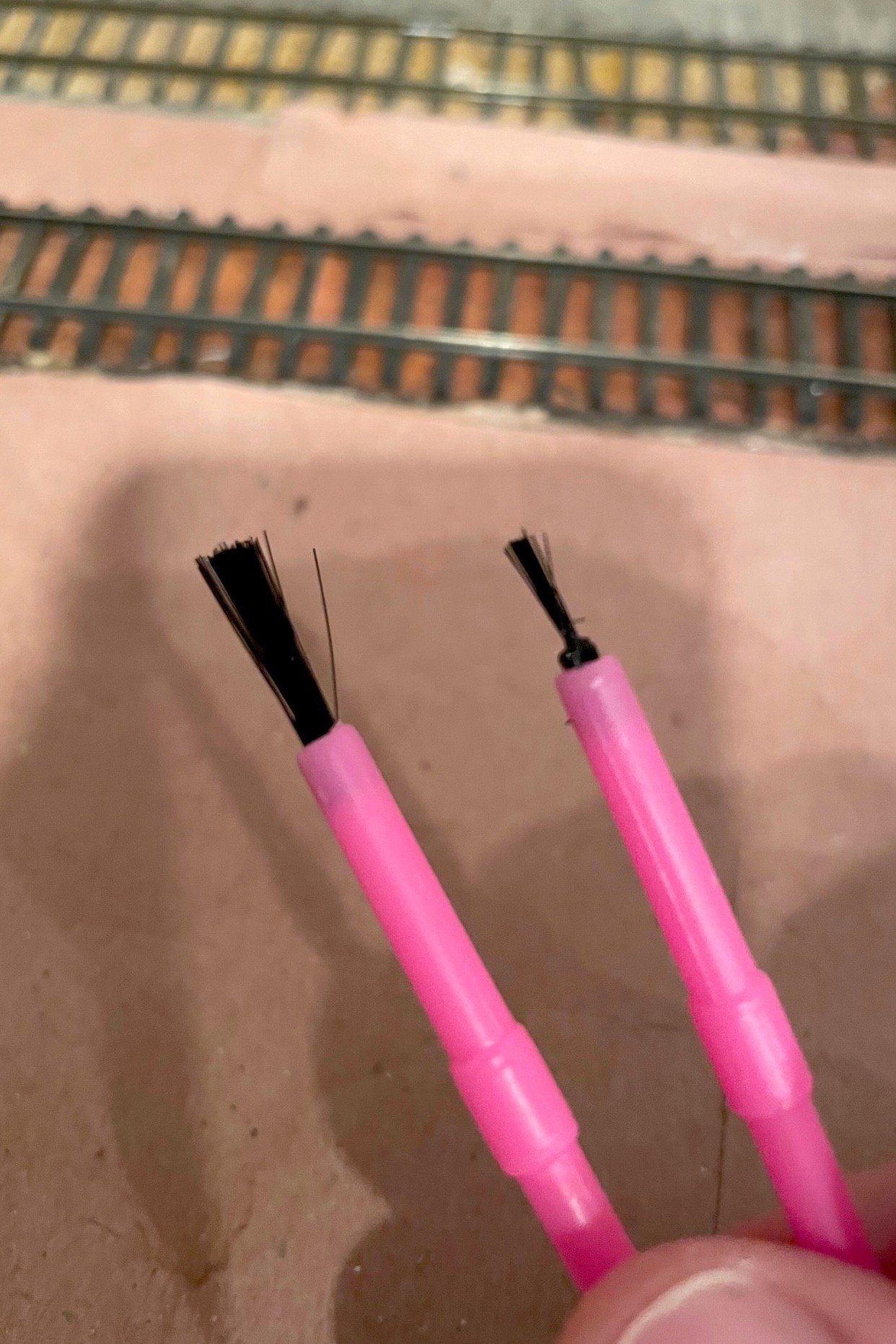
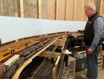
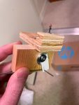
Starting and ending points with the brushes, just a little off the top and thinned down with scissorsThe finished “brake” ready to install between the rails
The second step is to drill a hole between the ties for each hand brake location. I found a 5/32″ bit drilled about 1/4″ deep worked for my paintbrushes, and I offset my holes closer to one rail to avoid constantly hitting delicate air hoses on cars. To prep the paintbrush, I first cut off about 3/16″ of the bristles with scissors–the idea is to have them tall enough to catch axles but not the sills of the cars or cut levers. Then I thin out the bristles by repeatedly cutting into the brush with just the tip of the scissors while rotating the brush around. How much you thin it out depends on the grade and how many cars you want to hold, but for my light grades, I trim down to about the last 20 or so bristles. It’s easy enough to thin them a bit more once they’re installed, and if you get it too thin, it’s easy to just make another. Then I use scissors and cut off the brush end of the paintbrush leaving about 3/16″ of the plastic handle to keep the bristles secure. Installing them is usually a press fit, but if they’re loose, a little carpenter’s glue will help hold them in place. I press them down until the handle is below the ties where its bright color will be covered up by ballast.
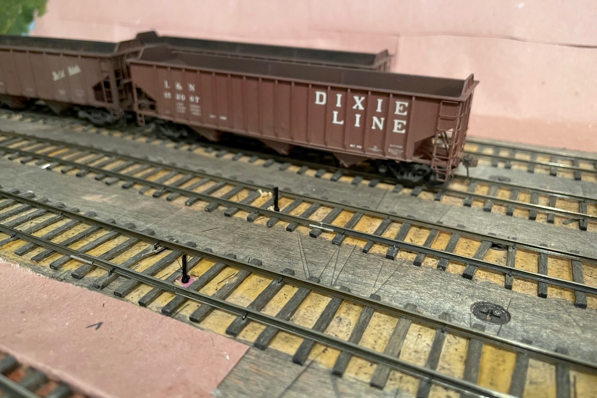
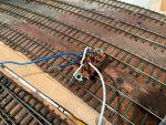
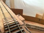
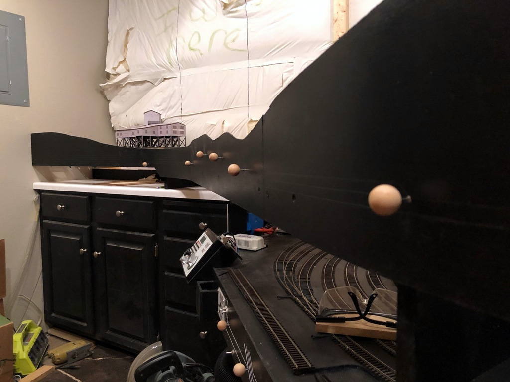
Paint brush handbrakes installed between the rails
The final step is to test the brake by running strings of cars across them to make sure they don’t derail and don’t cause any noticeable jerking movements in the cars (if you look closely, you’ll see some movement, you just want to avoid it being distracting). When you let go, the cars should roll and then come to a gentle stop once they hit the brake. Also test a locomotive across each brake to make sure it doesn’t interfere with the trucks (this is the most stressing pressure on the brake). On steeper grades, you may find having a few brakes in series is needed to stop a string of rolling cars, or you may have to spot the cars exactly on the brake to prevent them from rolling in the first place. It’s easy enough to add and remove these brakes while you’re trying to figure things out. In the end, I’ve found this is a great way to hold cars in place without the worry of damaging cars or scenery, and it’s tough to beat the price and ease of installation!
Finished “handbrakes” to hold the loaded cars in front of the Mayflower tipple mock-up
The starting point for handbrakes are inexpensive plastic paintbrushes from an art or hobby store
Step 1 is to locate where you need the brakes and drill a hole–the hole is offset to avoid wear-and-tear on air hoses
Starting and ending points with the brushes, just a little off the top and thinned down with scissors
The finished “brake” ready to install between the rails
Paint brush handbrakes installed between the rails
Finished “handbrakes” to hold the loaded cars in front of the Mayflower tipple mock-up
Handbrakes in action holding empties securely above the Mayflower tipple
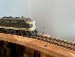
The St Charles Switcher crew sets the handbrakes to leave a string of loaded hoppers on the grade while working the yard
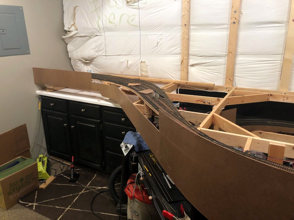
Gravity is a major factor in prototype railroading, but it can be quite troublesome for a model railroad. Very little real track is actually completely flat, so train crews routinely use the handbrakes on individual cars to hold them in place in yards or sidings. Not only do handbrakes hold cars in place, but in the Appalachians where I model, gravity and handbrakes were often used to move cars from empty tracks to tipple loading points, to move loads into the right track below the tipple, or even to run-around a caboose at the end of the line. Modeling working handbrakes on individual cars isn’t very practical, so what is a model railroader to do? Some install springs on the ends of a car’s axles to use friction to hold the car, but this can’t be “turned off” to allow the car to roll freely. Others use little picks they stick into the ballast to hold cars in place, but this can be destructive to scenery, and it leaves an un-prototypical giant stick next to a cut of cars. I’ve adopted a method of fascia-controlled “handbrakes” on the tracks which works well for my needs.
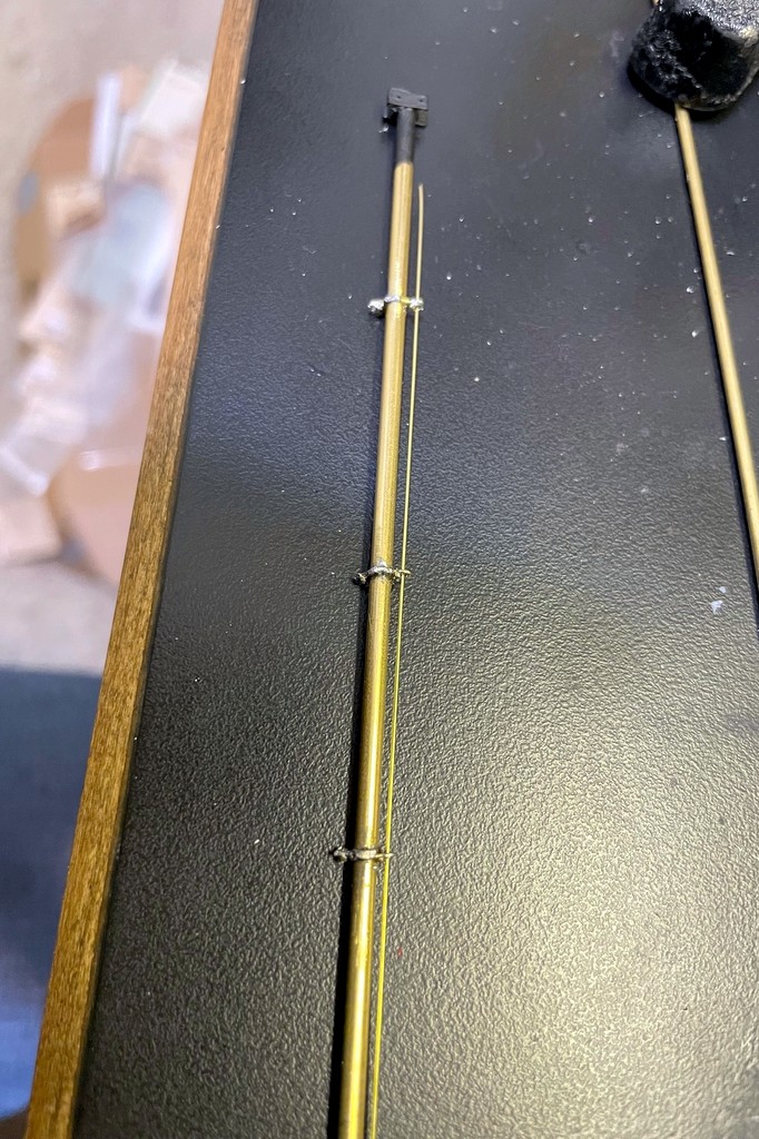
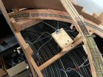
The first step of the handbrake is to locate where you want the brake, drill a hole, and insert a brass rod sleeve for the brake wire
This method is overkill if you just want to hold cars in place on a siding. For this I recommend a drop of CA, a piece of monofilament line sticking up through the tracks, or the end of a soft brush if more strength is needed–I use all of the above for holding cars in place when set out. I use the method here where I need brakes sometimes and free rolling other times, so the first thing you need to do is figure out where you need brakes. I once heard a story about a design presented to a university for a new campus that didn’t show any sidewalks. When the dean of the university asked the designer why there were no sidewalks, the designer replied “wait a year after the campus is open, then you’ll know exactly where the sidewalks need to go based on the trails through the grass.” So, where do I install brakes? Wherever I find I need them when operating trains–a question I also pose to my operators after every session: “is there anywhere you wished you had handbrakes but didn’t.” Generally speaking, they’re needed anywhere a crew will need to leave cars on a grade for a period of time to conduct other work. Since I’ve got lots of grades on the layout, I’ve currently got five handbrakes installed on the lower level alone.
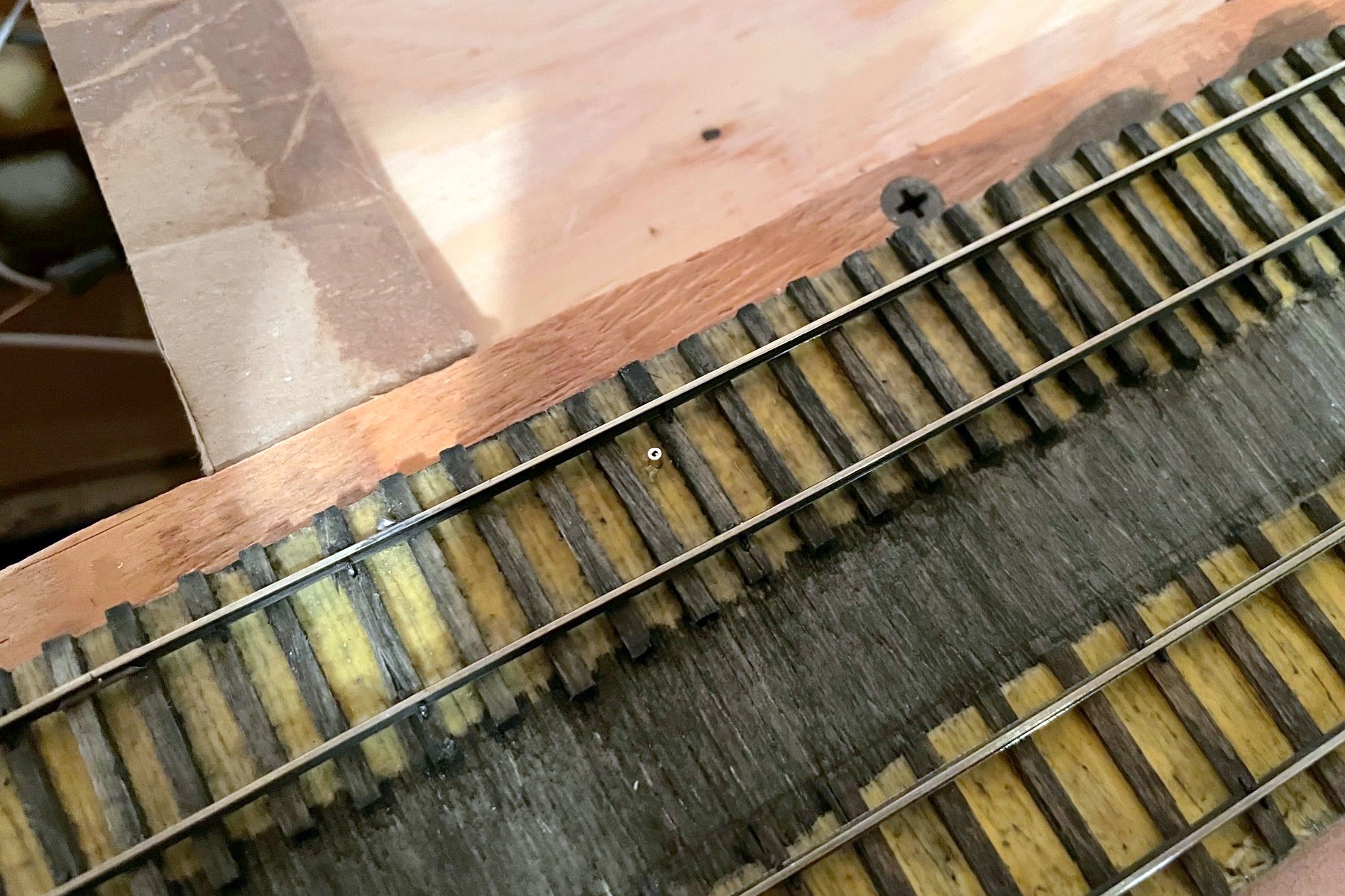
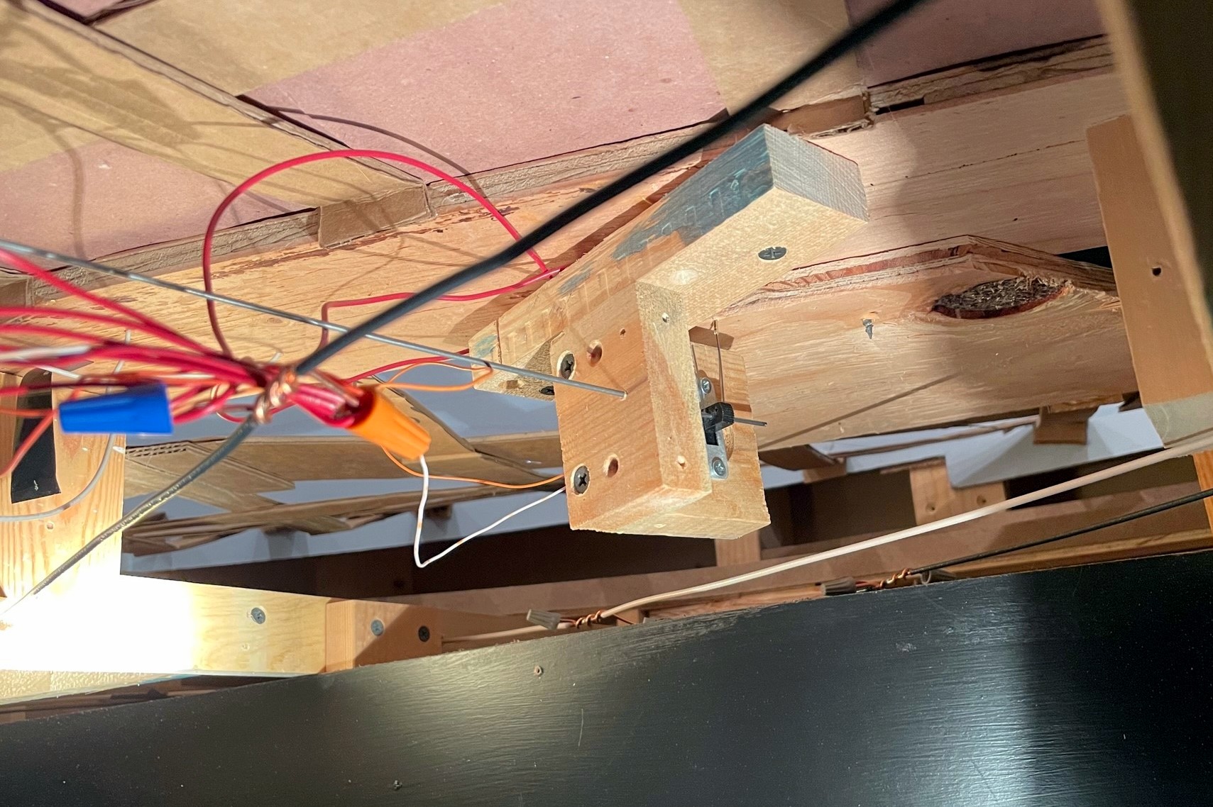
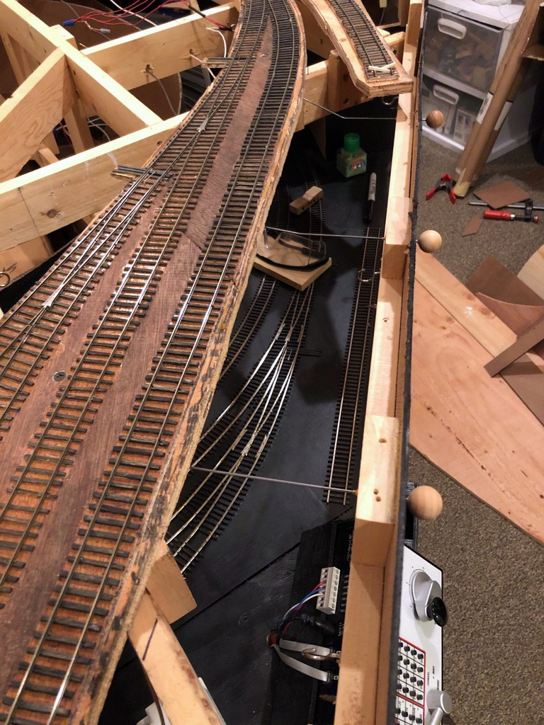
The concept of these fascia-controlled handbrakes is simple: install a movable piece of strong wire between the rails tall enough to hold an axle with a mechanism to retract it when not in use. Once you know about where you need brakes, mark that spot between the rails, and make sure the area underneath is clear enough to install a brake mechanism. Remember, the brake can really be anywhere along a string of cars, so if your ideal spot is not to ideal under the layout or on the fascia, just move it a few inches. I use 1/16″ brass tube as a protective sleeve for the .025″ steel music wire I use as the brake, so once I find a spot, I drill a vertical hole between the ties for the brass rod. I like to offset the rod about 1/4-1/3 between the rails to avoid interfering with truck bolsters (coupler trip pins will also be an issue for those who use them… in fact, a similar mechanism might work for uncoupling too, hmmm…).
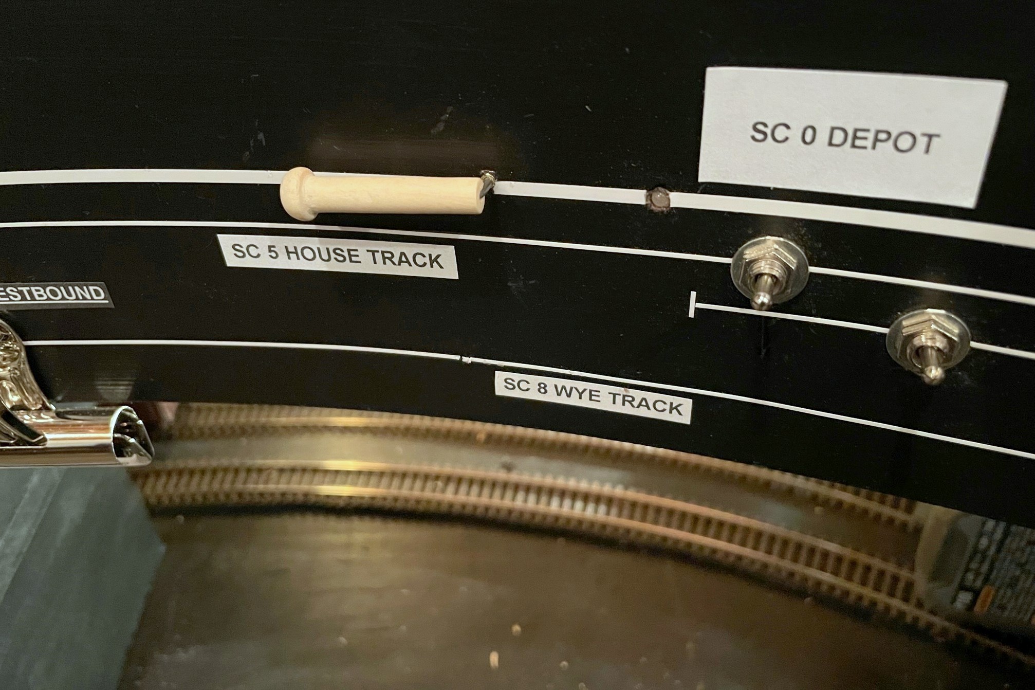
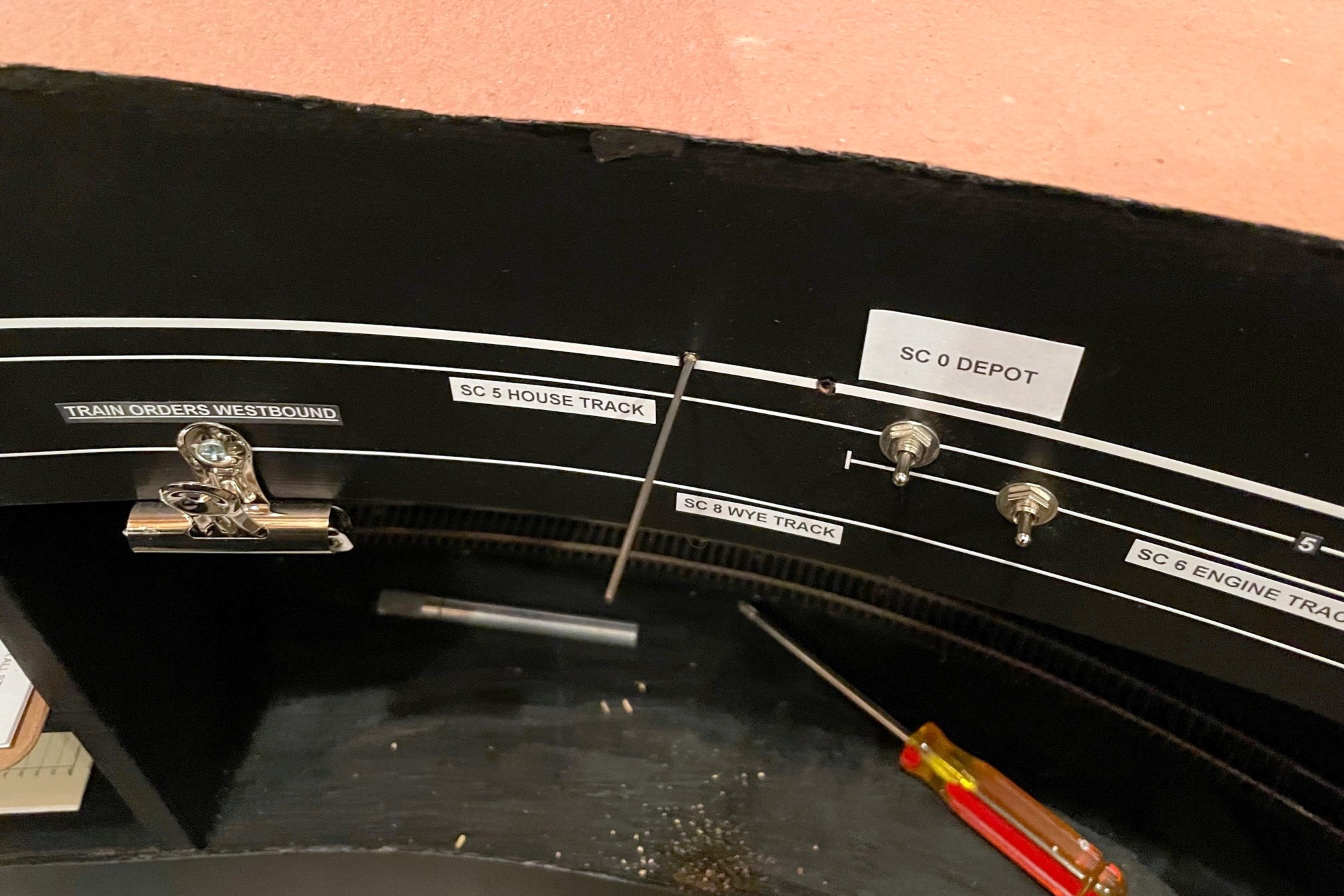
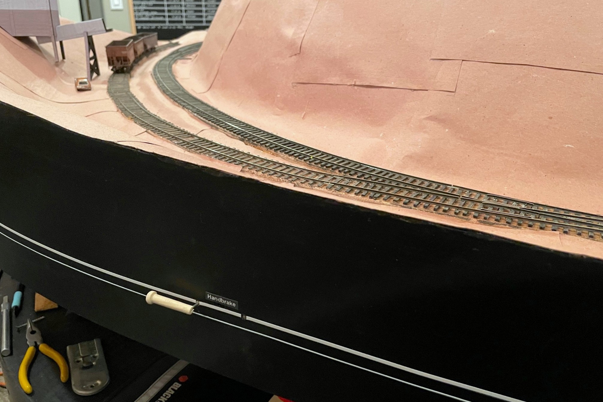
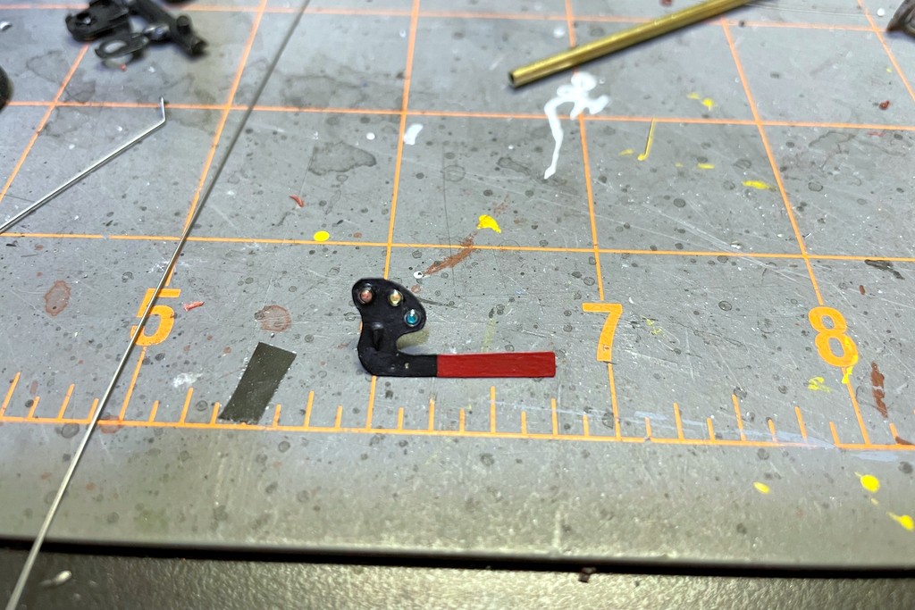
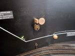
Here’s the finished control in the “off” position (in line with track)
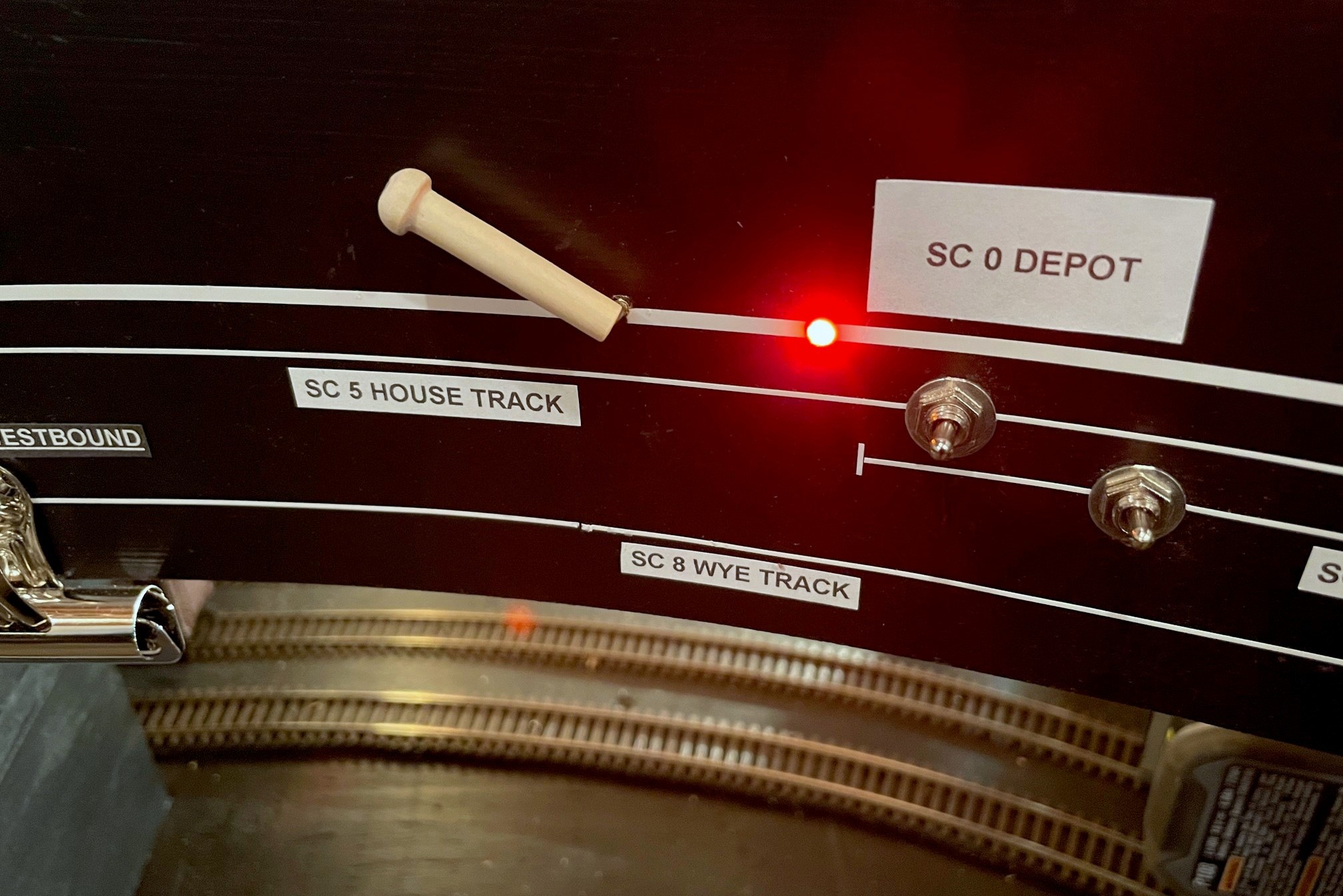
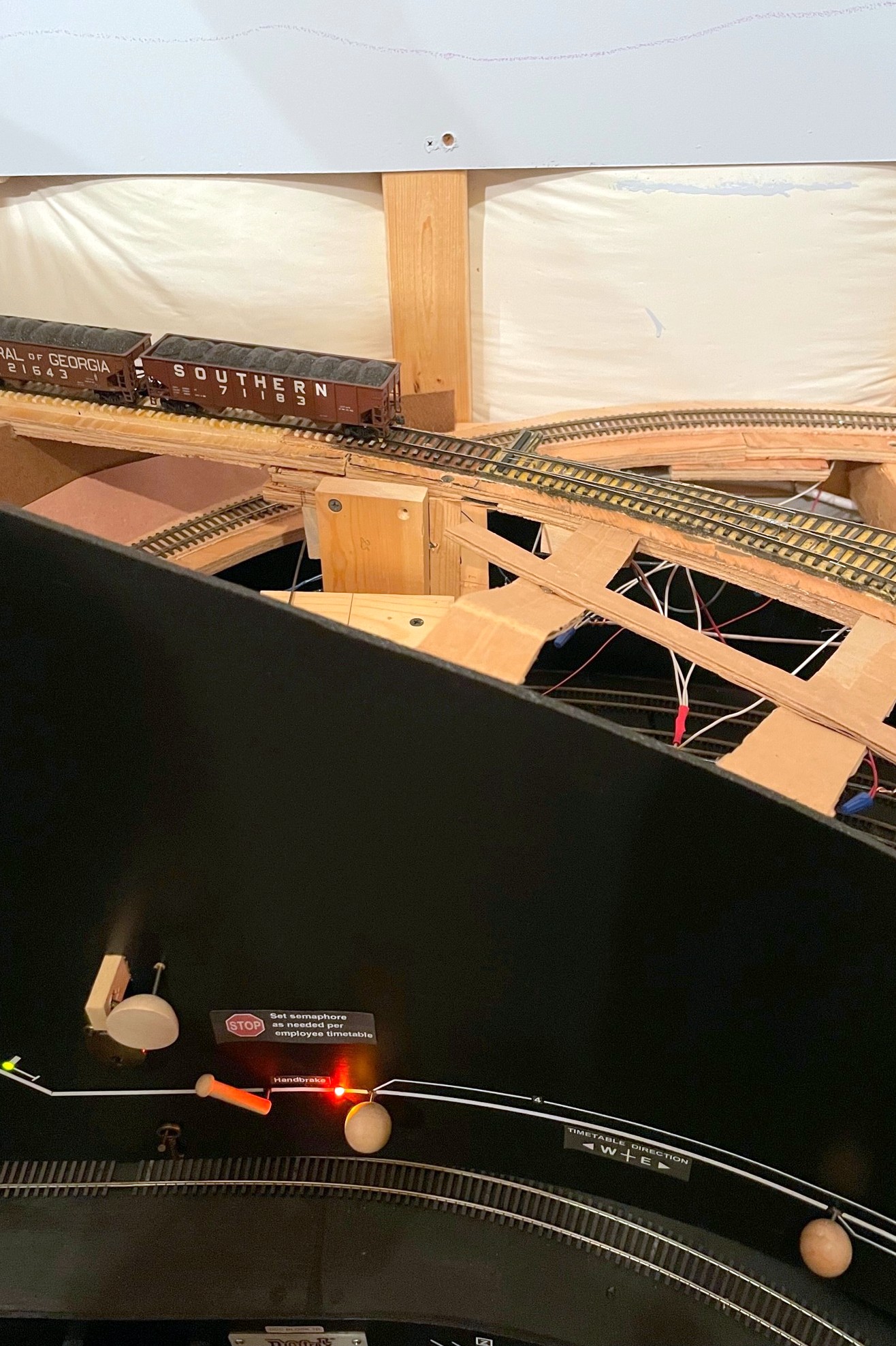
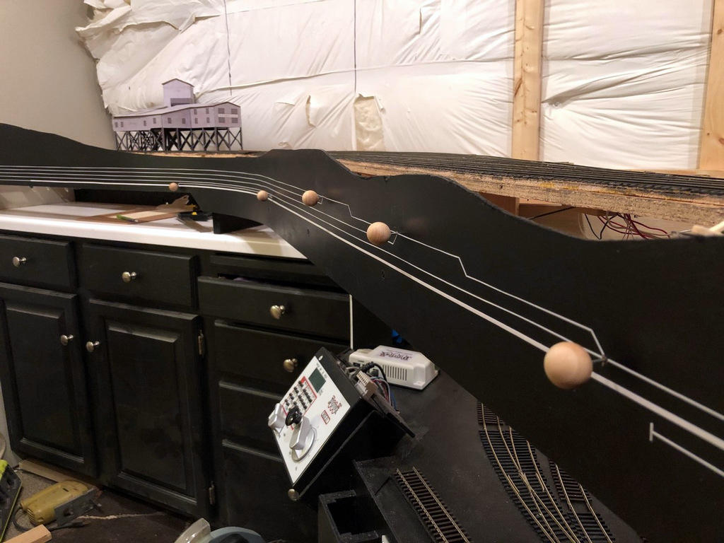
If you’ve followed me for a while, you know I’m a big fan of manual controls using slide switches–I use them for turnout controls, semaphore controls, and now handbrakes. You also know I’m a stickler for creating a fascia where the controls make sense and aid an operator instead of confusing them. In the case of the handbrake, I wanted it to be easy for operators to see when the brake is “set” and when it is retracted, so I settled on a control lever that lies in-line with the track when retracted and sits at a sharp angle when “set.” Just for good measure, I also use a bi-color LED to illuminate amber on the fascia representation of the affected track when the brake is set to help mitigate inadvertently running into a brake with the delicate footboards of a super-detailed locomotive (been there, done that).
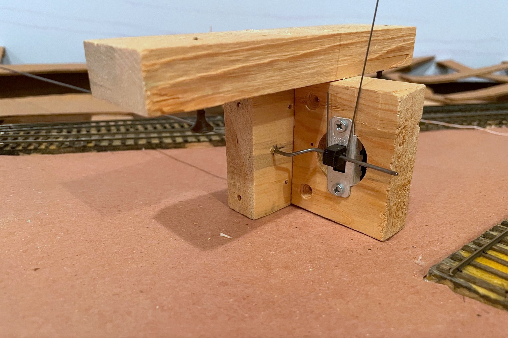
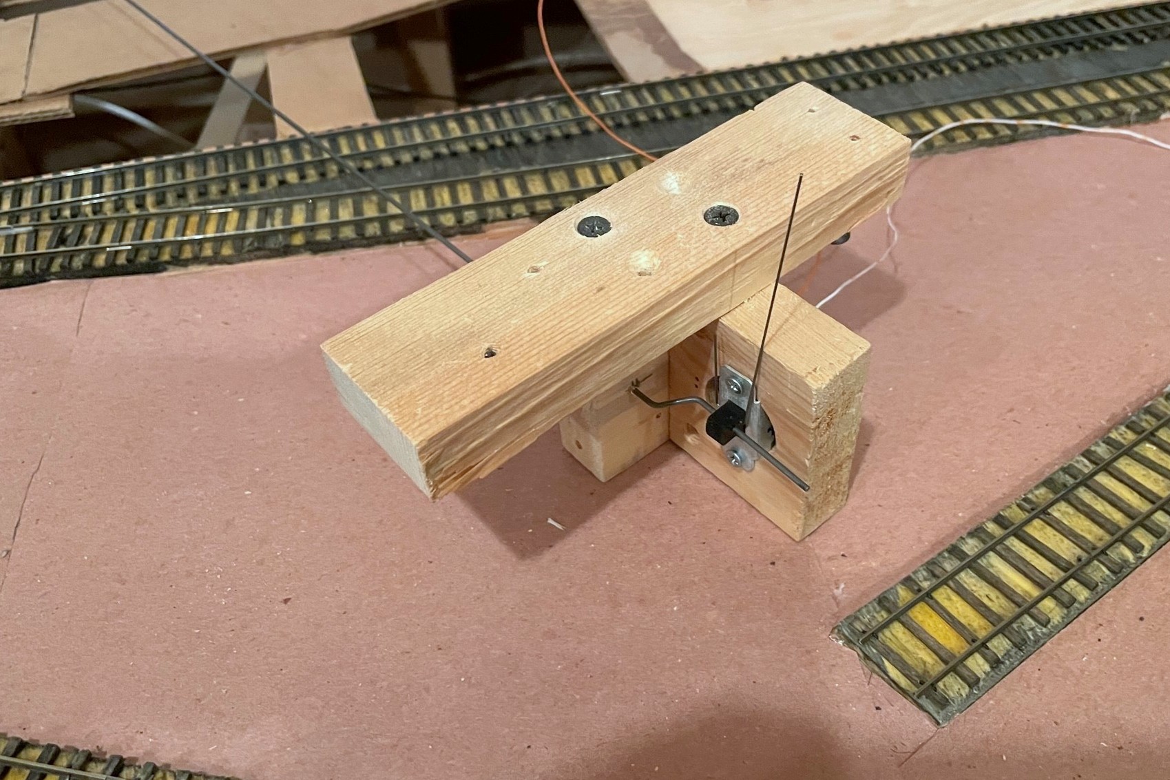
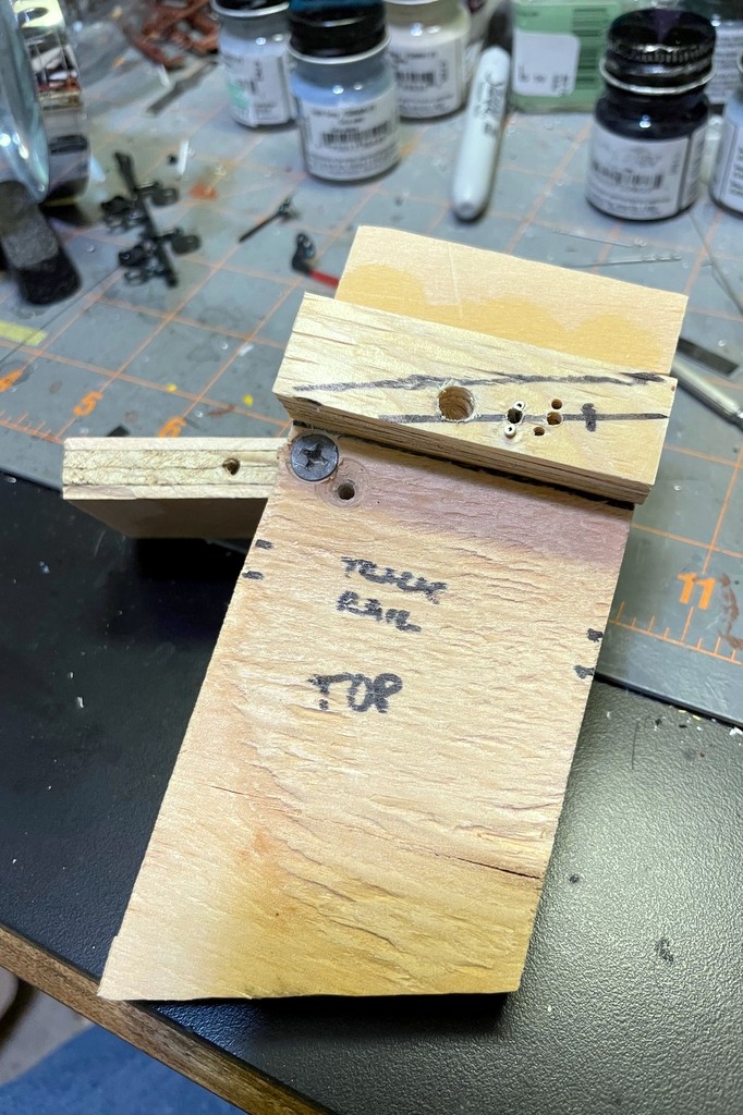
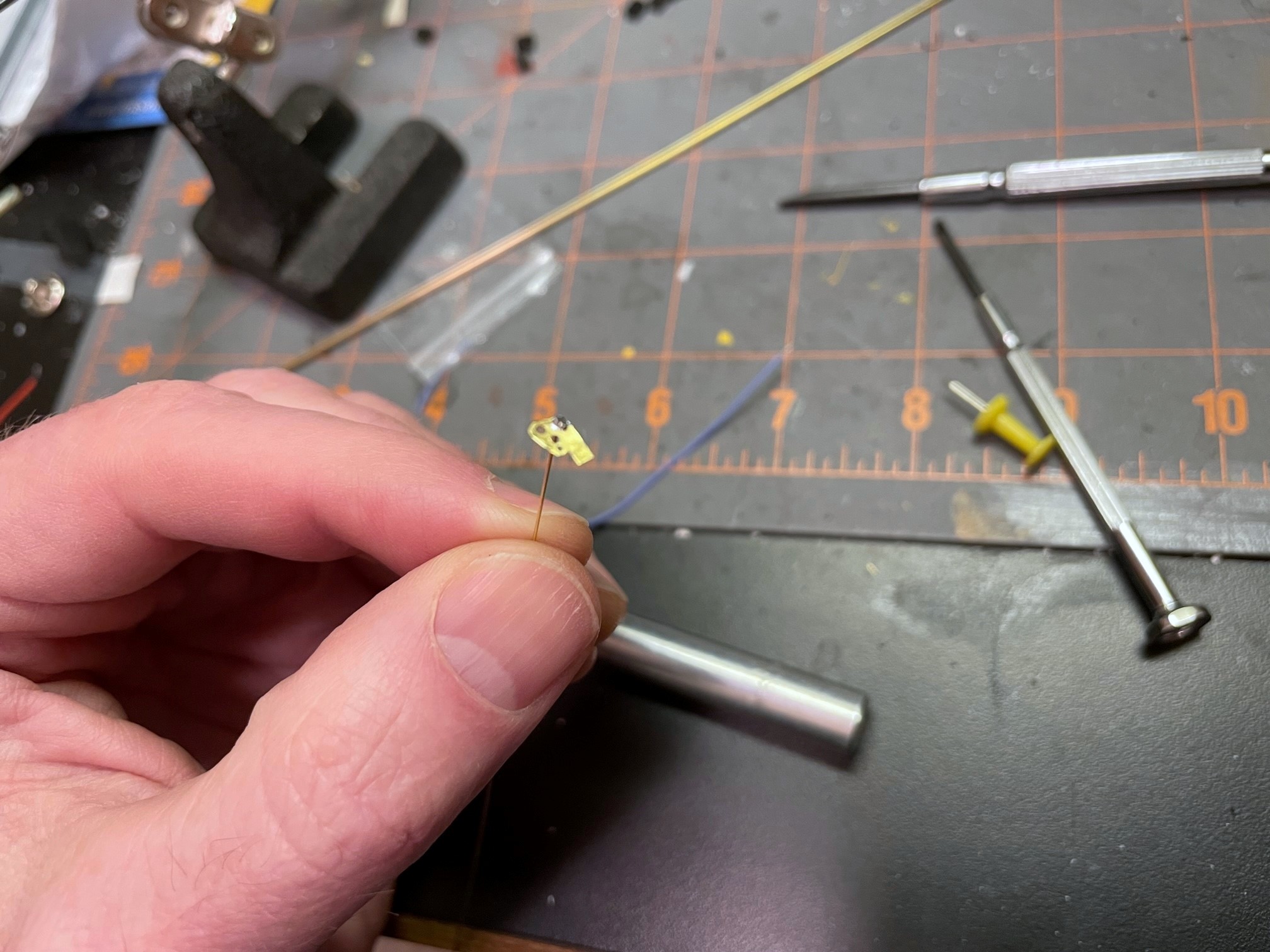
Here’s the completed brake assembly with three pieces of wood, DPDT slide switch, brake wire (vertical), and control rod (horizontal)
For the brake mechanism, I use a vertically mounted slide switch (DPDT in this case) with a 3/16″ throw–this is just enough to catch the axle of a 36″ wheel in HO scale when extended and still retract to almost rail height when recessed. The brake rod itself is a piece of .025″ music wire bent into a squared-off “J” shape running through a hole in the slide switch–initially, make this piece long enough that it will stick up about 1/2″ or more above the rails when in place. The control mechanism is a piece of thick steel rod (.062″ music wire) with a bell crank bent at one end. Th rod should be cut about 3″ longer than the distance between the brake’s track location and the location of the control on the fascia. The bell crank is offset about 1/4″ from the rod. As you can see in photos, I drill a hole in a piece of 1×3″ board centered on the slide switch and offset about 1/4″ laterally for the control rod to pass through (lined with 3/32″ brass tube for smooth operation). I also bend the bell crank at 45-degree angles instead of 90 as this allows me to make adjustments to the crank offset in either direction, shorter or longer. The structure for the mechanism is typically three boards: 1) the slide switch board with a large hole drilled out for the switch (mounted with screws), 2) the control rod board mounted 90 degrees to the switch where the bell crank is secured, and 3) the attachment board on top to make it easy to mount to the plywood sub-roadbed. I use 1×3″ pine for most of my pieces, but I may use different thicknesses of attachment plates to get the control rod at the right height for the fascia control–the brake wire can be really tall and still work, so better to have the mechanism hanging lower than to have to curve the control rod to the right height. Once I’ve got the three boards assembled with 1 1/4″ drywall screws, I disassemble it, insert the bell crank end of the control rod, insert the bell crank into a hole drilled in the slide switch, adjust the bell crank as needed for smooth operation of the switch, and reattach the boards with the screws.
The left is the front side of the assembly that will face the fascia–note the brass rod sleeve in the wood where the rod goes through
For the fascia, I drill a hole for the 3/32″ brass rod sleeve as close to horizontal as I can get it and pointed directly at the brake location on the track. I pick the spot on the fascia that allows me to do this while keeping the control rod as perpendicular as possible to the fascia (you don’t want the control rod coming out of the fascia at a strange angle if you can help it). The LEDs are nice but not necessary, but this is the step where I drill the holes, about 1″ behind the brake control. I like to drill the hole through the fascia the exact size of the LED bulb and then use a second larger bit from the back side of the fascia to create a space for the rest of the LED–this keeps the LED from popping out the front of the fascia. I use bi-color red/green LEDs which glow a nice reddish amber when hooked up to AC (e.g., DCC track bus), and I attach one lead to one side of the track bus (with a 470K resistor), the other lead to the “up” position of the slide switch, and a third wire from the center position of the slide switch to the other side of the track bus. Super simple.
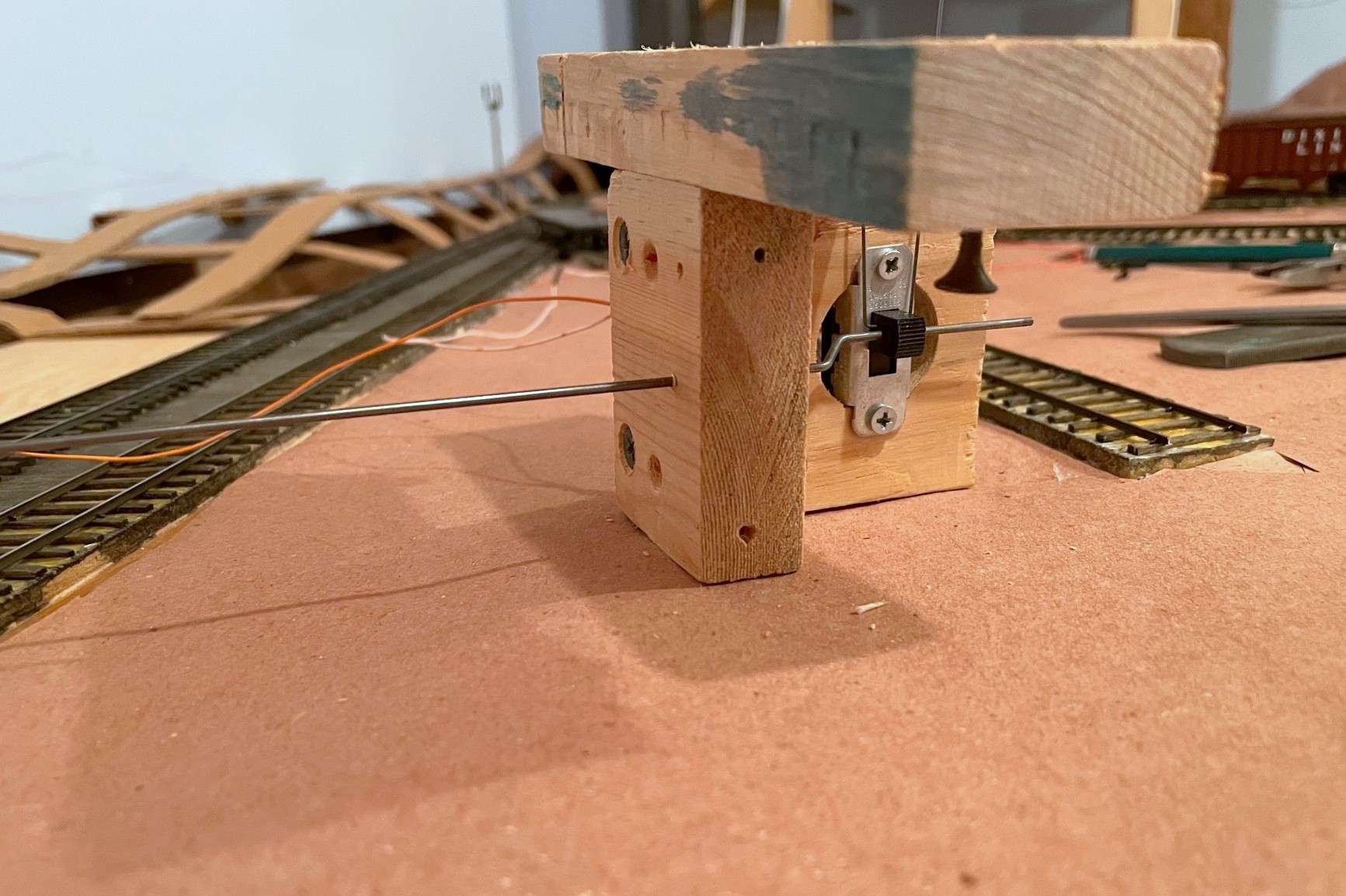
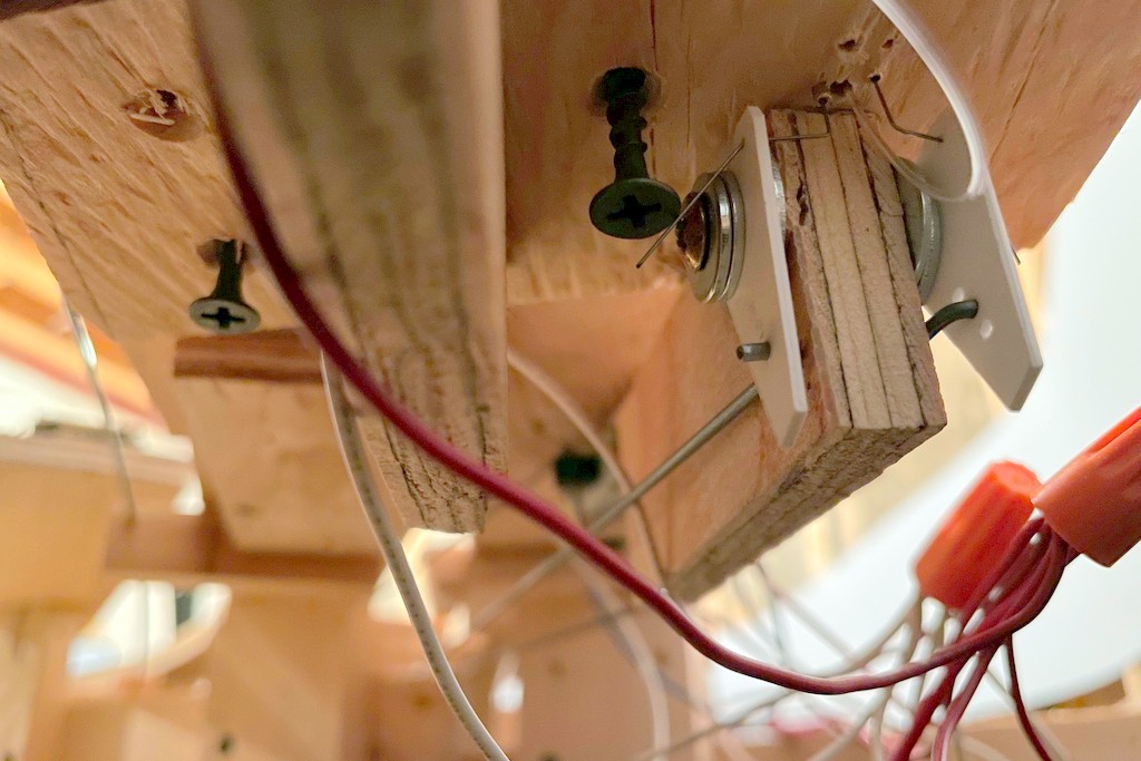
Here’s the handbrake mechanism installed under the layout–the control assembly should orient to the fascia and not the track
Mounting the switch mechanism is a bit of a pain and requires some planning and patience. From under the layout, I run the control rod through the fascia. Then I find the brass rod going up through the tracks and insert the brake rod (it helps if the brass rod is long enough to protrude beyond the plywood of the sub-roadbed). With the mounting screws on the attachment plate ready to go (screwed in so they’re almost through the board), I gently move the mechanism around until the brake wire is more-or-less vertical, the switch operates freely, and the control rod is as straight as possible between the fascia and mechanism. The mechanism is oriented to put the rod and switch perpendicular to the FASCIA rather than the track (angle relative to track doesn’t matter here). Once I’m happy with the placement, I run the mounting screws into the sub-roadbed.
With the brake in the RECESSED position, bend the control rod parallel to the ground
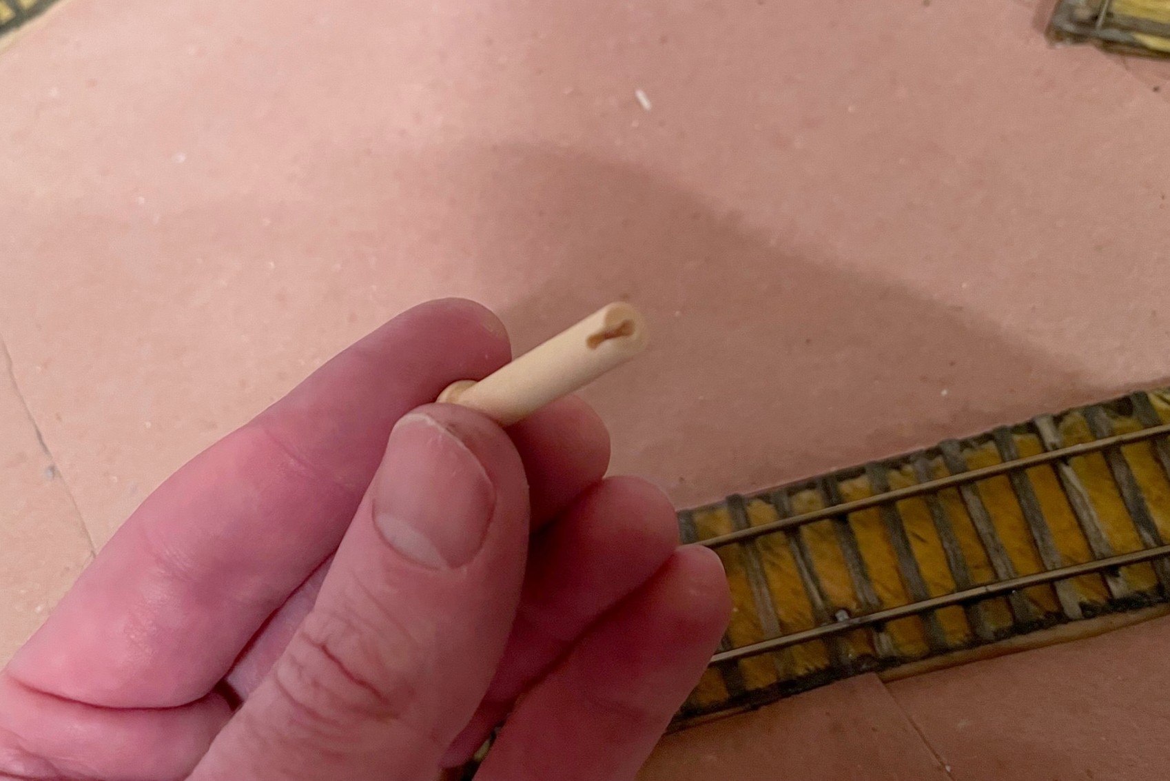
On the fascia side, I now have about 2″ of control rod sticking out. With the slide switch in the DOWN position, I then grasp the control rod with a pair of needle nose pliers flush with the fascia so the bend will be about 3/16″ from the fascia and use my hand to bend the control rod to align with my track diagram (horizontal) in the direction of the bell crank so that “up” on the control = “up” on the brake. My convention is to face the controls and bell cranks to the left, but either works. At this point, I have the leverage to test the mechanism and fix any issues. If all is good, I use a Dremel cut-off wheel to cut the end of the control rod so about 3/4″ beyond the bend. For the control lever, I use a wooden 1 3/8″ “axle peg” which can be found at any large craft store–it’s admittedly an odd shape, but it’s distinct, easy to find, and easy to use. I insert the pegs into a vice and drill a hole the exact size of the control rod about 1″ deep into the center of the peg, then drill another hole in the side about 1/8″ from the flat end into the first hole and use an X-Acto blade to create a notch between the two for the 90-degree bend in the control rod. The peg is usually a press fit onto the control rod.
The brake wire should initially be longer than required in the recessed position
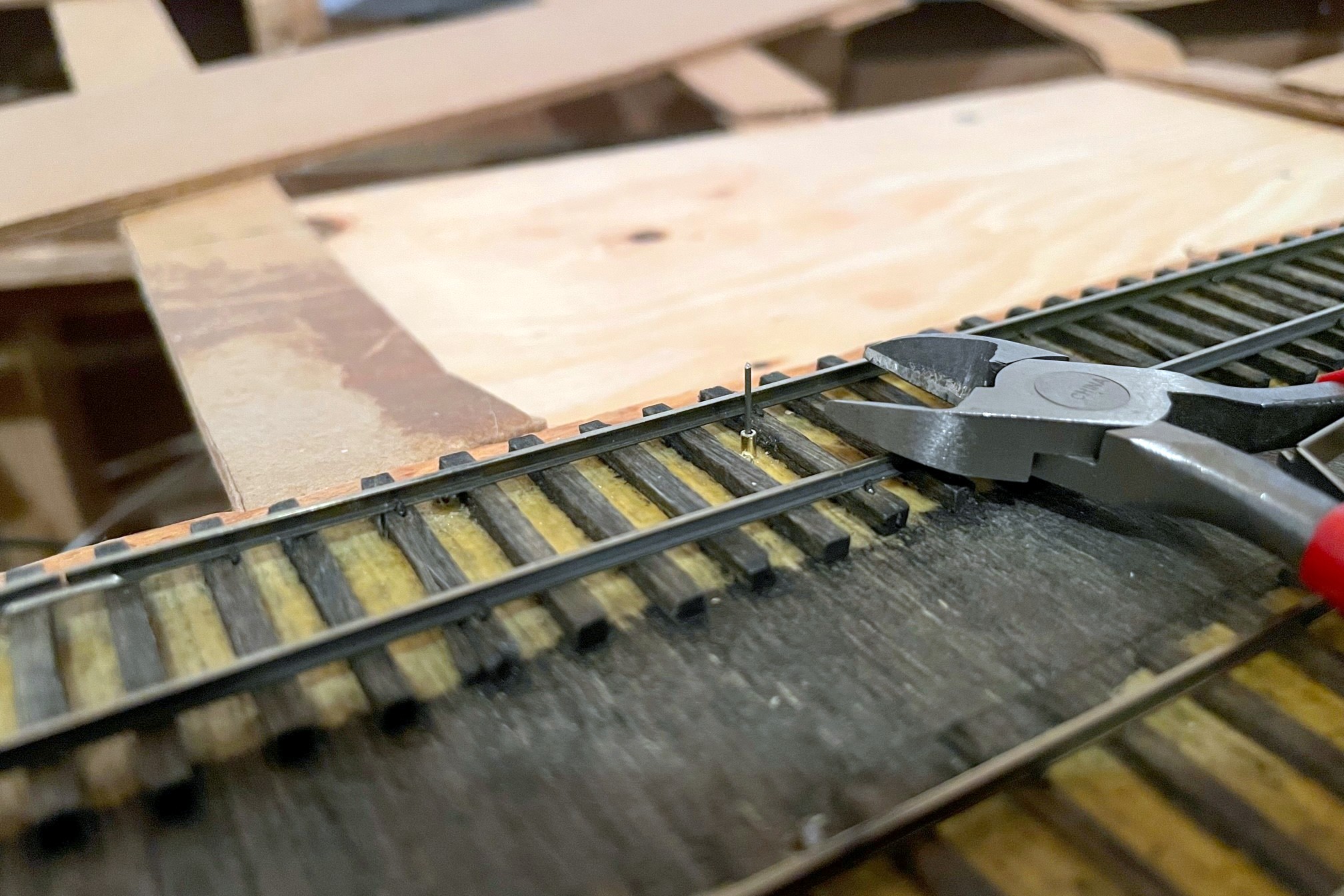
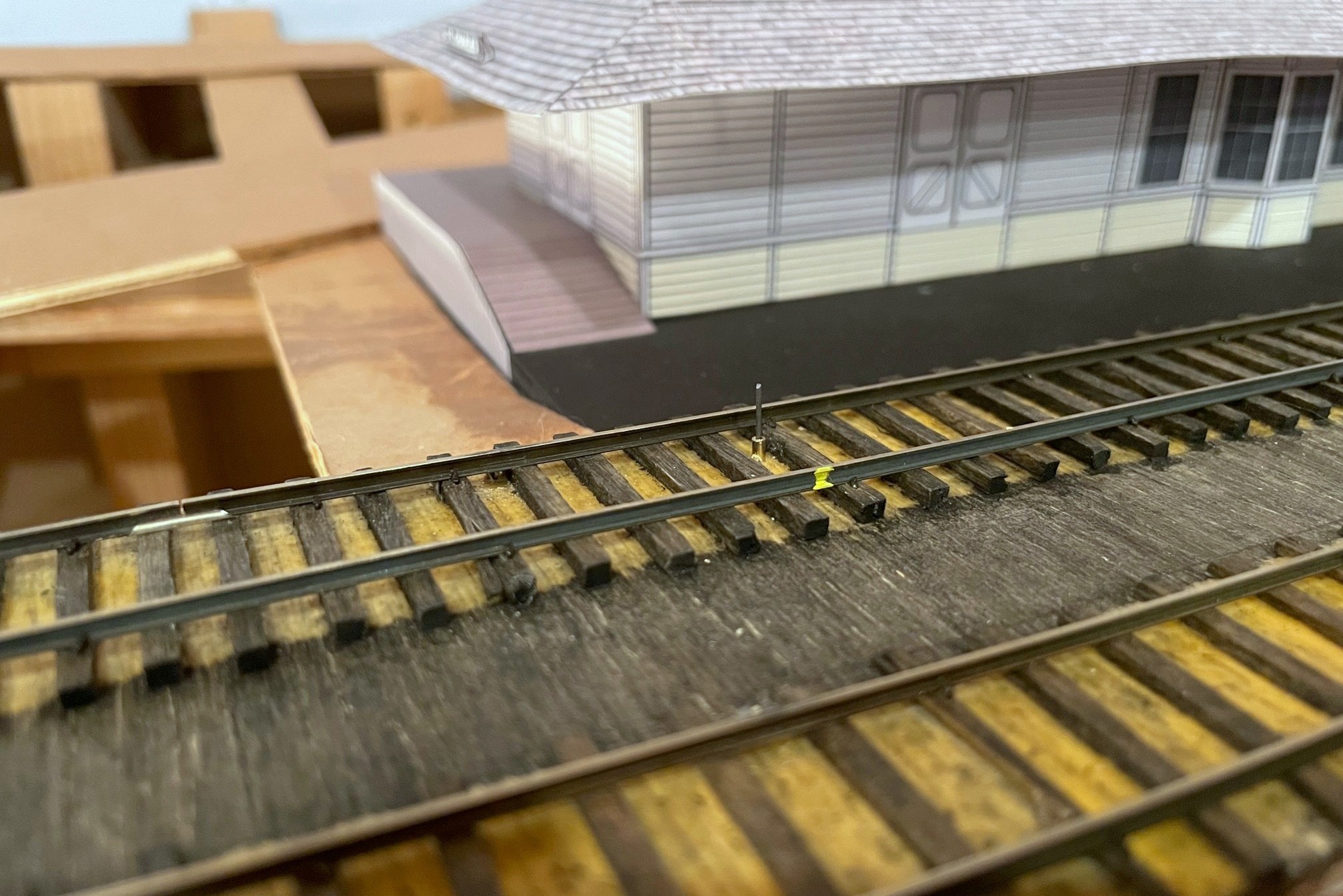
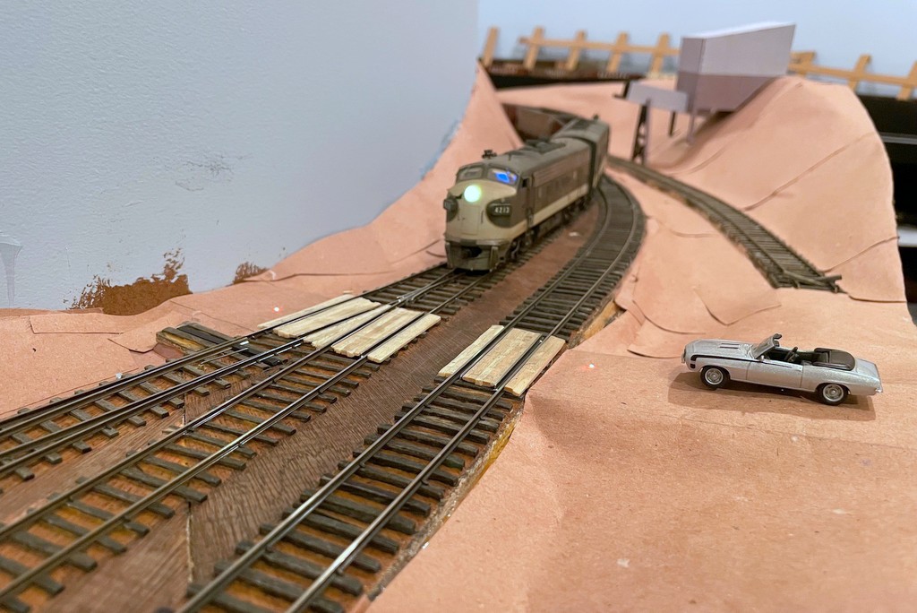
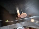
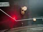
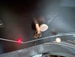
The final step is to trim the brake wire. I’ve found if I use a pair of wire cutters at rail-top level when the brake is in the DOWN (recessed) position, it is low enough for all my locomotives to clear and extends high enough to catch all my axles when needed. Because the wire’s location can be tough to see (especially when cars are over it), I use a little dab of yellow paint on the outside of the rail to indicate where the brake wire lives for easy spotting by crews.
The brake wire can be tough to see with cars on top of it, so I use a little dab of yellow paint on the rail to help operators know the brake location
I’ll also share some “lessons learned” for using this type of handbrake:
The brake will find your lowest-clearance locomotive and keep it from moving until you trim the brake wire–remember this locomotive and use it to test all brake installs
If you try to pull a string of cars when the brake is engaged, you WILL bowstring every car between the locomotive and the brake off the rails (sometimes violently)
If you leave the brake “up” and roll cars into it, they will bounce back quite jarringly upon hitting the brake
If you don’t pay attention and activate the brake under a truck bolster or low-hanging part of the car, you WILL raise the car off the rails and derail it (or topple it)
Other than these “gotchas,” I’m very happy with the operational possibilities these handbrakes add to the model railroad!
The St Charles Switcher crew sets the handbrakes to leave a string of loaded hoppers on the grade while working the yard
The first step of the handbrake is to locate where you want the brake, drill a hole, and insert a brass rod sleeve for the brake wire
Here’s the completed brake assembly with three pieces of wood, DPDT slide switch, brake wire (vertical), and control rod (horizontal)
The left is the front side of the assembly that will face the fascia–note the brass rod sleeve in the wood where the rod goes through
Top view of the handbrake assembly–the top board helps to mount the assembly securely under the subroadbed
Here’s the handbrake mechanism installed under the layout–the control assembly should orient to the fascia and not the track
The control rod should protrude through the fascia at least 2″
With the brake in the RECESSED position, bend the control rod parallel to the ground
I use a wooden axle for the control rod and drill out a hole the size of the control rod along with a notch on one side
Here’s the finished control in the “off” position (in line with track)
Here’s the handbrake control in the “on” position–the LED helps alert operators that the track is not clear
The brake wire should initially be longer than required in the recessed position
With the brake wire in the recessed position, trim it to just above rail height with wire cutters
The brake wire can be tough to see with cars on top of it, so I use a little dab of yellow paint on the rail to help operators know the brake location
Here’s another handbrake on the main at a location where crews have to leave their train to work cuts of cars through a short run-around just ahead
Here’s another handbrake on a 3 percent grade above St Charles Yard–I use this one to set cars above the yard and use gravity to route them down the right track, just like the prototype would often do
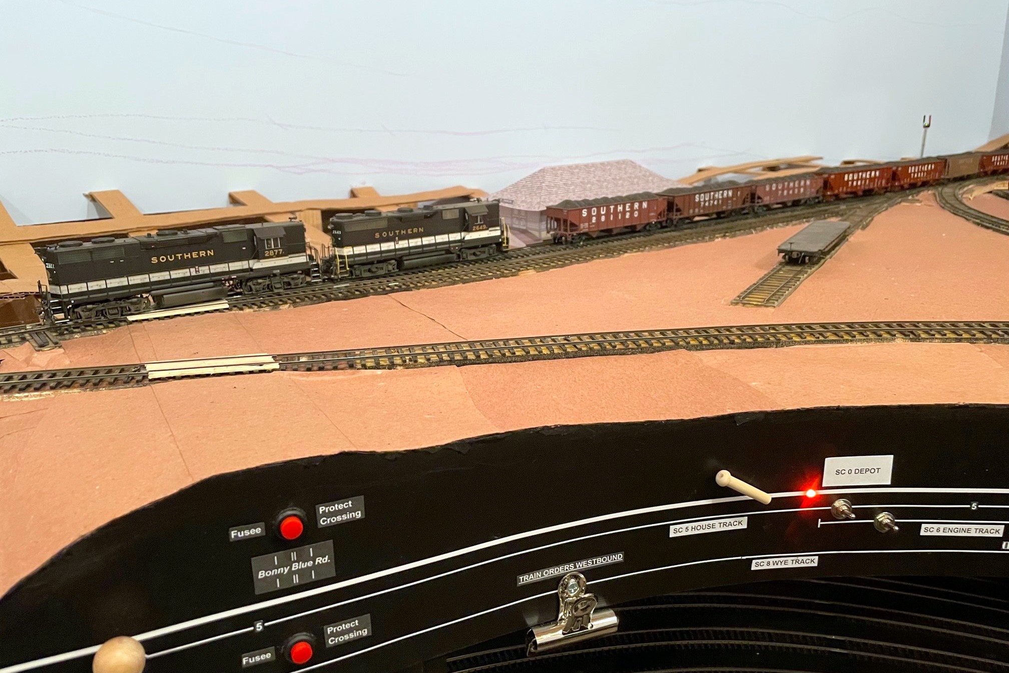
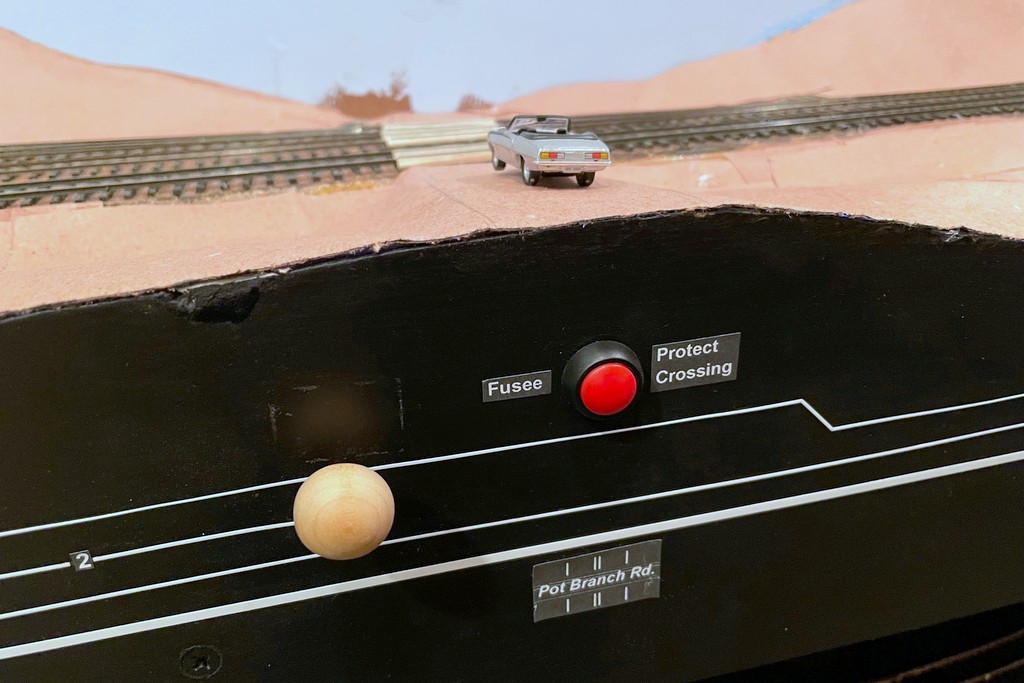
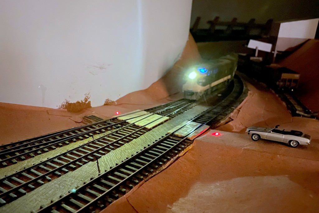
The St Charles Switcher crew throws down a couple fusees to protect the Pot Branch Road grade crossing near Mayflower
I enjoy trying to copy every element of prototype railroading I can… as long as there’s at least an element of fun in it. When I saw this short video showing a Western Maryland crew dropping fusees (pronounced “fyoozees”) to protect a grade crossing, I started thinking about how I might model this. Fusees are used by railroads for many purposes including dropping them on tracks to warning following trains of their presence–because of this purpose, fusees are designed to burn for a set time, commonly 10 minutes. Fusees can also used to protect grade crossings that don’t have flashing lights like the one in the WM video, especially when it’s dark or posting a flagman wouldn’t be practical or safe. Since I want to model nighttime ops, and I haven’t made any HO scale flagmen to post yet, I decided I wanted some simulated fusees to protect the handful of crossings I have on the layout.
My first attempt was pretty simple and economical, just two fiber optic cables embedded into the “road” (it’s just paper and cardboard at this point) on either side of the grade crossing routed to a bi-color LED that I connected to the DCC track bus (creates a reddish orange glow) and a simple SPST push-button switch. To keep the fiber optic cable from falling through the road, I melted the end into a mushroom shape by holding it near a hot soldering iron. The other ends were taped together and inserted into a piece of shrink tubing around the LED. It was functional enough to protect the crossing, but I really wanted a way to 1) put the fusees on a timer, and 2) make them look a little more realistic.
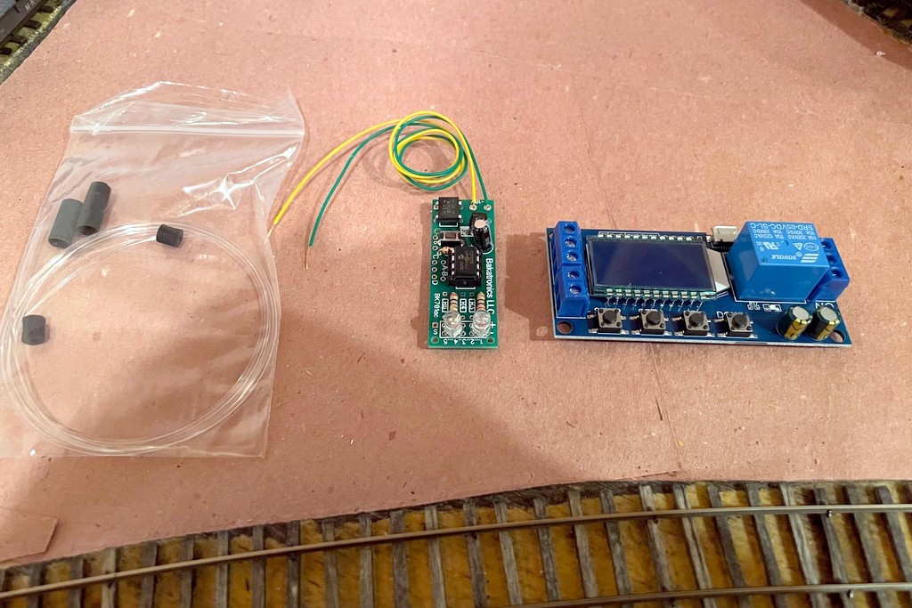
The basic parts to make a simulated fusee including fiber optics, the Bakatronics flares / fusee circuit, and the timer circuit
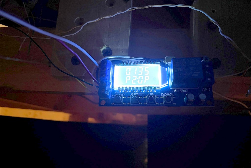
The timer issue was solved by searching Amazon and looking at a lot of different timing circuits. I finally settled on this one, though it’s probably overkill. I like it because you can choose one of several timing modes (fun to play with for other projects), you can set the timer for however long you want to keep the relay “on,” and you can easily see the timing settings on the display. To make them more realistic, I started with an internet search for “model railroad fusee,” and after chasing through some links in model railroad boards, I discover the Bakatronics BK-111 “Simulated Flares / Fusees Kit.” It looked promising, especially since it’s designed to power two fusees that “light” and extinguish several seconds apart (like one person is walking a short distance between lighting them, just like a grade crossing). I ordered two just to make sure it would work, and I was not disappointed! When activated, they “light” at different times, flicker independently for a while, then the first one goes out, then the second with a nice slowly diminishing burn out… really cool looking!
The fusees are controlled with a simple momentary SPST switch on the fascia
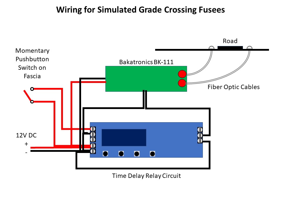
The Bakatronics fusee circuit is designed to work with either a momentary switch (stays on for about 30 seconds) or an on/off switch (stays on as long as the switch is closed). Instead, I wired the fusee circuit to the timer circuit so I could set the time the fusees stay lit exactly, and all the operator has to do is push a button once. I use a 4:1 fast clock, so a 10-minute burn should last about 2.5 minutes / 150 sec. The Bakatronics circuit add some time on its own, so I found a setting of 135 sec on the timer keeps the fusees lite for about 10 scale minutes, and like the prototype, the crew only needs to worry about whether or not to put down another set of fusees (push the button again) if the first set “burn out.” Both the timer circuit and fusee circuit run off a ~12V DC bus I have running around the fascia, previously to power semaphore lights. Here’s a video of the fusee in action…
We used these on my last operating session, and I thought they added a neat bit of prototype thinking for the crews–we had to think about protecting the crossings while moving the trains, and the flickering fusees gave a visual representation of the action taken. I can’t wait to try them at night when I’ve got the final lighting installed!
The basic parts to make a simulated fusee including fiber optics, the Bakatronics flares / fusee circuit, and the timer circuit
Here’s the end of the fusee pulled out of the “road” for better viewing… just the end of a fiber optic cable melted into a mushroom shape
Here’s the powered timing circuit showing mode “P2” (reset time if pushed again) and “135” second of “on” time once activated
The fusees are controlled with a simple momentary SPST switch on the fascia
A look at the glowing fiber optic cable under the layout that lights the fusee
The St Charles Switcher crew throws down a couple fusees to protect the Pot Branch Road grade crossing near Mayflower
The layout’s not set up for night operations yet, but once it is the fusees will look spectacular!
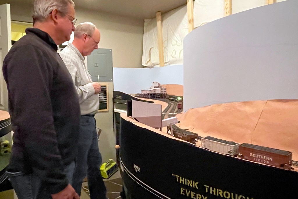
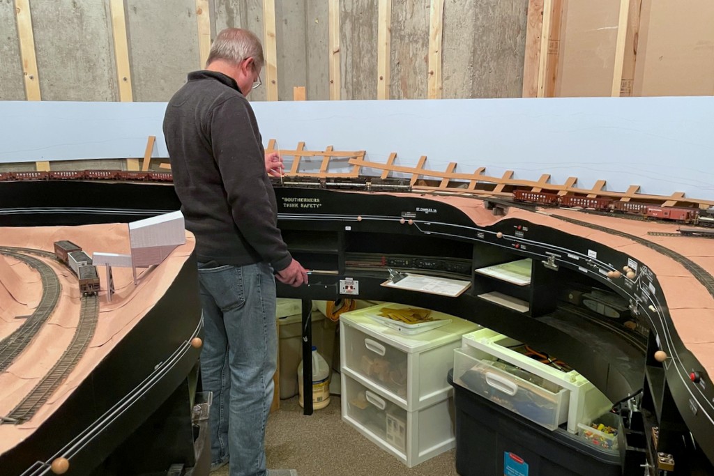
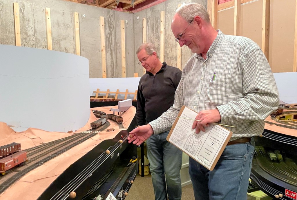
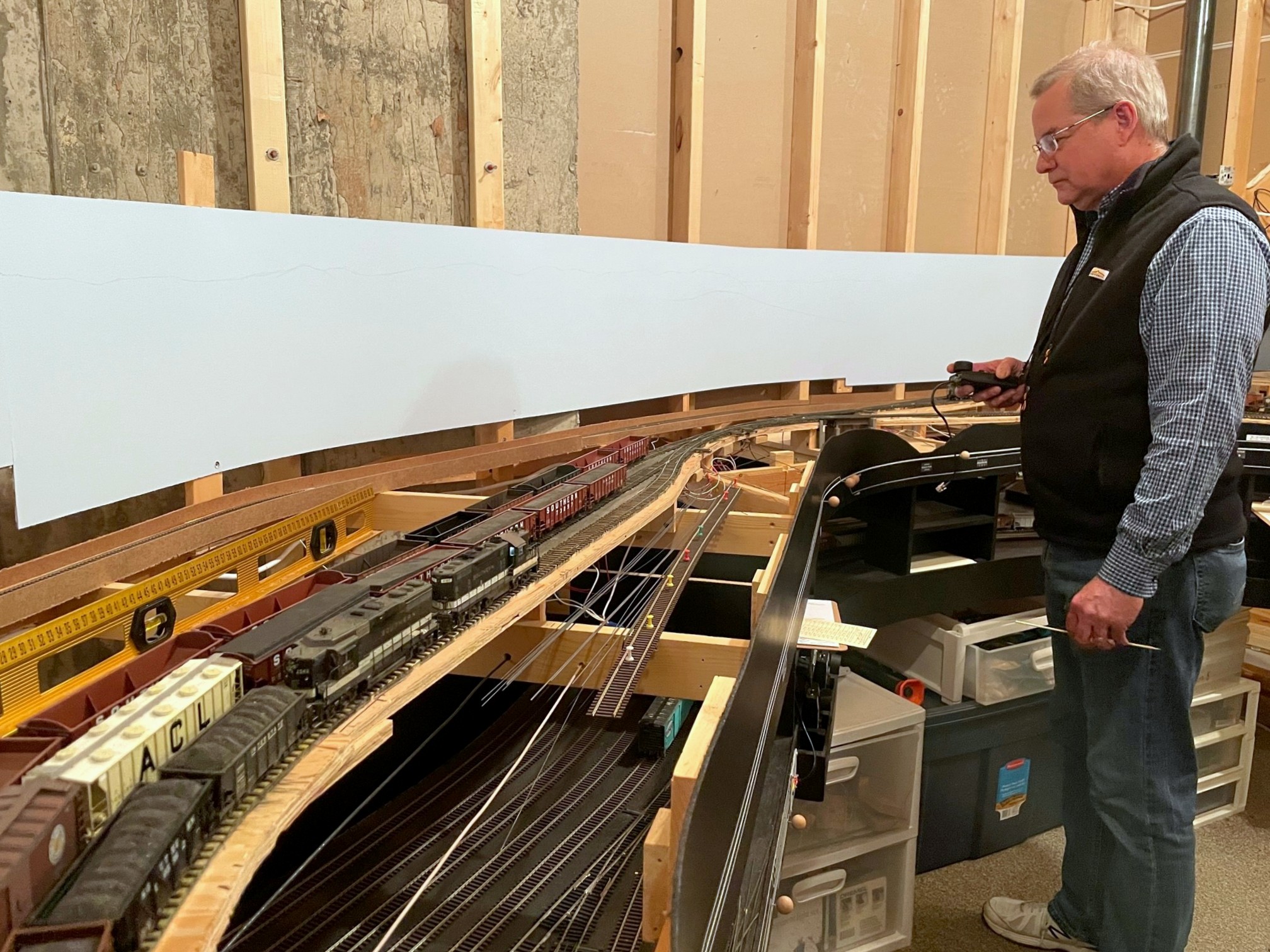
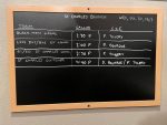
Patrick and Stuart work Mayflower with the St Charles SwitcherPatrick runs the St Charles Local figuring out how to get 10 pounds of cars to fit in a 5 pound sack
Or is it “operating session Aug 2, 1976?”… Regardless of the date, it was a lot of fun hosting two great friends, Stuart Thayer and Patrick Tillery. This was the first-ever 3-operator session on the layout, and despite only having one of the two decks complete, it still took the three of us the better part of three hours to run four trains. Part of that is because I know Stuart and Patrick are both experienced operators and prototype buffs, so we put some “veteran mode” rules into effect. In addition to the normal rules of “get the cars where they need to go,” “follow signals,” and “follow the timetable and orders,” we had to protect crossings (more on that in a later post), unlock/set/lock semaphores to protect the branches we were operating, cut cars to avoid blocking a new road across two yard tracks, and follow all blocking instructions including placing all loads ahead of empties.
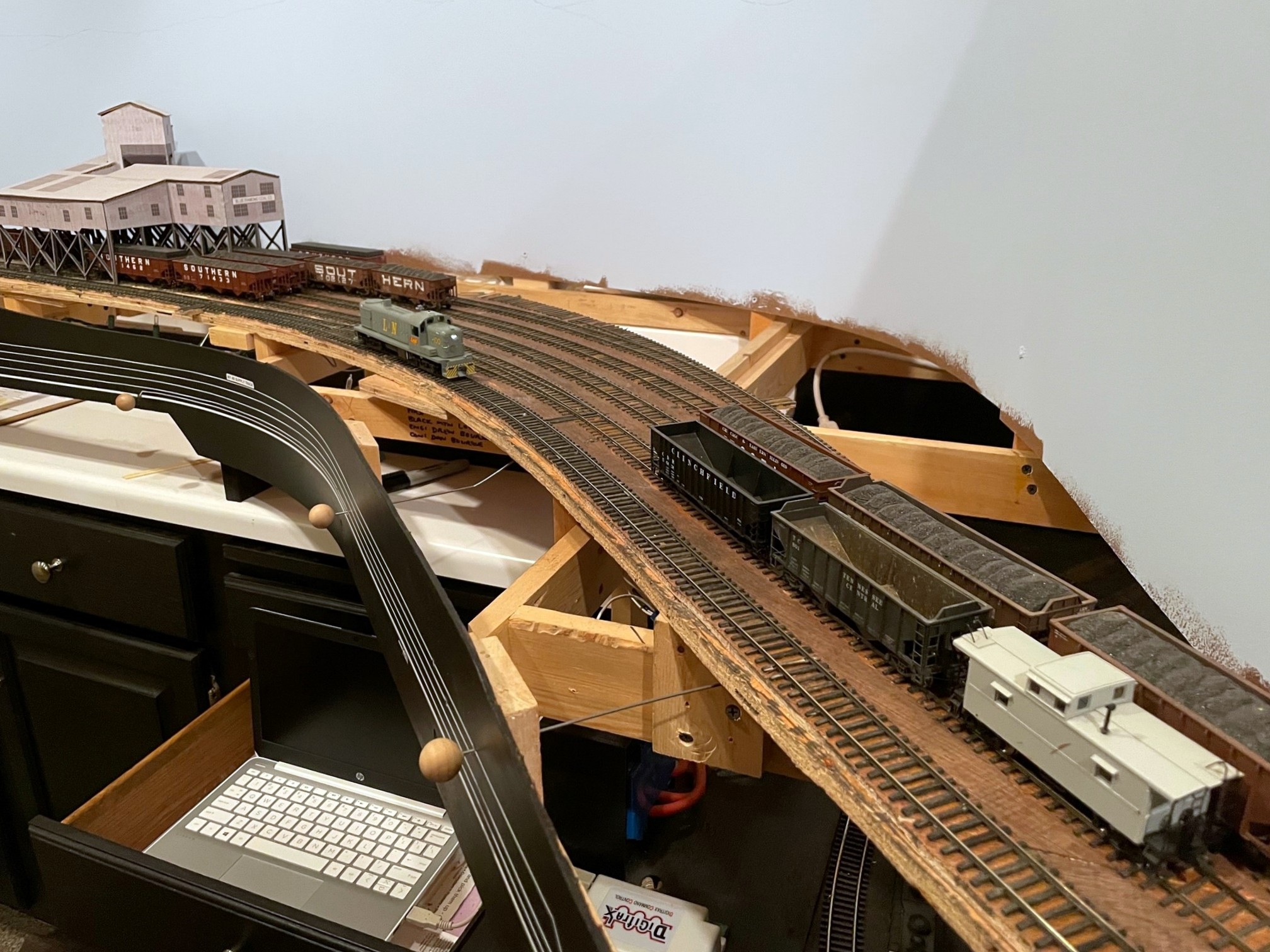
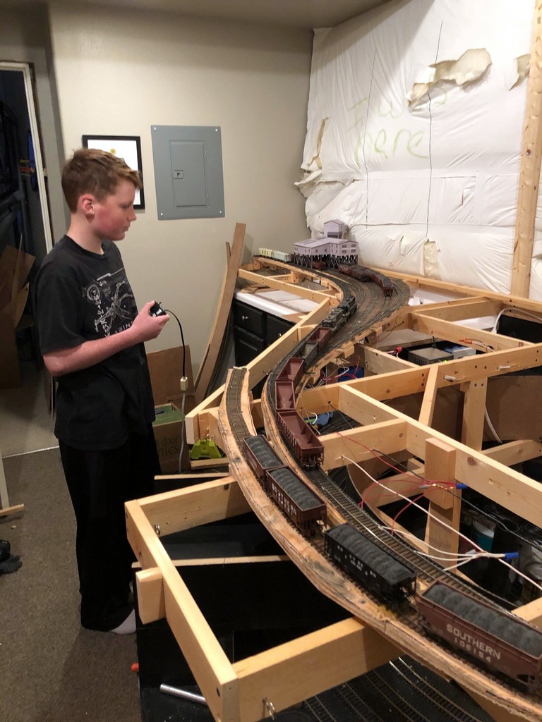
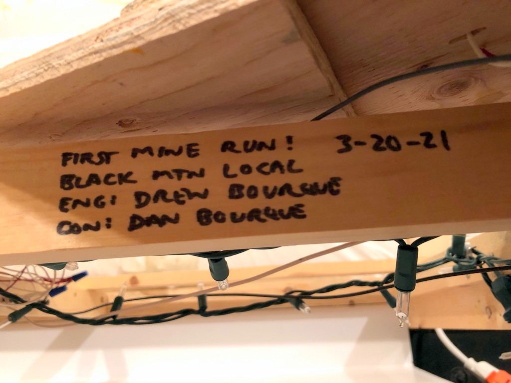
Trains included a “Black Mountain Local” that simulated bringing in the previous night’s haul from the non-existent upper-deck tipples, an L&N “CV Local” to handle the L&N’s trackage-rights agreements at two tipples, Train 61/60 the “St Charles Local” bringing empty hoppers out of Andover (staging) and returning with loads, and the “St Charles Switcher” working St Charles area tipples and the Baileys Trace Branch to Mayflower. With the “veteran mode” rules in effect, even the simplest of trains still took a while to operate. Just the movement of the Black Mountain Local out of the helix (including a stop to reset the semaphore) and blocking in the three-track yard took a full scale hour (15 minutes real-time). Despite the simplicity of the St Charles Local’s job (bring empties, pick up loads), the yard’s prototypically small size creates the need to use the tracks and wye creatively to swap out cuts, and the instruction that all empties (in this case empty covered hoppers) have to go behind the loads, drives the sequence of picking up cuts.
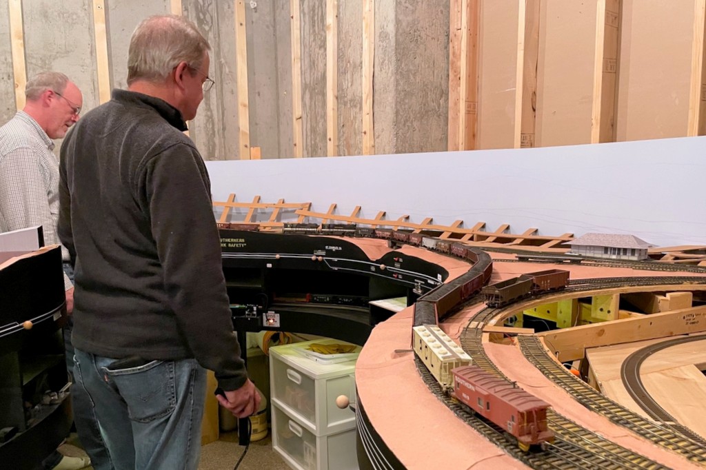
Having completed work at Baker, Patrick slows the mine run to a crawl on the way back to Mayflower as Stuart protects the crossing with fusees
Growling L&N C420 1317 plied the Southern’s rails without incident with Stuart at the throttle, but his luck was not to hold when he took the throttle for the St Charles Switcher with GP38AC 2877 and GP35 2649 at his control. Let’s just say that there is a certain switch at Mayflower that 2649 decided it needed to jump every time, and it only needed to cross that switch 18 times to work the tipple. Despite several breaks to ensure proper gauge and freedom of motion in 2649’s trucks and tweaking some spots in the switch with a gauge and pair of pliers, 2649 was determined to stay on the ground. Of course, now that the session is over, 2649 navigates that switch just fine… sigh. I still have a long way to go until things are bulletproof.
First use of the new “fusees” I’m installing at all the grade crossings
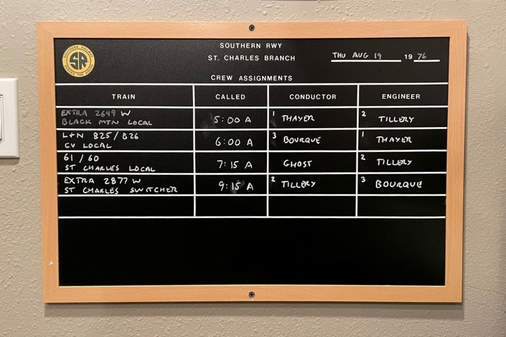
First use of the new-and-improved crew assignment board
First time a “tipple” has been in place at Baker (a new mock-up)
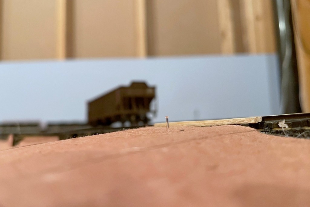
First use of a new “speed-retarding system” on the steep portions of the St Charles Yard (spaced-out monofilament line)
First use of the new “safety slogans”… and no one was seriously hurt 😉
And of course some areas for improvement and “lessons learned”:
Too many derailments–I still need to improve my trackwork to make it bulletproof
I need to make blocking instructions more prominent if I want them to be followed
I don’t think the use of the train-order semaphore in St Charles is as understandable as it needs to be
I still need to work on the crew assignments to better balance how much each operator works
The St Charles Switcher arrives back in St Charles completing the ops sessionCrew assignment board for the session–I modified it halfway through to give “operator 1” more jobs… still working on balancing things
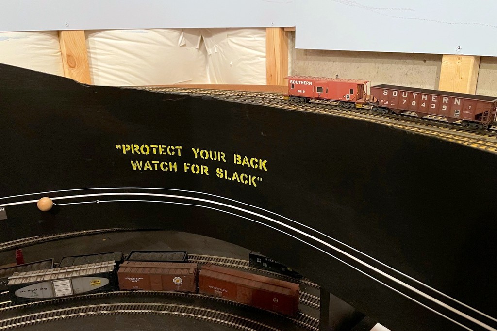
“Protect Your Back Watch for Slack” safety slogan in the yard at St. Charles
Real railroaders are inundated every day by safety slogans. This focus on safety appears to have ramped up in earnest in the 1970s with slogans appearing on all sorts of company publications, in shops, and on rolling stock like cabooses. I thought it would be fun to bring some of these prototypical safety reminders to the layout.
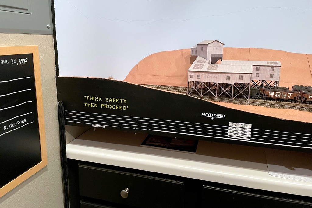
Safety slogan “Think Safety Then Proceed” occupying a corner at Mayflower
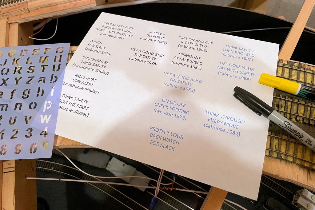
The first step was to determine what kind of safety slogans the Southern used. I found the best place to find them was just above the steps of a caboose, so I pored over hundreds of photos of Southern cabs, zooming in over the steps to see what slogans I could make out. I was able to capture more than a dozen slogans including the following:
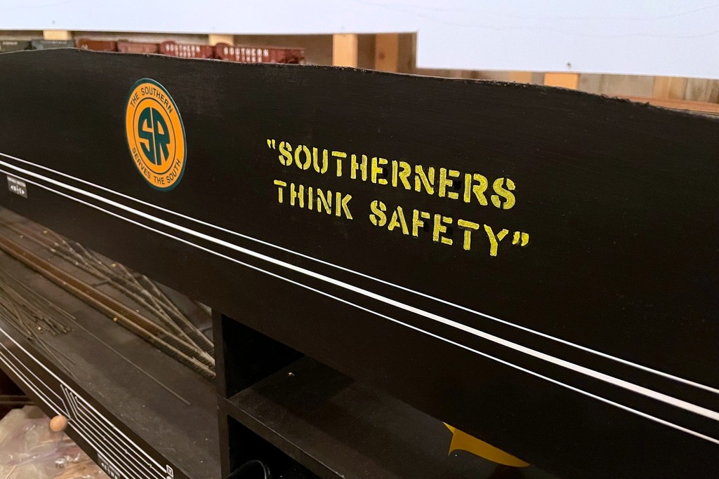
“SOUTHERNERS THINK SAFETY”
“WATCH FOR SLACK”
“GET A GOOD GRIP FOR SAFETY”
“GET ON AND OFF AT SAFE SPEED”
“ON OR OFF CHECK FOOTING”
“THINK SAFETY THEN PROCEED”
“LIFE GOES YOUR WAY WITH SAFETY”
“SAFETY – GO FOR IT”
“DISMOUNT AT SAFE SPEED”
“PROTECT YOUR BACK WATCH FOR SLACK”
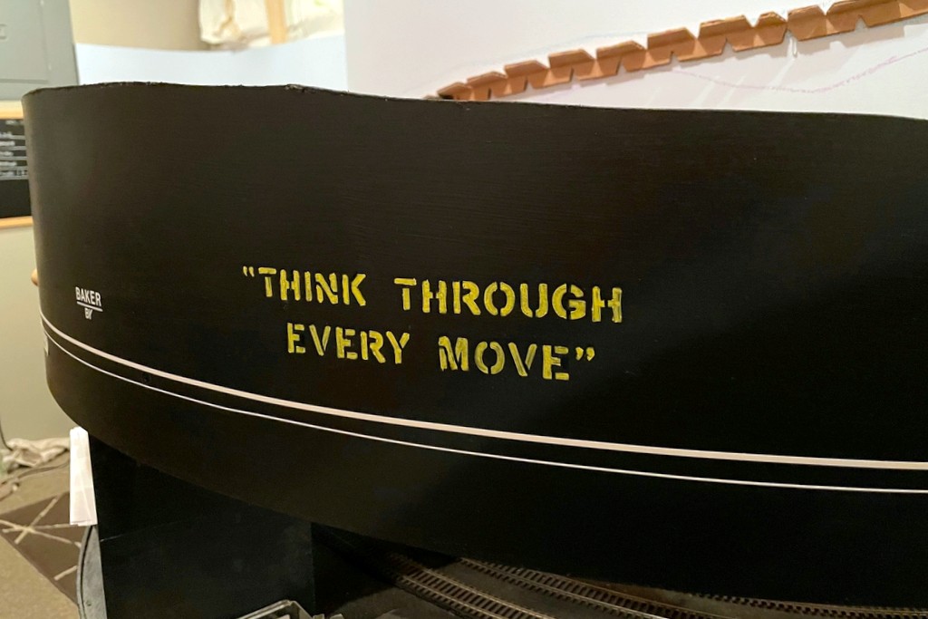
“THINK THROUGH EVERY MOVE”
“GET A GOOD HOLD ON SAFETY”
This safety slogan is the most unique to the Southern, so I placed it next to the Southern logo on the fascia
Armed with these slogans, I headed off to Hobby Lobby to pick up the closest lettering stencil I could find in the 3/4″ size range, a yellow paint marker, and a black paint marker – less than a $10 investment. I selected a few blank spots of fascia around the layout and used masking tape to provide a level reference line for the lettering. I just hand-held the stencil against the fascia, applied some yellow paint marker in the correct letter, and wiped the wet paint off the template. I carefully held a paper towel up to the freshly painted letter and dabbed it dry without smearing–this not only allowed me to move on to the next letter quickly, but it helped to created a worn and mottled look to the letters that I liked. Once the upper line was done, I measured and picked the middle point of the line, reset the masking tape for the lower line, and started with the middle letter for the lower line to keep things centered.
I decided to add the quotation marks as well. They appear on some of the slogans (not all), but I think it helps make it clear that these are pulled from somewhere instead of just being a random sign on the fascia. The template didn’t have the quote marks, so I used an X-Acto blade to make my own stencil in a blank spot on the plastic template. After things dried, I used a combination of the black paint marker and a sharpie to clean up around the edges. Finally, I used the Sharpie to draw in some extra stencil lines across the letters using pictures of actual Southern stenciling as a guide (for example, a line under the top part of the “T” and lines across the top and bottom of the “C” and “S”).
Ok, there’s one more project down that’s been rattling around in my brain and one less excuse to procrastinate on getting back to scenery…
This was a simple project that only required a list of slogans, a cheap lettering template, a paint pen and a Sharpie
This safety slogan is the most unique to the Southern, so I placed it next to the Southern logo on the fascia
Safety slogan “Think Safety Then Proceed” occupying a corner at Mayflower
This safety slogan seemed particularly appropriate for a switching-based layout
I put the “Protect Your Back Watch for Slack” slogan in the yard at St. Charles
The semaphore in action indicating the St Charles Local has no orders to pick up before proceeding eastward to AppalachiaBlade down and red light indicating both east and westbound trains must stop at the station to sign for orders
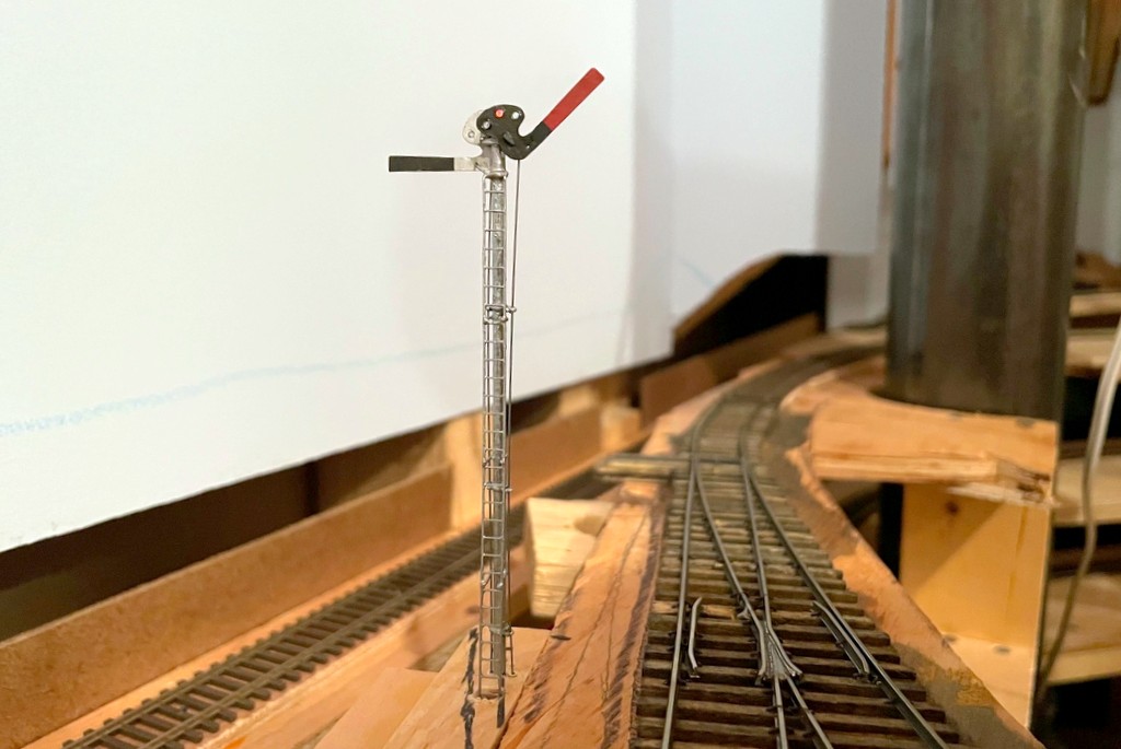
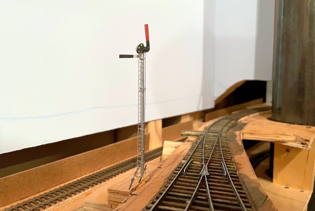
I had one major project to complete before completing the scenery base on the lower level, and that was the train order signal in St Charles. I’ve been putting this off for a couple of reasons. First, I’ve never made a full working semaphore before, so I wasn’t sure exactly what I was taking on–the dwarf semaphores I made a while ago gave me a significant head-start, but this was much more complex. Second, I don’t know exactly if the Southern used a semaphore in St Charles – or if they did where it was located – so I was hopeful my procrastination would result some evidence. Alas, I finally just had to bite the bullet and build the thing! Yes, I know there are commercially available semaphore kits, but what would be the fun in that? I’m a glutton for punishment, and I had a bunch of brass stuff laying around, so why not try to scratchbuild one?
I know with 100% certainty that the station in St. Charles had an operator who passed train orders to Southern and L&N crews working the branch. There is both photographic and timetable evidence for this. In the era I model, it was typical for a train order station to have a three-color signal of some sort indicating “red” (stop to sign for orders), “amber” (slow down to pick up orders) or “green” (no orders – proceed), and a three-position semaphore was common. On most stations, the semaphore is built right alongside the station’s office with the control levers inside the station. However, pictures of the St. Charles station clearly do NOT show an adjacent semaphore or any other type of signal. The only thing I can think is that the Baileys Creek Branch to Mayflower cut off the St. Charles main a couple hundred yards geographically south of the station, and train movements on this branch were controlled by the station–perhaps the signal was closer to this junction to allow train crews to see it an heed from both the St. Charles and Baileys Creek Branches. So, that’s what I chose to model!
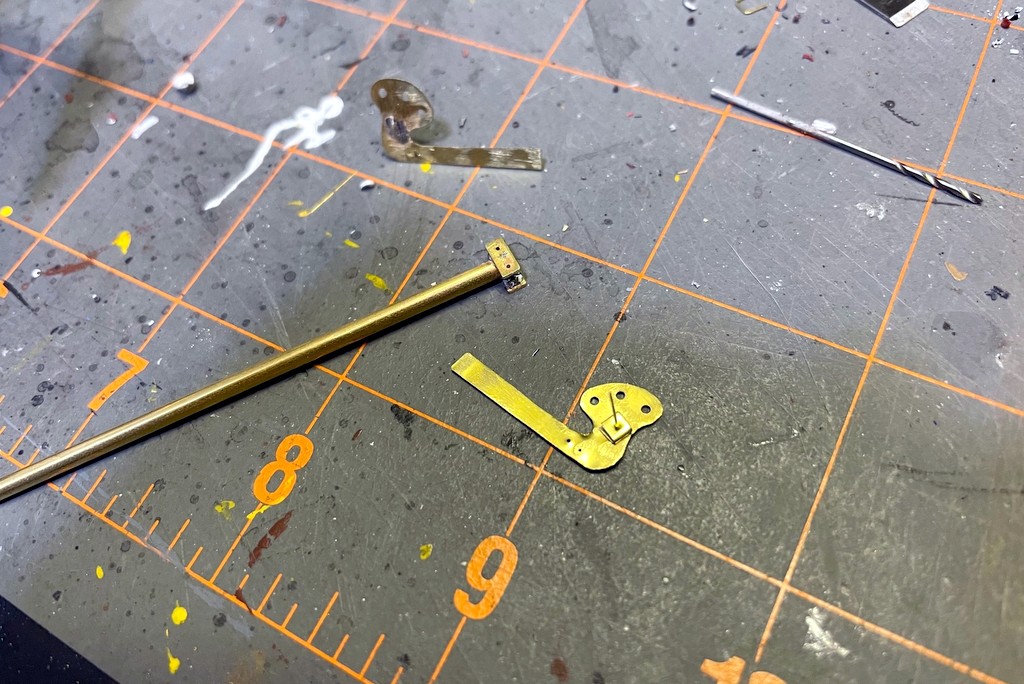
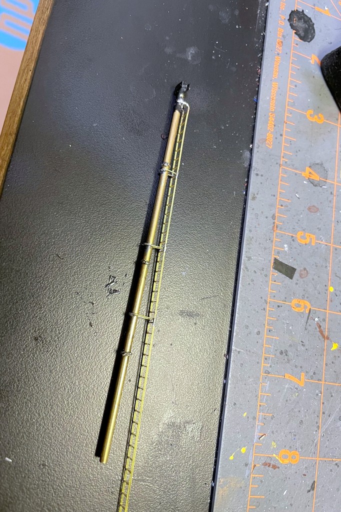
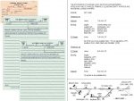
After finishing the semaphore blades, I attached a .015″ brass wire via solder and made a spacer from brass strip folded on itself. I used the same brass strip to make swivel bases for the blades on both sides of the pole
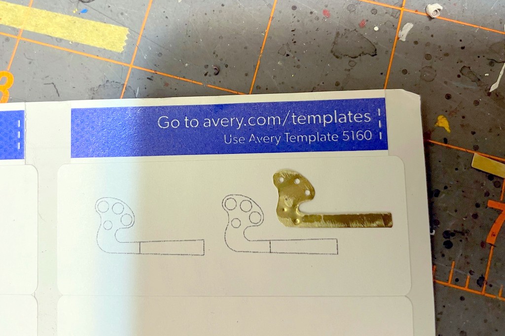
Like my dwarf semaphores controlling access to the coal branches, I wanted the semaphore to be fully operational including lights, blade movement, and fascia-mounted controls. The first job was making some semaphore blades. I did this by making an outline of an upper-quadrant blade in PowerPoint, scaling it to 1:87, and printing it onto a label. After attaching the label to some thin sheet brass, I drilled holes for the lenses, pivot point, and control rod and cut out the blade with scissors, using a file to clean things up. I soldered on the pivot rod, .015″ by bending one end, inserting it through the hole, and soldering it to the blade face. Next I added a small spacer for the blade onto the rod made from a piece of small brass bar bent on itself with a hole drilled through. I painted the blades flat black and insignia red for the blade end. The back of the blade got some silver Sharpie following pictures I’ve seen of other Southern stations. The lenses are just short pieces of fiber optic with one end melted into a round shape using a soldering iron (just hold it near the end of the fiber optic), attached with CA and colored with kids markers.
The next step was to add the brass ladder stock and connect it to the mast with U-shaped .015″ brass wire
The mast is a piece of 3/32″ brass tube. I made two mounting plates for the top out of brass bar, filed flat spots onto the tube, and attached them via solder. Next I added some guide loops for the rods that would go from the ground to the blade. I bent something resembling the shape of Saturn out of .015″ brass wire and soldered it tightly around the mast, using a semaphore mast diagram printed to scale as a guide for positioning, three guide loops total. This resulted in two U-shaped loops, one on either side of the mast. I finished the loops by soldering a small piece of wire across each U to make a smaller hole to the outside away from the mast. My soldering skills are not great, so this was a lot of ugly blobs until I took a file and cleaned things up. I added a piece of brass ladder stock by connecting it to the top with solder, bending it, and making U-shaped supports out of .015″ brass wire which I soldered into place in three locations and cleaned up. I painted the mast assembly flat black and then used a combination of silver Sharpie and silver paint to finish it.
Now I was ready to put the blades onto the mast. I fashioned some control rods from .015″ steel music wire, inserted them into the blade holes, and ran them down the guide loops on each side. After inserting the blade pivots into the mounting plate, I bent the brass rod 90 degrees to hold each blade in place while allowing it to pivot freely. I made the base from scraps of plywood (see pictures) and drilled a 3/32″ hole for the mast, two adjacent 1/16″ holes which I lined with 1/16″ brass tubing for the control rods, and a larger hole for the ladder to slide into. I press fit the mast into the holes with the rods going through their brass tubes. Then I ran a piece of fiber optic cable down the tube. I first tried to file one end of the fiber optic at an angle to get it to shine through the blade lenses, but this didn’t work well. I ended up holding the fiber optic over a spare piece of 3/32″ brass tube which I heated with a soldering iron. When the tube got hot, the fiber optic bent itself over the tube in a perfect curve which still conducted light well. A little more heat to make a rounded lens at the end, and I had my “light” for the blades.
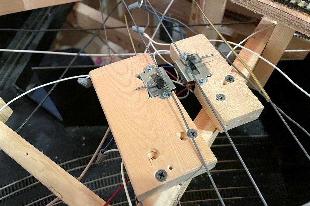
Here are the mechanisms made from 3-way slide switches. Not only do the switches route power to the bi-color LEDs, it also connects the lever to the signal mechanically and provides the detents for movement
I wanted to use .062″ steel music wire (the same stuff I use for manual turnout controls) for the fascia-mounted control rods, so I crafted two triangular levers out of thick styrene hinged at one corner to convert the horizontal control rod movement into vertical movement for the blade control rods. I covered this in some detail with the dwarf semaphores, so I won’t cover it again here. With the mechanism in place, I mounted the base and semaphore assembly in place on the layout. Next, I worked on the control rods made from 36″ pieces of .062″ steel music wire. Where they would cross through benchwork, I drilled 2/32″ holes and lined them with brass tubing. I was able to get a pretty good bend in the control rod without it kinking this way.
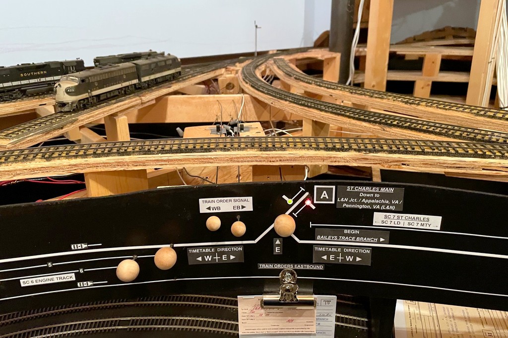
Here’s the finished semaphore from levers and lights to the blades in the background
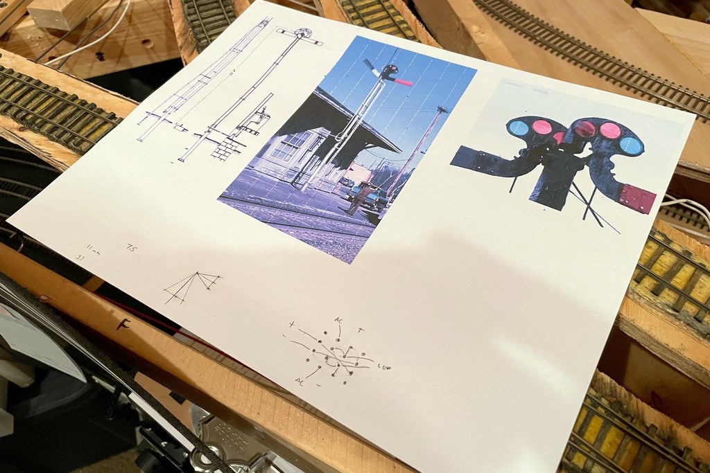
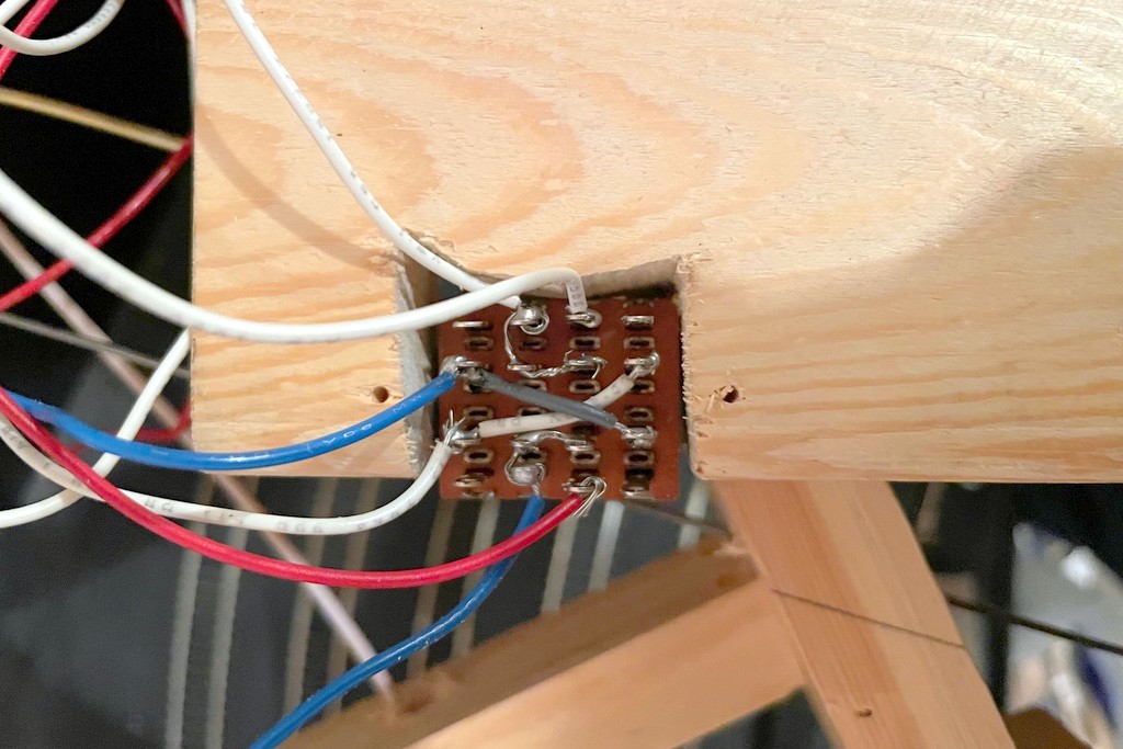
The heart of the control rod mechanism is a 3-way slide switch. I bought a handful of these for the dwarf semaphores because of their longer throw, but it turns out they were exactly what I needed to control both the throw and the lights for the full semaphore. I’m using 2-lead, bi-color red/green LEDs for the lights. Controlling the red and green is easy enough with DC and crossing the +/- leads on two of the poles on the switch to get the red and green on the end throws of the switch. For the amber, I wanted to use the AC current from my track power. It took a bit of thinking through the use of the 16 leads (it’s a 4-pole slide) to figure out how to route both AC and DC power to the same LED without ever crossing the streams, but the arrangement seen hand-drawn on my cheat sheet (see gallery below) works well. I secured the rods to the semaphore to the slide switch by bending them 90 degrees and inserting them into a hole drilled through the switch control. A second rod inserted through a second hole in the switch control was run through a piece of 3/32″ brass tubing to the front of the fascia where I capped it off with a wood ball (smaller than the ones I use for switch controls so operators can tell the difference).
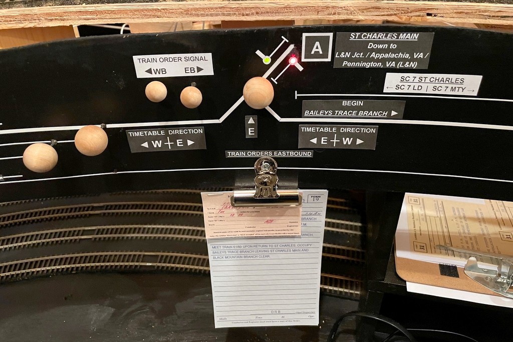
The final step was to run LEDs from both switch mechanisms to the fascia where I used stick-on letters and graphic tape to make a little drawing of a semaphore in each direction alongside the track diagram–the operators can look on the fascia to see the color indication if they don’t want to use (or don’t understand) the blade positions on the layout. Finally, I added a second clip to hold orders under the fascia so that the old clip is now “train orders westbound” and the new clip is “train orders eastbound.” So far I’m really happy with how the semaphore looks and now it operates, and it was really fun to build. I know it will add yet another aspect of prototypical operations to the layout as crews now have to read signals to see whether or not they need to pick up orders.
I made a diagram of a semaphore blade in Microsoft PowerPoint then printed it in HO scale onto a label. This made it easy to attach it to the sheet brass, drill holes, and cut it out with scissors
After finishing the semaphore blades, I attached a .015″ brass wire via solder and made a spacer from brass strip folded on itself. I used the same brass strip to make swivel bases for the blades on both sides of the pole
One of the finished blades painted black and red with no stripe per Southern custom. The lenses are short pieces of fiber optic with one end melted round by holding it close to a soldering iron. The color is just marker
I made guides for the blade control rods using .015″ brass wire bent into a “flat Saturn” shape around the mast. The control rod is .015″ steel music wire
The next step was to add the brass ladder stock and connect it to the mast with U-shaped .015″ brass wire
The base plate is simple. Under the signal is a second layer of plywood to get the signal to track level. Holes for the mast, rod guides and ladder are in the middle (the right-hand holes are mistakes). The plywood fin will support the levers to connect the manual control rods to the rods going up to the blades
Here’s where the lever rods meet the rods going up to the blades. The multiple holes in the styrene allow the rod to be repositioned for more or less throw (I ended up using the top hole on both to get more throw)
Blade down and red light indicating both east and westbound trains must stop at the station to sign for orders
Blade halfway and amber light indicating the eastbound train should slow to pick up orders (handed up by the operator) but doesn’t need to stop and sign for them
Blade up and green light indicating no orders for the eastbound train
Here’s the little cheat sheet I made up. I scaled the blueprint to HO and used the sheet to plot my throw and my wiring for the 3-way slide switch
This is the finished wiring of the 3-way slide switch. The ends connect to DC for the red and green colors of the bi-color LED. The middle attaches to AC (DCC track power) for the amber (rapidly flickering red and green)
Here are the mechanisms made from 3-way slide switches. Not only do the switches route power to the bi-color LEDs, it also connects the lever to the signal mechanically and provides the detents for movement
Here’s the fascia end of the semaphore including levers (WB in, EB out), indicator lights along the track diagram, and the clip for the orders which necessitate the signal
Here’s the finished semaphore from levers and lights to the blades in the background
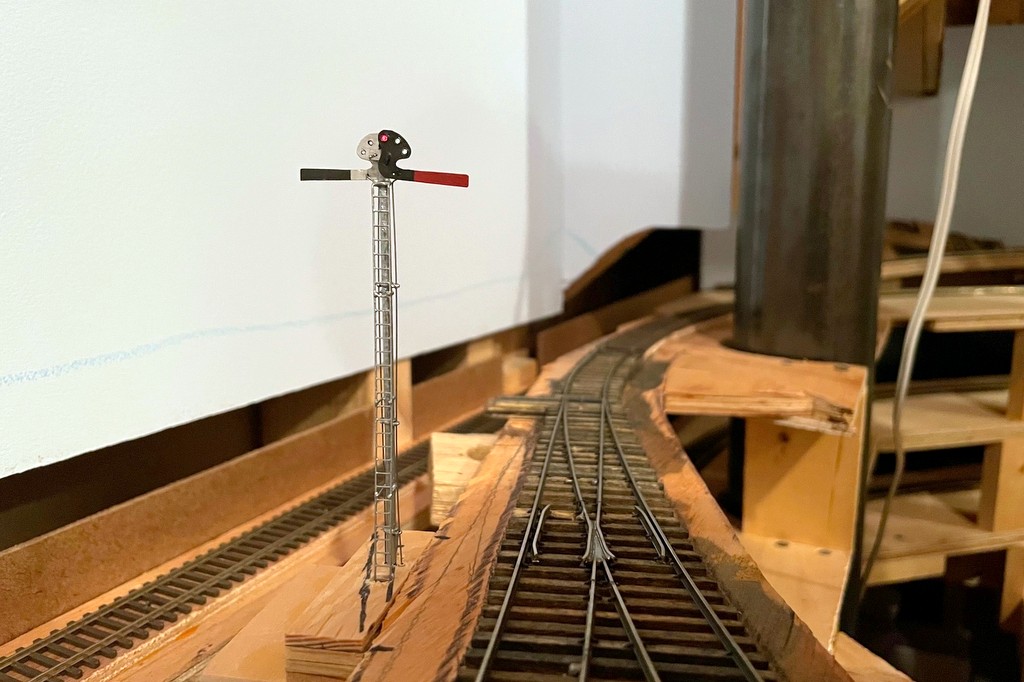
The semaphore in action indicating the St Charles Local has no orders to pick up before proceeding eastward to Appalachia
Patrick working the St Charles Local–dropping off fresh empties and picking up loads to take back to Appalachia and Andover
Yesterday was the second operating session on the St Charles Branch, and Patrick Tillery was again my partner in crime. Despite only having the tracks for one deck complete, we were able to run 4 trains, and it took us about 2 1/2 hours to get all the chores done. That’s a pretty good showing for only 1/2 the layout and 2 operators! I learned a lot in the session, mainly which switches to keep working on to avoid derailments, but at least we didn’t have any repeat offenders, so I’ll call it progress!
L&N 100 (still an “in progress” model) works Mayflower as the power for the CV Local
For this session, I picked the date July 30th, 1969 which meant F-units for the Southern’s mine run and and RS3 for the L&N. We ran a “busy day” with two Southern mine runs. Since the helix was recently completed, I staged the “Black Mountain Local” on the helix with loaded hoppers as if it was returning from the tipples which will eventually be on the upper deck, so it was more like 1/2 a train, but it did add a little more operation as the train needed to be blocked in the yard and the power tied up. It also required some “meets” in St Charles, so the orders needed to specify which legs of the wye to occupy and which to leave open for the higher priority trains. No collisions, so I guess I’ll call that a success.
In addition to having a full set of fascia controls to work with and the beginnings of backdrops, this session had some other notable “firsts”
First session with first gen diesel sounds (EMD 567s and and Alco 244)
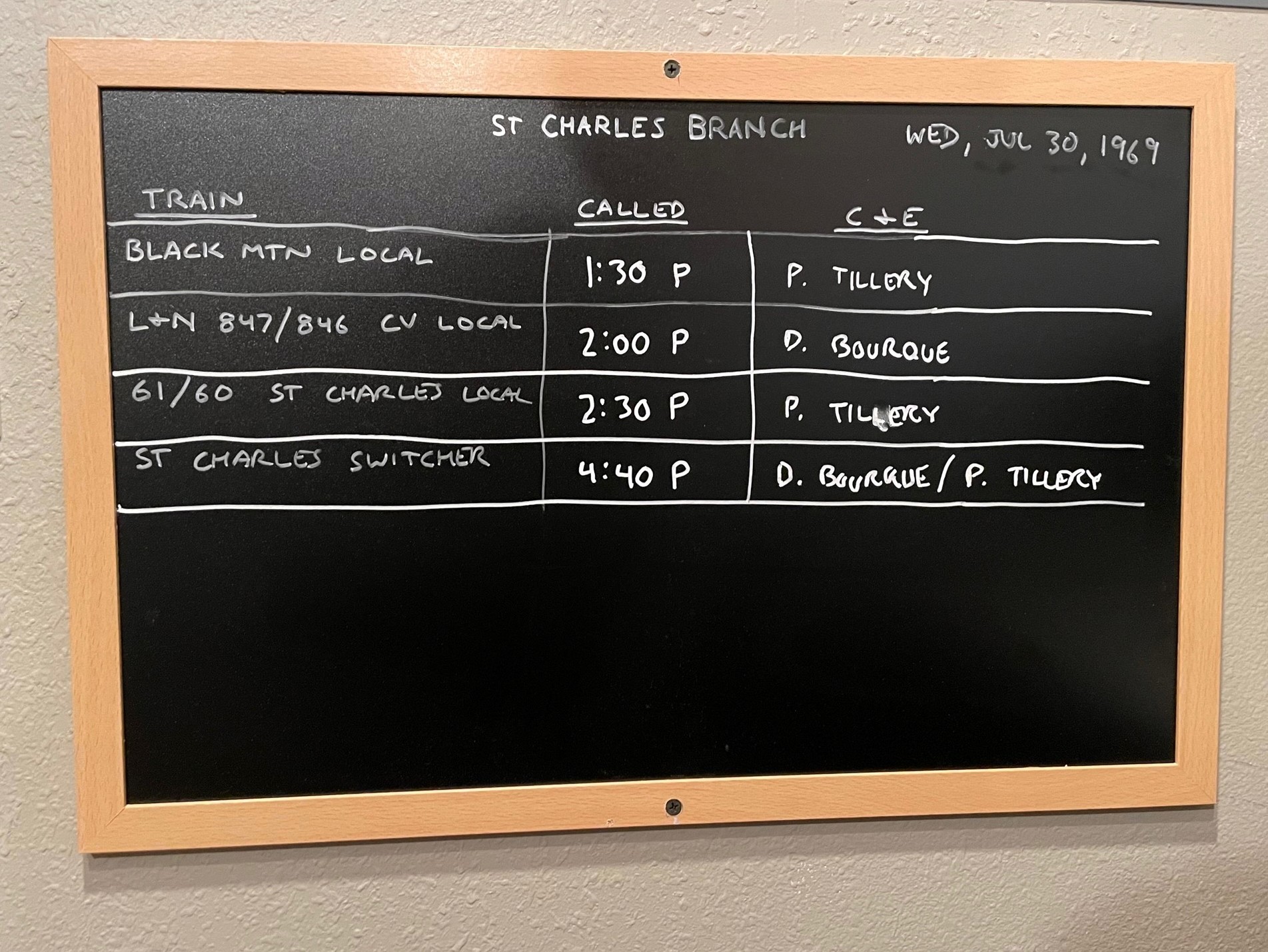
This is the makeshift job board for session #2 and the 4 trains we ran
Some things I learned:
Even with the switch lists, I probably still need a “master switch list” everyone can access
Instructions for the crews need to be a little more explicit on the job required and not just a blocking sheet
A little momentum in the locomotives made it more fun and realistic–I’ll probably turn it up a bit more next time
Even though it’s a small chore, using the switch locks and semaphore controls added some prototypical realism and slowed things down a little (which is good)
Overall I’d call it a success. It was fun, and it motivates me to keep going! If anyone reading this is ever in Colorado Springs, give me a shout and we’ll set up another.
This is the makeshift job board for session #2 and the 4 trains we ran
Since there’s no upper deck yet, the helix served as a staging track for the “Black Mountain Local”
Patrick finishing up the Black Mountain Local by blocking cars for pick-up by the St Charles Local
L&N 100 (still an “in progress” model) works Mayflower as the power for the CV Local
Patrick working the St Charles Local–dropping off fresh empties and picking up loads to take back to Appalachia and Andover
The Black Mountain Local stops to reset the dwarf semaphore now that their work is complete
Semaphores were a common way of signaling trains on the Southern Railway. Semaphores were often used at stations to indicate whether or not the train was cleared to proceed or needed to stop (or at least slow down) to pick up orders. Semaphores were also used to protect branches when trains were working on them, and these semaphores were usually set by the crews themselves. The St Charles Branch employed three such semaphores to protect the lines RR west of St Charles. Here’s the exact verbiage from the Employee Timetable:
“At points shown below, semaphore signals will govern the movement of trains and engines. When track is not occupied, signal will indicate proceed. When in either position, stop or proceed, signal will be fastened and locked with a switch lock. When indicating stop, position will not be changed until train or engine occupying the track clears it and the crew of same restores signal to proceed indication. West of St. Charles—located at the junction between Bailey Trace and Fawns Branch lines.”
I definitely wanted to model this aspect of operations, and as a bonus, two of the locations of these semaphores correspond with long sections of hidden track on my layout, the hidden track between St Charles and Mayflower on the Bailey’s Trace Branch, and the helix between St Charles and Turner’s Siding on the Black Mountain Main. These would not only serve the purpose of adding more prototypical operations, but they would also serve a very practical function of protecting trains that can’t be seen without a dispatcher.
I learned from a former Southern employee who worked in this area that these were “dwarf semaphores.” I haven’t been able to find a picture of one of these exact devices near St Charles, so I Googled “dwarf semaphore” to see what they were all about. They operate just like the tall semaphores and come in both upper- and lower-quadrant designs, and most have lights. They only sit about 3-4 feet tall, though, and have a blade somewhere around 14″ long–that’s super tiny in HO scale! I picked a Union Switch and Signal upper-quadrant, two-light design. I didn’t see anything resembling this available in HO scale, so I set about building my own operating version from sheet brass and wire.
Faceplate and blade made from brass with the swivel wire soldered in place
I made a drawing of the blade and faceplate with the lights, sized it down to HO scale, and printed it on sticker paper. After sticking it to a sheet of .005″ brass, I was able to drill holes for the lights, swivel and actuating arm and then cut it out with scissors. After cleaning it up with a file, I bent a piece of .015″ brass wire, inserted it through the swivel hole, and soldered it to the faceplate. I drilled a hole for the wire through a piece of 1/16″ brass tubing for the base. I wanted to use fiber optics for the lights, so I soldered a 1/16″ long piece of tube to the tall tube angling up to where the light would be to hold the fiber optic strand. I painted the faceplate and tubing black, then made lenses by melting the end of a piece of fiber optic into a mushroom shape holding it near a soldering iron. A little red for the blade and a white sticker stripe and the faceplate was complete.
Completed dwarf semaphore model and lever mechanism
I mounted the base post in a piece of plywood and drilled a hole for a second piece of 1/16″ brass tube underneath the blade for the actuator arm. After inserting the faceplate and securing it with a bend on the back side of the tube, I had a faceplate that swiveled freely. A piece of .012″ steel music wire bent at a 90 degree angle at the end was inserted into the blade and the tube for the actuating arm. On the bottom, I made a lever for the actuator that raised the actuator just slightly while allowing for significant travel for the longer actuating rod connected to the fascia. I filed the end of a fiber optic strand so it would be parallel to the faceplate and inserted it into the little brass holder and through a hole in the base. A little silver paint for the post, and the tiny dwarf semaphore was complete!
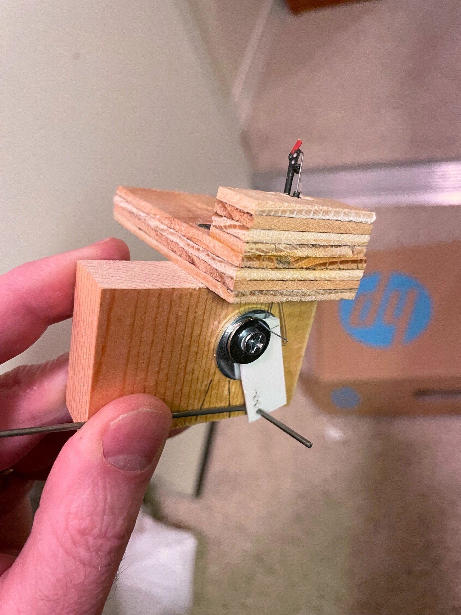
One of the things I wanted to model was the use of switch locks. I found some Miniature Locks on Amazon that suit this purpose perfectly! I decided to use a slide-switch mechanism like I use for all my switch controls, but I needed a longer slide to enable the lock to go in front of and behind the control knob to “lock” it into either position. I found some old three-position slide switches on eBay that did the trick! The slide switch serves two purposes–it “snaps” into position to hold the control and semaphore securely in position, and it allows for the routing of power to LEDs, in this case some bi-color red and green LEDs that change color when the polarity is reversed, something easy to do with a slide switch. After mounting the switch to the layout using a piece of 1×4″ board, I drilled two holes in the slide handle and used .o62″ steel wire to connect the slide to the lever under the semaphore and a separate rod through the fascia for the control knob, a 1/2 ball piece of wood.
Semaphore control in the “stop” position showing the red fascia indicator and lock
For the lock mechanism, I used a bar of 1/4″ x 1/2″ basswood with a hole drilled for the lock and inserted it through a hole in the fascia and benchwork adjacent to and just touching the control knob. The hole sits just ahead of the control knob when it’s pressed in and just behind it when pulled out. I also connected two LEDs to the slide switch and a 12V DC power supply. One LED is mounted behind and just through the fascia to serve as an easy indicator for the full-size operators. The second was inserted into a hole drilled in the semaphore base where it can shine into the fiber optic strand.
The result is a semaphore with working lights, blade and a switch lock. While the dwarf semaphore sits about 3′ from the aisle and is tough to see, it is pretty cool to have an operating model and a tiny little red or green glow that matches the indicator on the fascia. Now the operators on the St Charles Branch, just like their real-world counterparts, have to stop at the semaphore, unlock the lever, change the indication, and re-lock the lever before proceeding up the branch (and do the reverse on the way back). While I’m not sadistic enough to make operators lock and unlock every switch they need to throw, working with switch locks a couple times during a session is one more step toward replicating the actions required on the real thing, and it adds a little prototypical time to the work required. Oh, and it helps protect trains without a dispatcher which is pretty useful.
[Note: since I first published this post, I decided to reverse my control mechanism so “proceed” is pulled out and “stop” is pushed in. It just required me to reverse the lever used to lift the arm. I figured having the crew move the lock to the front of the pull knob where it’s more obvious makes more sense.]
My PowerPoint drawings of semaphore blades and their HO scale counterparts
Faceplate and blade made from brass with the swivel wire soldered in place
Close-up of the mostly complete dwarf semaphore made from brass and fiber optics
Completed dwarf semaphore model and lever mechanism
The three-way slide switch wired up–the short leads are for the LEDs, the long leads connect to 12V DC
The internal guts of the control mechanism showing the two control rods routed through the handle of a slide switch
Two holes in the fascia, one for the control rod and one for the locking bar
Finished dwarf semaphore in the “stop” position–note the red light
The Black Mountain Local stops to reset the dwarf semaphore now that their work is complete
HO scale dwarf semaphore in the “stop” position
HO scale dwarf semaphore in the “proceed” position
Semaphore control in the “proceed” position showing the green fascia indicator and lock
Semaphore control in the “proceed” position showing the green fascia indicator and lock
Semaphore control in the “stop” position showing the red fascia indicator and lock
Semaphore control in the “stop” position showing the red fascia indicator and lock
Today I upped the operations realism a couple notches on the St Charles Branch by adding fast clocks!… Ok, with only half the tracks built and with only one partial operating session under my belt, it doesn’t take much to up operations several notches at this point, but the fast clocks are still really cool! While fast clocks are an important part of operating layouts, I was surprised at just how few good options are out there, especially for analog fast clocks. There are digital options available that work with your DCC system (nice feature), but modeling the ’60s and ’70s, I felt a digital clock display would be too gross an anachronism, and I’m working hard to transport operators back in time when they’re on the layout. I even played around with creating my own “analog” fast clock using MS PowerPoint which actually turned out pretty good for what it is–it works, but it was never intended to be a permanent solution. Feel free to download the “Poor Man’s Model Railroad Analog Fast Clock” (below) and play around with it–it will function somewhat online, but it works much better if you download it. You can read more about it and download a digital version as well here.
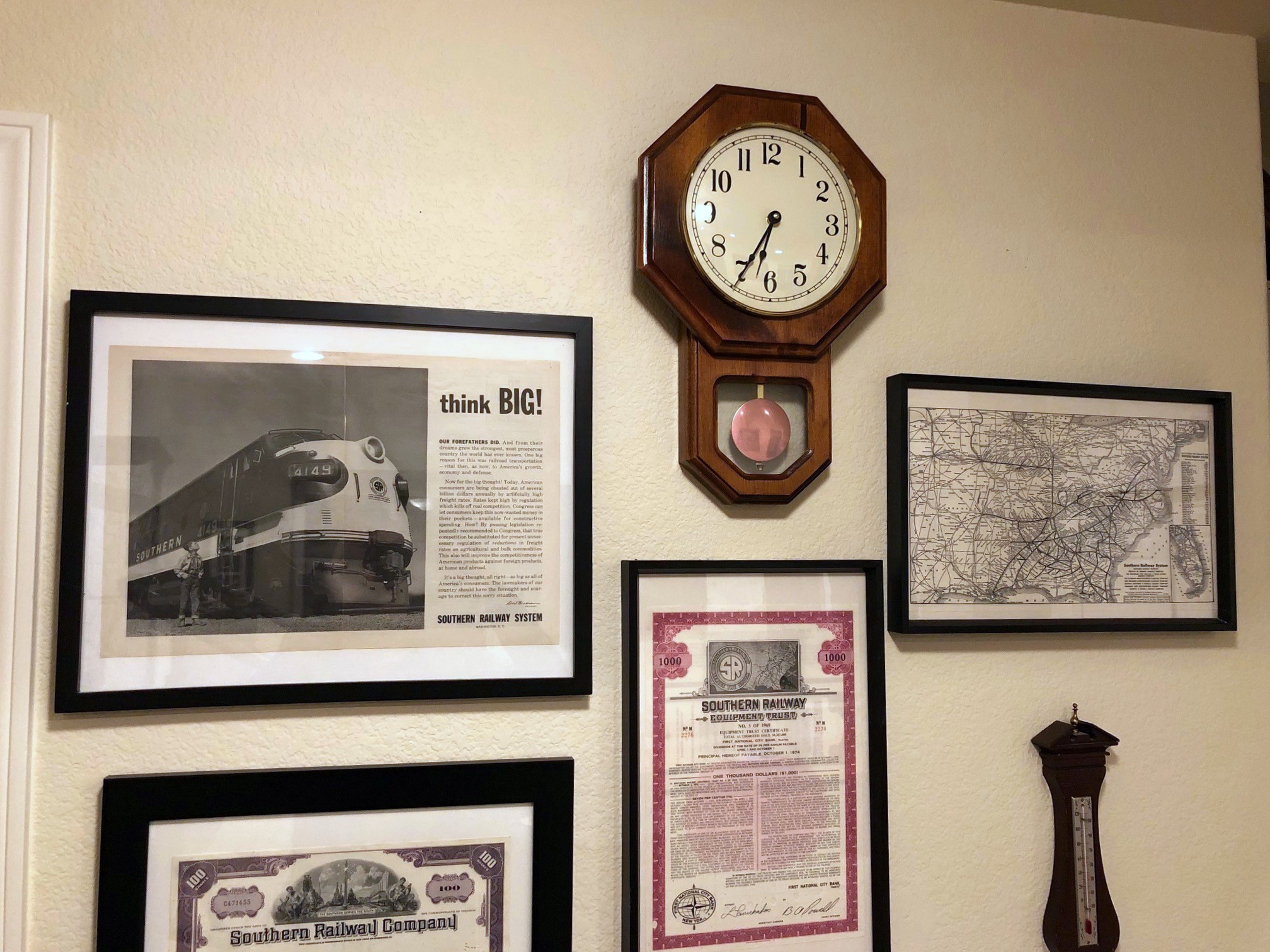
Regulator-style fast clock in the crew lounge. The FCC4 system let me retrofit this hand-made clock.
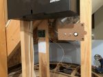
For the real solution, I needed a way to have multiple physical analog clocks all synchronized with an adjustable fast-clock ratio. I narrowed it down to two systems. The first was a WiFi system that offered both digital and analog clocks, but it was limited to a single style of analog clock, and I don’t really need MORE radio frequency waves in my house. In the end, I opted for Mike Dodd’s FCC4 fast-clock system. The FCC4 consists of a control board, three simple switches (run/stop, advance, and reset), and as many clocks as you need running off a two-wire bus. What intrigued me most was how Mike implemented the analog clocks–YOU buy the clocks, and he supplies the replacement mechanisms that will fit in just about any wall clock you can buy today. That feature enabled me to buy a clock for the layout room that had the style I wanted, AND it allowed me to convert a “Regulator” style clock made by my wife’s grandfather into a fast clock for the crew room (i.e., the rec room adjacent to the layout).
My temporary fast-clock control panel (the FCC4 is mounted in the background)
You can save some money by buying the kit version and assembling it yourself, but I decided to buy the assembled and tested versions of the controller and clock mechanisms, and everything worked like a charm (so refreshing in this day and age). I just needed to swap out the two clock mechanisms (a fun 30-minute project), add a few switches, and run several wires. Installation of the wires through the walls was the most difficult part of the project, but even that was pretty straightforward. In the end, I now have two fast clocks set to a 4:1 ratio that I can turn on and off, advance at a 17:1 ratio if needed, and reset to my session’s start time (5:30 AM for now) easily, and if I ever expand the layout into the spare bedroom next door, I just need to run a couple more wires and buy another mechanism to have another clock. I mounted the control board on a stud inside my helix space where it will be hidden from sight but easily accessible via a short crawl for troubleshooting or adjusting the ratio. The controls are on a temporary board for now–I’ll eventually install them in a recessed portion of the upper-level fascia to keep the switches away from little hands and wayward elbows.
If you need an analog fast-clock system, I would definitely check out the FCC4! Not only is Mike Dodd very responsive to questions, but he’s also a model railroader himself, so he’s designed this system from the perspective of an operations-oriented layout owner. I’m looking forward to my first operating session using the clocks where the times on train orders are more than just numbers on a piece of paper!
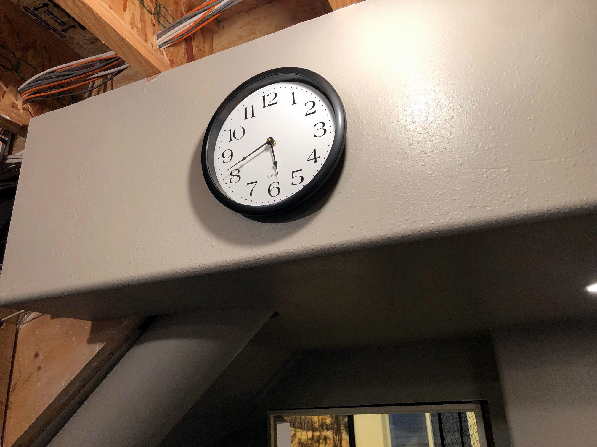
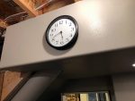
Fast Clock in the Layout Room
My temporary fast-clock control panel (the FCC4 is mounted in the background)
Regulator-style fast clock in the crew lounge. The FCC4 system let me retrofit this hand-made clock.
Operations, in my own words, is simply the means by which a railroad – or a layout – moves things to the intended location while keeping trains from colliding over a shared set of rails. Paperwork is an important part of railroading operations, so it stands to reason that paperwork should also be an important part of any operations-oriented layout. No one REALLY loves paperwork, though, so how much is enough? There are as many answers to this question as there are operating layouts, but I’ll share what I’ve settled on because I believe it strikes a pretty reasonable balance and works well for a sleepy coal branch layout like mine.
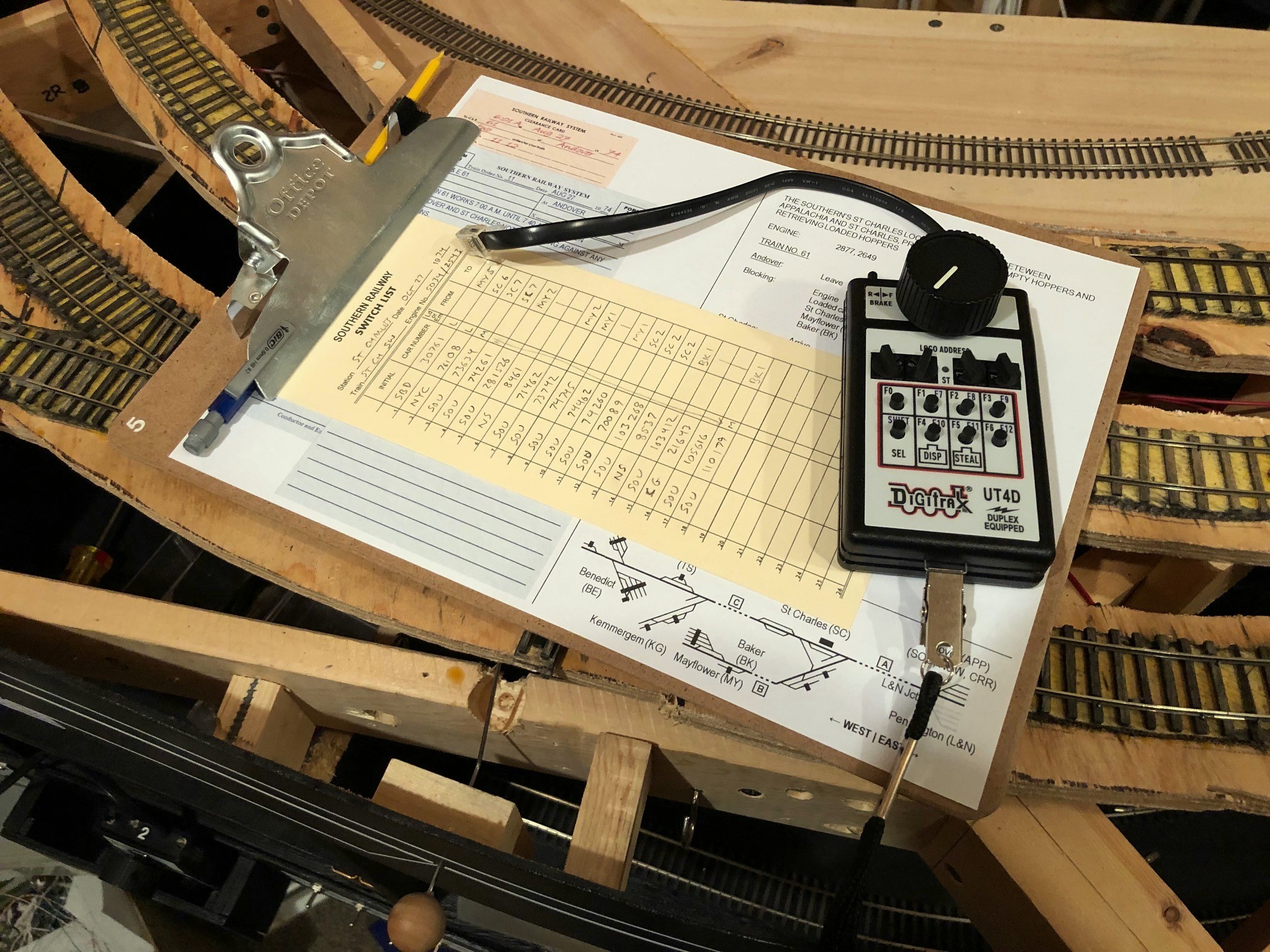
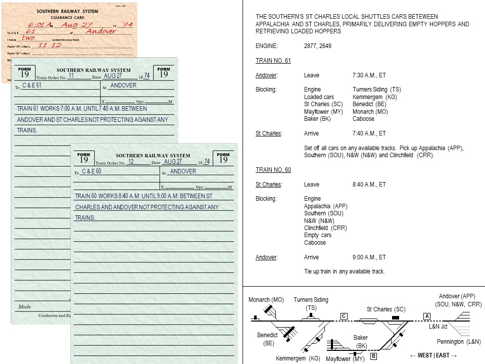
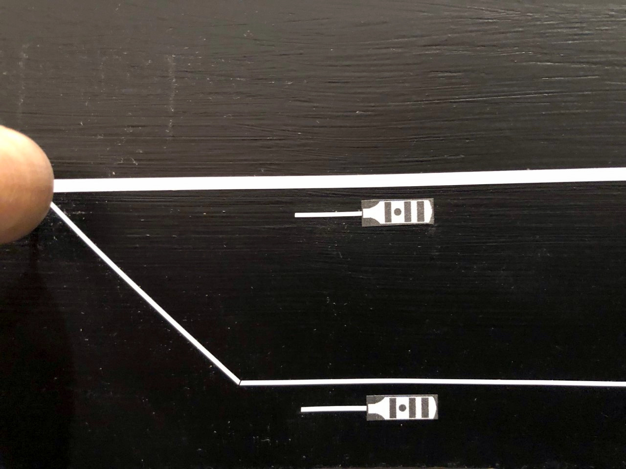
Everything the St Charles Local needs to operate on the layout
My goals for the layout’s operations:
Replicate essential elements of the prototype’s operation
Make paperwork realistic without being overwhelming (and avoid tedious paperwork that serves no modelable purpose)
Make it easy for operators to work their trains like the prototype and get the cars to the right place with minimal training
Avoid creating any boring jobs on the layout (a dispatcher would be a boring job on this layout and thus would always fall to the host)
No car cards (I realize I’m tipping some sacred cows here…)
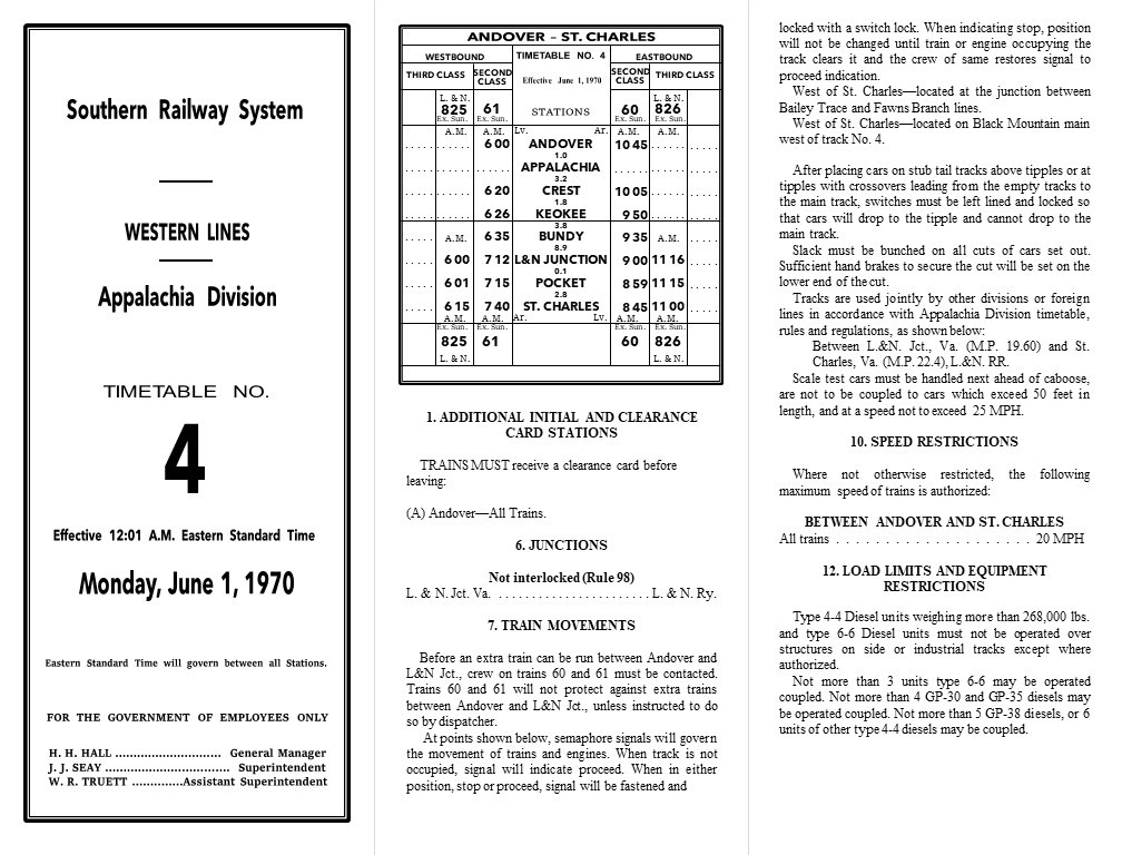
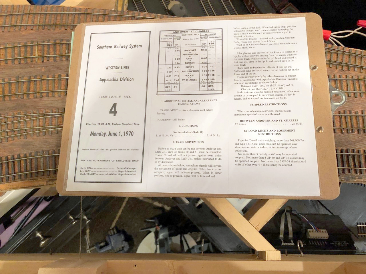
The first step was to understand operations on the prototype St Charles Branch. To help, I had photo captions, excerpts from articles, and some notes from individuals who worked in the area, but the real score was an Employee Timetable (ETT) of the Southern’s Appalachia Division circa 1970. Employee timetables are a critical piece of paperwork on the prototype. They list the scheduled trains for each line, the “class” of each train, the stations they run through, and their scheduled arrival times for each station. In a timetable and train order operations scheme, lower class or unscheduled trains (extras) must keep clear of higher priority trains in the timetable. While the timetable sets the basic scheme of operations, the dispatcher uses train orders for each crew to handle the details, telling them where and when they can work, what trains they need to meet and where, etc.
The Southern’s Appalachia Division dispatcher controlled far more than just the St Charles Branch, so a dedicated dispatcher for my railroad that employs 2-3 operators per session and no more than 2 trains simultaneously would be overkill. In the name of “avoid creating any boring jobs,” I wanted to see if I could completely simulate the role of the dispatcher in keeping the trains moving and separated without actually having a human playing the dispatcher on the layout.
Part 1. Moving the Trains
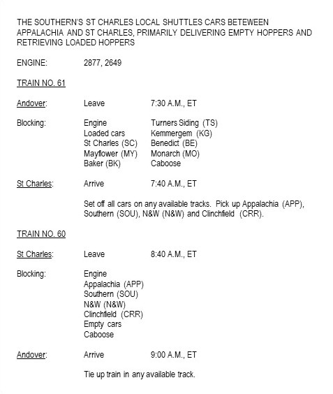
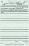
Employee Timetable
The Appalachia Division timetable listed one Southern second-class train each direction from Andover (the main coal-field yard near Appalachia, VA after 1965) to St Charles daily except Sunday (same crew with a different number for the outbound and return trips) along with one third-class L&N train each direction from L&N Junction to St Charles. All other trains, including the “St Charles Switcher”/”Black Mountain Local” mine runs out of St Charles would run as extras and have to steer clear of the scheduled trains.
Additionally, timetables list all the unique rules and procedures for that division including things like speed limits (20 MPH for the whole St Charles Branch) and instructions for working specific sections of track. One of the interesting sections in the Appalachia Division ETT reads as follows:
“At points shown below, semaphore signals will govern the movement of trains and engines. When track is not occupied, signal will indicate proceed. When in either position, stop or proceed, signal will be fastened and locked with a switch lock. When indicating stop, position will not be changed until train or engine occupying the track clears it and the crew of same restores signal to proceed indication.
West of St. Charles—located at the junction between Straight Creek and Gin Creek branches.
West of St. Charles—located at the junction between Bailey Trace and Fawns Branch lines.
West of St. Charles—located on Black Mountain main near east end track No. 5.”
I had heard about one of these semaphores from a former Southern employee who once worked in the area, but now I knew exactly where they were located and how they were used. This was perfect for my layout because I could use two of the three semaphores to protect long sections of hidden track (e.g., the helix between St Charles and Turners Siding), and best of all, the crews do the work to protect themselves on these lines without the need for a dispatcher or hard-to-model procedures like a fusee or flag.
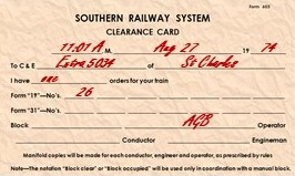
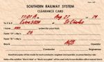
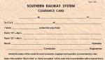
Clearance card showing how many orders the crew has
Even with these semaphores, trains still used orders giving them clearance to run. Train orders give crews instructions and authorization to occupy certain sections of track and to meet other trains. The dispatcher issues the orders to the conductor and engineer of each train, and the orders can be given over the radio or passed along to the crew by an operator at a station along the way (this was the primary use of semaphores at Southern stations–to tell a crew if they could proceed or needed to slow or stop or pick up orders). I’m no expert on orders, but the two common orders on most railroads are the Form 19 and the Form 31, similar forms in content, but crews needed to stop and sign a Form 31 while a Form 19 could be issued “on the fly.” The Southern seemed fond of the Form 19 while the L&N seemed to use more Form 31s, so I decided to use both. With no dispatcher, I also decided crews would start their jobs by receiving orders telling them their clearances and any other special authorizations or provisions. The practice of picking up orders before moving the train is prototypical, but of course, the train orders were not enough paperwork for the crews by themselves, so the Southern (along with other railroads) required all crews to have a “clearance card” before departing. The clearance card tells the crews how many orders they have and the order numbers for accountability–paperwork, after all, is all about authority and accountability.
So, to get trains working when desired and to keep them from colliding, I would need a timetable, clearance card, train orders, and a couple of semaphores. The actual Appalachia Division Timetable is more than 20 pages long, but I really only needed the sections that 1) apply to the St Charles Branch, and 2) apply to model operations. I’ve created a very condensed, single sheet version of the Appalachia Division ETT which has a cover (having it LOOK like a timetable is important to me), a simplified recreation of the timetable for Andover-St Charles, and instructions such as speed limits, use of semaphores, etc. that would be relevant to a model operator. I used the exact verbiage from the Southern timetable in most places, so it has the “feel” and function of the real thing without requiring an operator to read a 20-page document before running their train. To give it even more authentic feel, I took the time to match the the fonts and formatting as close as possible to the real thing–this took a long time, but I feel it’s well worth the effort. While Microsoft Word or Publisher may seem like the best programs to use, I find it’s far easier to build complex documents in Microsoft PowerPoint where I can control text boxes and shapes better. By taking the time to match the feel of the prototype ETT, the layout’s timetable becomes more than just a source of essential information on schedules and rules; it’s one of many parts designed to transport an operator into the layout’s time, place and purpose. It reminds them they’re working on a piece of the Southern Railway, that their operation is part of a larger “Appalachia Division,” that they’re running a part of a transportation system and not a toy, and their train’s purpose extends beyond the modeled portion of the layout.
My one-page recreation of an Employee Timetable for the St Charles Branch
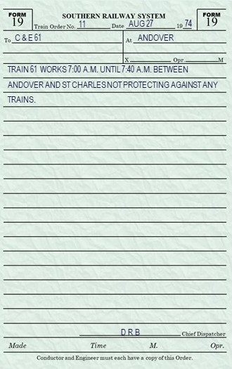
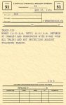
Train Orders
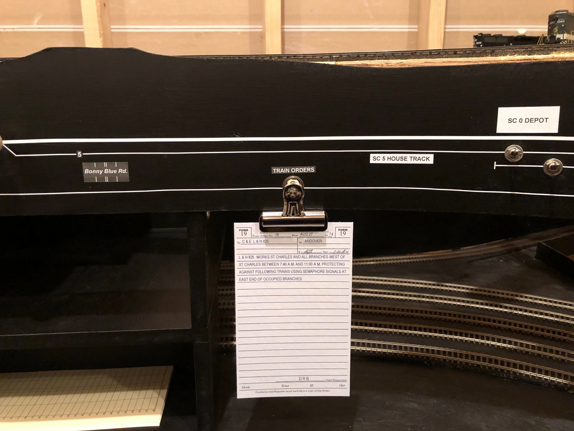
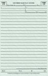
An example of my model Southern Form 19 train order
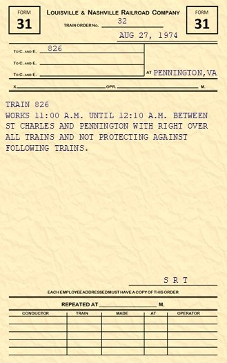
With the timetable in-hand, I now turned to train orders. Because there are very few trains running simultaneously on the St Charles branch, a single set of train orders would likely be sufficient for each train, and because all trains start at a “station” which, in reality, had an operator who could hand orders to the crew, it would be realistic to hand the orders to the crew when picking up the train. To create the train orders, I found images of actual train orders from my era online to use as examples for both the Southern and L&N. Train orders were often given in very simple and standardized language–easy to recreate and easy for a model operator (i.e., non-railroader) to understand. The Southern’s Form 19s were hand-written or printed in bluish ink on semi-transparent green paper, so I use a little color and underlying texture for my rectangle shapes to get this look out of a printer. I found some examples of Southern clearance cards and the L&N Form 31s in a book as well. Like the timetable, I took the time to recreate the Southern and L&N forms as painstakingly as I could in MS PowerPoint. The orders should remind crews they’re working for two different railroads, each with a distinctive culture and personality.
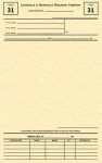
An example of my model L&N Form 31 train order
As far as what goes on the train orders, I try to keep it simple. The timetable mostly keeps the trains separated, so the most common verbiage is the train’s clearance between points on the railroad and the timeframe that clearance is valid. For inferior trains like the L&N’s CV Local (825/826), I’ll add extra verbiage like a reminder to expect to meet a superior train in St Charles and a reminder to use the semaphores for protection while on the western branch lines. I fully expect this verbiage to be refined as 1) I learn more about the prototype and actual orders used, and 2) I have more operating sessions and see what information the crews actually need to be successful at working and keeping their trains separated.
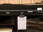
The scheduled trains on the St Charles Branch are “out and backs” which means they have a single crew and set of locomotives, but they’re technically two trains, one in each direction. This means most crews will have at least two train orders. The L&N crews receive clearance from the L&N dispatcher initially and run according to timetable on the Southern as far as St Charles. From there, they need to pick up a Southern train order to proceed railroad-west past St Charles and work the branches. I’m currently using a clip on the fascia near where the St Charles depot will go with orders to be picked up, and I’ll eventually have a semaphore at the depot I can set to tell the crews to stop.
A train order awaiting pick-up at St Charles
So far I’ve got a way to keep the trains moving and separated without a dispatcher–time to move on to getting the cars to the right locations.
Part 2. Moving the Cars
There are many ways to move cars on a model railroad including tabs on cars, car cards with waybills, and switch lists. The benefit of tabs on cars is the tab (like a waybill tacked to the car) follows the car and doesn’t create a need to carry a lot of extra paper. It also doesn’t need unique car numbers, something important with model runs of single car numbers a couple decades ago. However, for me, tabs on cars is not an option because I don’t want non-prototypical things cluttering up my models and breaking the illusion of reality more than the models are already doing, and all my cars will have unique numbers anyway. Car cards with waybills do a great job of moving a car’s destination from location to location using the prototypical practice of a “waybill” and providing additional details about a car’s lading. On the downside, they require some training (like when to flip a waybill), they require extra space on the layout/fascia at each town, and they require operators to carry a bunch of cards along with their train–I’ve been at operating sessions where cards went flying, went missing, or got separated from their car leading to messes, “mystery cars” and operator confusion. Additionally, the movement cycles of a coal hopper are very simple, and the lading and load/empty status are self-evident taking away two benefits of car cards.
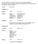
Switch Lists
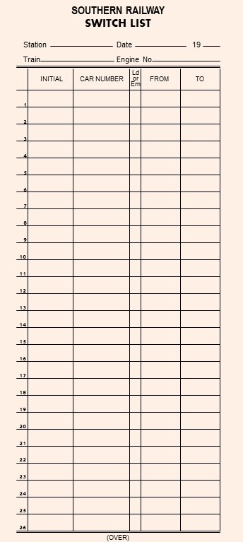
Recreated Southern switch list for my layout
That left me with switch lists. Switch lists are used on the prototype, either hand written or computer generated. They’re used mainly on local trains that will be setting off and picking up cars (not really needed for a train that’s not doing any switching). The switch list is specific to a train and tells the crew where each car in their train needs to go using the car’s initials (e.g., “SOU” and “LN”), car number, and some sort of destination designator. They often have additional information such as the car’s tonnage and load/empty status. The switch list is built by the conductor FROM any waybills or other routing information the conductor may have, so a crew doesn’t really need the individual waybills if they have a switch list.
On my last layout, I created a master list of every car on the layout and its destination (call it a “master switch list”), and I provided crews with blank switch lists they could use to build a tailored list for their train, much like a real conductor would do. However, I soon found that only the most die hard members of the crew would take the time to build their own list. For now, I’m building the switch lists for my crews and making it part of their starting paperwork along with the timetable and train order. I use the front side of the switch list for the outbound cars and the backside of the switch list for inbound cars, so crews merely have to flip it over instead of building it. I may revert to having crews build their own (or at least portions of it) in the future, but for now, I view the USE of a switch list as essential paperwork but the BUILDING of a switch list as tedium which I’m willing to endure but not push onto my operators.
To create the switch lists, I built forms in my favorite graphics program (yup, Microsoft PowerPoint) that I print out 3-per-page, front-and-back on thick tan paper and cut out. I found pictures of both Southern and L&N switch lists online (eBay is a great source for pics of old documents like this) and created railroad-specific switch lists for crews (L&N version below).
Destination Codes
A key part of a switch list (and a waybill) is understanding the destination of the car. This can be done in many ways as long as each destination is unambiguous. Because a train usually performs switching within a town/station area, trains are typically “blocked” to group cars for each town/station–this makes it very helpful to include the town/station in the destination for each car. Once the car gets put on the correct train and taken to the correct town, it needs some sort of unique industry identifier, and for industries with more than one track, a unique track identifier. While you can use long-hand like “Mayflower / Mayflower Tipple / Empty track #3” as a destination, it gets a little tedious to write out, so like many other modelers, I use short-hand 2-letter codes for each town and a unique number for every track in the town. Here are my town codes for on-layout destinations:
SC – St Charles
BK – Baker
MY – Mayflower
TS – Turners Siding
KG – Kemmergem
MO – Monarch
BE – Benedict
I picked letters that not only make sense for the town name but are also hard to confuse with anything. For example, both “Mayflower” and “Monarch” codes start with an “M,” so I chose a second letter that would be hard to confuse with the other name (i.e., “Y” is found only in Mayflower and “O” only makes sense for Monarch).
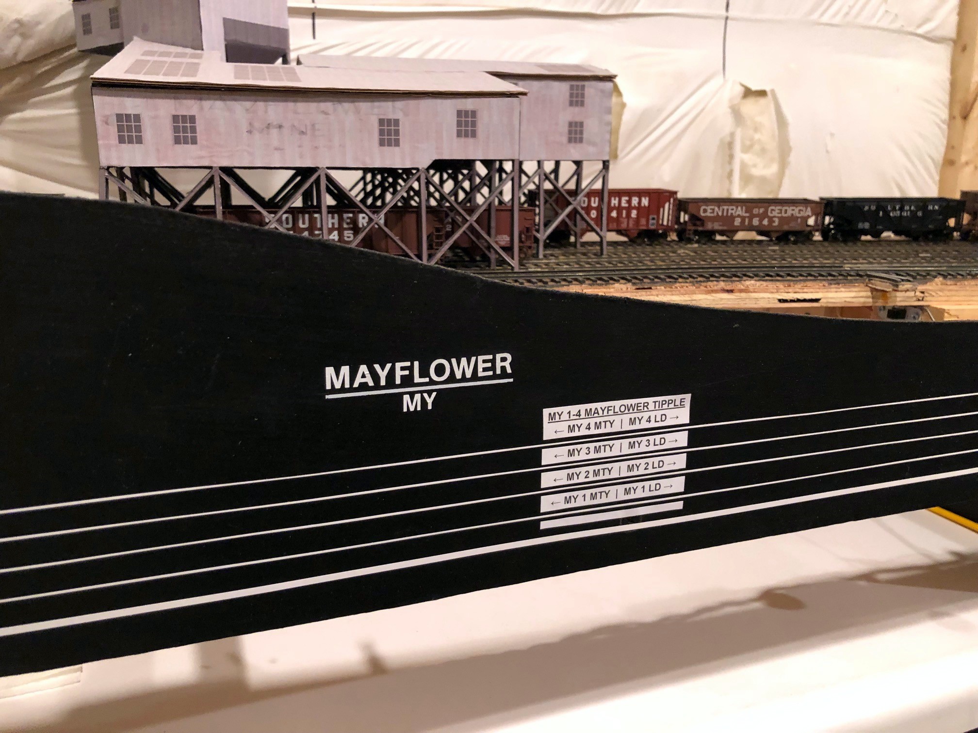
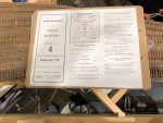
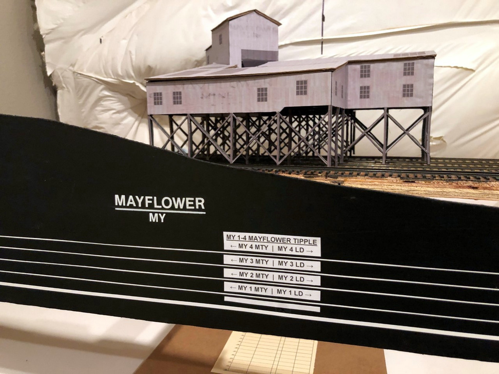
Track diagram and destination markings on the fascia at Mayflower
For the second part of the designator, I could have gone with a second letter/number for the industry and a third designator for the individual track within the industry. Instead, I opted to only use track designators since it still gets the job done and cuts out an extra symbol. So, for a town that had two industries with 3 tracks each, one industry would have tracks 1-3 and another industry would have tracks 4-6. For tracks with multiple industries on a single track, I use “4B,” “4C” etc. for each destination. For example, at the Mayflower tipple, I have a place to spot boxcars or flatcars bringing in material on part of tipple track 4, so this destination gets it’s own “4B” designator to differentiate it from the tipple. Tipple tracks on the prototype inherently have separate areas for “empties” and “loads”–because an operator can easily see if a hopper/gondola is empty or loaded, I didn’t include this in the destination code. I also created a unique track designator for ALL tracks that could be a destination for a car and not just fixed industries–for example, I sometimes use the end of the main at Mayflower as a place to spot a covered hopper, so I’ve designated the last 12 inches of the main as “track 5.” When looking at a switch list, each car bound for a destination on the layout will have a short-hand 3-letter destination code like “MY3”, or in the case of a track serving multiple spotting locations, “MY4B.”
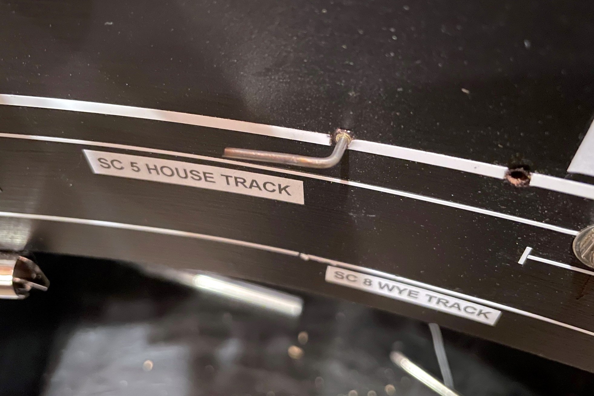
I don’t expect operators to memorize these track numbers, so I place them on a track diagram on the layout fascia. Each town is clearly marked with its name and its 2-letter destination code. Each track is labeled near the turnout throw with its unique number. Each industry or destination spot is marked by a block at the intended spotting location containing its name and the associated track designator(s). In this way, an operator can arrive at a town, look at the fascia, and by checking the switch list know where each car in the train should go.
Track Chart
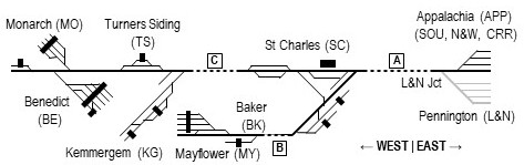
Most railroads also publish track charts for all their lines. The track chart contains useful information like grades and curvature, but it also includes a block diagram for each section of track with the town name and a diagram of all the tracks and their length–this diagram is often drawn in a blocky style using only 0, 45 and 90-degree lines. While crews on my layout don’t necessarily need to know grades and curvature, they do need to have a basic understanding of where towns are in relation to one another. For this, I drew up a simple little track chart of the entire layout for operators to use.
Simple track chart for my St Charles Branch layout
The track chart is laid out in “right = east” orientation and includes the town names (and short-hand designation) in the correct order. It also has a basic track diagram of each town, and I’ve depicted tipple and depot locations (depots are usually drawn on track charts, tipples are usually not). I’ve also included dashed lines for the hidden areas of the layout with letters that correspond to markings on the fascia to help crews better understand logically where their train is headed when they head out of the visible scene. The track diagram also helps them understand how to construct and block their train when heading west of St. Charles.
Blocking Instructions
Southern Blocking Instructions for layout crews
Speaking of blocking a train, prototype trains aren’t put together in random order but rather are assembled into “blocks” based on the destinations of the cars. Switching and local crews are typically required to block their trains in a certain manner to make them easier to handle at the next station or by the receiving crew, so I want to simulate this on the layout as well. Trains waiting in staging are already blocked by me before an operating session (you’re welcome), so the majority of the blocking for crews is for trains taking cars from the upper layout to staging. I could have just left the blocking at “Southern” and “L&N,” but I wanted to give crews a little more prototypical work to do. In addition to the online destination codes, I’ve got multiple destination codes for the Southern’s offline staging yard representing Appalachia, VA (pre-1965) or Andover, VA (post-1965). The loaders in the vicinity of St Charles loaded mainly two types of coal: raw coal for the huge Westmoreland transloader in Appalachia and clean coal bound directly for customers (routed geographically south of Appalachia/Andover) or to connections east of Appalachia/Andover with the N&W and Clinchfield, so all cars that aren’t L&N have a destination code APP, SOU, N&W or CRR to be used by crews to block their trains prior to returning to staging.
The Southern produced a periodic document called Freight Train Schedules and Blocking Instructions. This book has a page for every scheduled freight on the railroad describing how it should be blocked including engines, cars by destination, and caboose. I’ve created a similar document for my crews. In addition to blocking by destination, I’ve also included blocking instructions that place loaded cars on the head end of empty hopper trains and empty cars on the back end of loaded hopper trains, a common prototype practice to improve train handling on grades and curves. I also add a couple basic instructions for the crew to help them understand the train’s purpose and their chores a little better.
Part 3. Putting It All Together
So, in summary, a crew on the St Charles Branch needs a timetable for basic train schedules and area instructions, a clearance card telling them how many train orders they have, at least one train order giving them clearance and specific instructions for their job that day, a switch list telling them where each car should go, a key for each town labeling destination tracks to match the switch list, blocking instructions to get cars ready for the return trip off the layout, and a track chart to help their brains understand the arrangement of towns and tracks. That sounds like a lot of paperwork, but it really isn’t. First, the “key” for each town is on the layout fascia, so they don’t have to carry it with them. Most of the other bits of paper can be combined into a single sheet. For each train, I build a single sheet that has the clearance card and train orders printed on the left, the train description and blocking instructions on the upper right, and the track chart in the lower right. Now, when you add the timetable and switch list, the operator only needs 3 physical sheets of paper. This is still a bit much to carry loose, so I provide each crew with a clipboard for their train. Clipped on the front is the sheet with clearance card/train order/blocking instructions/track chart. On top of that is the switch list. The timetable goes into a plastic sheet protector on the back for easy reference. Add a pencil and an uncoupling tool (attached by Velcro), hand them a throttle, and they’ve got everything needed to operate successfully on the railroad!
Single sheet for crews with clearance card, train order, blocking instructions, and track chartThe one-page timetable fits neatly in a plastic pocket on the back of a clipboard
One final note, when using model paperwork, operators need a convenient place to set things down or else they’ll either leave it behind (bad) or set it on top of the layout (more bad). For those who’ve been keeping up with the layout’s progress, you’ll remember the fascia pockets I build around the layout between the staging and lower levels–this is why they exist. No matter where an operator is in the layout room, they’re never more than about an arm’s length away from a clipboard pocket. How about the throttles? When an operator is handling a train solo, they need to be able to quickly set the throttle down to interact with the paperwork. While there are throttle pockets all around the layout, it’s even better if the operator can just keep the throttle with them. This is where the throttle lanyards that allow an operator to just drop the throttle and let it dangle from their neck come in real handy–this is perhaps the best $1.50 solution to a $25.00 problem on the layout so far!
Conclusion
I’ve taken a little more time on this post because I want it to serve as a more thorough article for those looking for ideas on realistic model railroad operations. I will never claim to have “THE solution,” and there are definitely pluses and minuses to my methods. I do believe this method, though, strikes a good balance that gives the die hard prototype enthusiast or ex-railroader enough sufficiently realistic paperwork to make them feel at home while being limited and simple enough to avoid intimidating newbies or weighing crews down with tedious tasks that only a small percentage of people find fun. While I will continue to refine my operations as the layout evolves, this method definitely meets my goals and needs for the short-term. I’m always learning, so please feel free to post your critiques, feedback and better ideas in the comments section! I’ve also included some jpegs of the blank forms below–feel free to use these for your own personal use. The easiest way to “fill them out” is to copy the images into MS PowerPoint or similar program and create a text box on top of the image.
Clearance card showing how many orders the crew has
An example of my model Southern Form 19 train order
An example of my model L&N Form 31 train order
Southern Blocking Instructions for layout crews
Single sheet for crews with clearance card, train order, blocking instructions, and track chart
My blank Clearance Card
My blank Southern Form 19
My blank L&N Form 31
A train order awaiting pick-up at St Charles
Everything the St Charles Local needs to operate on the layout
The one-page timetable fits neatly in a plastic pocket on the back of a clipboard
A couple of Southern-style whistle posts on the fascia track chart
I thought I’d share a little addition to the fascia–Southern whistle posts. I never thought about this on my last layout because none of my locomotives were sound equipped. Now that I’m moving toward sound, I wanted a way to tell crews when they need to sound the horn for grade crossings. On the prototype, posts are set up on either side of a grade crossing to give the crew enough time to sound off their loooong, loooong, short, looooooooong blast of the whistle or horn. While most railroads used a white sign with a prominent “W” for this purpose, the Southern used a vertically elongated white sign with a stripe, a stripe, a dot, and a stripe (for long, long, short, long). I decided I wanted my posts to be Southern-esque, so I created a simple black-and-white version from basic shapes in MS PowerPoint, sized them to about 1/2″ high, and printed them on a label sheet.
I cut them out and placed them about 15-18″ from the sites of future grade crossings (I have no roads modeled yet) which gives crews about 4-5 seconds of warning at 10 scale MPH, probably about right for the areas where these grade crossings reside. After placing the whistle post stickers on the right side of the track diagram (making them horizontal), I added a little 1/2″ piece of 1/32″ white graphics tape representing the post for the sign to ensure operators can tell which direction the sign is pointing. Once I have scenery, I’ll add some real scale whistle posts trackside, but for now, these will give crews one more prototypical thing to remember while operating their trains.
Patrick Tillery stops at the St Charles depot while running the first-ever L&N CV Local
I’d like to thank Patrick Tillery for informing we he was coming over Monday night to check out progress on the layout which became the catalyst for the first multi-train operating session on the St Charles Branch! Despite some major obstacles such as having to reach under or across the layout to throw switches and a couple turnouts and cars that were acting up under their first real use, we managed to run 3 trains: the St Charles Local, the St Charles Switcher, and the L&N’s CV Local. These are the three primary trains on the layout during “busy times” across all eras of the layout–the timing of the trains may vary, but each serves the same basic function.
The St Charles Local is a scheduled train that runs between Appalachia/Andover, VA and St Charles. In leaner times, it serves as the mine run for the St Charles area branches. In heavier times, it serves to shuttle empty hoppers to the small “yard” at St Charles and pick up loads retrieved by the St Charles-based mine run. This is the “big train” on the layout and the only train to ever be assigned more than two locomotives.
The St Charles Switcher, known in some eras at the Black Mountain Local, is the mine run based out of St Charles that serves the area loaders. It picks up empties dropped off by the St Charles Local and plies the numerous branches and tipples dropping off empties and picking up loads. This train is the star of operations on the layout and the only train that will normally have a crew of two (conductor and engineer).
L&N CV Local runs around its empties at Mayflower with Patrick at the controls–the C420 is still in TC colors
The L&N Cumberland Valley (CV) Local is the only other scheduled train on the layout. This train works the old L&N mainline between Corbin, KY and Appalachia, VA including the modest coal loadings of the Middlesboro, KY area mines and the St Charles Branch. The L&N has trackage rights over the portion of the St Charles Branch from L&N Junction (Pocket), VA to the ends of the branches beyond St Charles which it reached via a short L&N branch between Pocket, VA and the L&N’s CV mainline at Pennington, VA. Despite several loaders in this area, the prototype CV Local never seemed to need more than a single locomotive, an RS3 or a C420, to handle the handful of hopper loads bound for the L&N.
Last night’s operating session took about 2 real hours. Patrick took the first train, the L&N CV Local, up to Mayflower to swap out 4 empties for 5 loads. Leading the train was Alco C420 400 still in Tennessee Central colors (it’s bound for the paint shop soon, but the L&N used ex-TC C420s on this line because they were the lightest on the railroad). The CV Local had to first stop at the depot track on St Charles wye to pick up an extra set of orders from the Southern dispatcher. This job took about 40 minutes from start to finish. After the L&N CV Local cleared St Charles, the St Charles Switcher with me as engineer showed up with 18 cars – 16 empties, a covered hopper of fertilizer for Mayflower, and a boxcar for the team track at St Charles. It took about 20 minutes to assemble the loads from the previous day and replace them with the fresh cars in the tiny 3-track yard. A derailment kept the L&N CV Local waiting for a few minutes until the superior train on the timetable was finally able to depart for Appalachia.
With the home rails now to itself, the St Charles Switcher left the house track next to the depot to serve four tipples with Patrick as engineer and me as conductor. We worked the two local tipples first, JAD Turner and Cavalier, before swapping out the boxcar for a now empty flat on the team track. With the locals taken care of, we swapped roles and picked up the remaining empties an the load of fertilizer and headed up the branch to Mayflower. At Mayflower, it took two sets of run-around moves to place the empties above the tipple and swap out covered hoppers on the tail track. One more run-around set us up to work the stub track at Baker before assembling all the loads and departing town. A little blocking back at St Charles yard rounded out the job which took nearly an hour.
All told, we got 2 hours of operations out of just 1/2 the layout–not bad! Despite working out a few kinks in the rolling stock and trackwork, the overall track arrangements worked well for the jobs–they required enough moves to keep operators thinking and having to make smart moves without being frustrating for lack of sufficient track. I underestimated how handy it is to have a wye for turning trains working the yard instead of having to run around the length of the train. It was also the first major use of paperwork on the layout, something I’ll describe in more detail in a future article.
I’m so glad Patrick was up to playing guinea pig for the first session, and I’ve now got a new punch list of stuff I need to fix before attempting this again. All part of the learning process!
Finished fascia and labels at MayflowerI set a combination square to the right height and slide it along the bottom of the fascia while dragging a pencil across the top to draw straight lines for the track diagram
Working on the fascia is very mundane and unexciting, but as a human factors engineer by education, I take my fascia very seriously! On most layouts, the fascia is the primary interface between operators and the layout. It’s often where we place controls and place names, and it’s also a blank canvas we can use to help our operators better understand the scene they’re interacting with. Like many who perform switching operations on their layouts, I like to use the fascia to help operators understand as much as possible about towns, tracks and industries to aid in making their switching moves.
As far as construction goes, my fascia is just sheet Masonite fastened to the benchwork with drywall screws. I cut it in thick strips that will account for all the vertical scenery contours along the front edge. Where there are noticeable gaps or indentations from the screws, I touch things up with lightweight spackling compound and wipe it smooth with a damp cloth after letting it harden for about an hour–this saves a lot of time sanding later. Then I draw in the ground contour with a pencil and cut it with a jigsaw. A little black paint, and things are ready for the operator features.
All the Mayflower switch controls installed–they’re at different elevations to line up with the track diagram that will be installed on the fascia
On my last layout, I drew the track diagram onto the front of the fascia, and it worked so well I decided to continue it on my new layout. It’s essentially an elongated track diagram like you’d find in a railroad track chart that lines up with the adjacent track and switches on the layout. I draw the lines parallel to the bottom of the fascia 3/8″ apart. To draw them, I’ll set a combination square so the end of the ruler is at the exact height I want when the square is pressed against the bottom of the fascia, then I’ll run the combination square around the bottom of the fascia while dragging a pencil along the top to draw it onto the fascia. I draw the switches onto the fascia at 45 degree angles with the convergence drawn where I want the switch control rod to be placed (directly perpendicular to the switch mechanism usually). One lesson learned from my last layout I was able to incorporate into this one is that the “straight” line through a switch control is the “normal” position of the switch while the “divergent” line represents the “thrown” position. It required a little “wiggling” of the track lines in the yard ladder to make this work, but it’s intended to help operators understand how to set the switches before departing a town.
Finished fascia labels with the town name and siding identifiers for the Mayflower Tipple
I installed the switch control rods (see full article on switch control mechanisms here) after the lines were drawn but before placing the graphic tape on the fascia to represent the tracks. I use two sizes of white graphic tape for the tracks, 3/32″ to represent the main, and 1/32″ to represent sidings. This offers another visual clue for operators so they know which tracks not to block and what to leave clear after leaving town. Next come the labels. Every town on the layout has both a name and a unique 2-letter destination code for routing cars. In this case, Mayflower is represented by “MY.” Within each town, each track has a unique number, for example, MY 1 is the tipple track for the Mayflower Tipple closest to the main. For tipples, I also designate where the empty (MTY) and loaded (LD) cars go, so an empty hopper destined to be loaded on Mayflower’s outermost track would need to be placed at MY 4 MTY. Towns are labeled with large dry transfer lettering with the town name above a line and its destination code in smaller letters below. I also cut a small gap in each track tape on the fascia near the switch and use dry transfer numbers to label each track by number. Industries are given white labels with black lettering that gives the industry name, town initials, track number(s) and MTY | LD track dividing line if needed (see picture of the Mayflower Tipple and its labels). If two or more industries are on the same track, I use a “B,” “C” or so forth to denote each spotting location. In the case of Mayflower, I’ve identified a spot on load track 4 where I might have operators occasionally spot cars of supplies and a spot on the tail track of the main where I might have them spot covered hoppers of AN–each of these spots has its own industry label adjacent to the correct track on the fascia track diagram to make it clear where to spot the cars.
There’s nothing really novel here, but I do think this method of using track diagrams on the fascia and integrating switch controls, town names and industry track designators with unique operational codes goes a long way toward making the layout more intuitive and operator-friendly.
Roughed in masonite fascia awaiting sculpting
Here the fascia has been cut to shape, sanded, and painted
I set a combination square to the right height and slide it along the bottom of the fascia while dragging a pencil across the top to draw straight lines for the track diagram
All the Mayflower switch controls installed–they’re at different elevations to line up with the track diagram that will be installed on the fascia
Extra wood glued behind the fascia supports the switch throw rods and makes the fascia stronger
Nearly final fascia in Mayflower with the track diagram in place
Finished fascia and labels at Mayflower
Finished fascia labels with the town name and siding identifiers for the Mayflower Tipple
My son, Drew, was the engineer for the first mine run on the layout, a “Black Mountain Local” working Mayflower and Baker
Saturday was a big day–the first operational train worked the first loaders on the layout. It was a “Black Mountain Local” with me as conductor and my son, Drew, as engineer. Things overall went pretty smoothly with only a single derailment in the entire session (not bad for the first time operating on hand-laid track). Our power was GP38 2877 and GP30 2534. We picked up our train of 13 empty hoppers and a single loaded ACL covered hopper (AN for the mines). Awaiting us in Baker were 4 “yellow ball” loads for the transloader in Appalachia followed by 8 loads at Mayflower and an empty covered hopper.
The tracks at both Baker and Mayflower are stub tracks (prototypical), so most of our time was spent pulling loads to clear tracks and running around empties 5-at-a-time in the single run-around track. It was a great time to teach my son about run-arounds, delayed couplers, and how to think through switching moves. Despite the lack of scenery or even operational throws for the switches (I had to reach under and throw the mechanisms directly), it was 30 minutes of pure joy more than 3 years in the making (since we moved in). We finished the shift with the entry of this “milestone” marker on the benchwork to commemorate the event.
“Milestone” entry for the first mine run worked on the layout