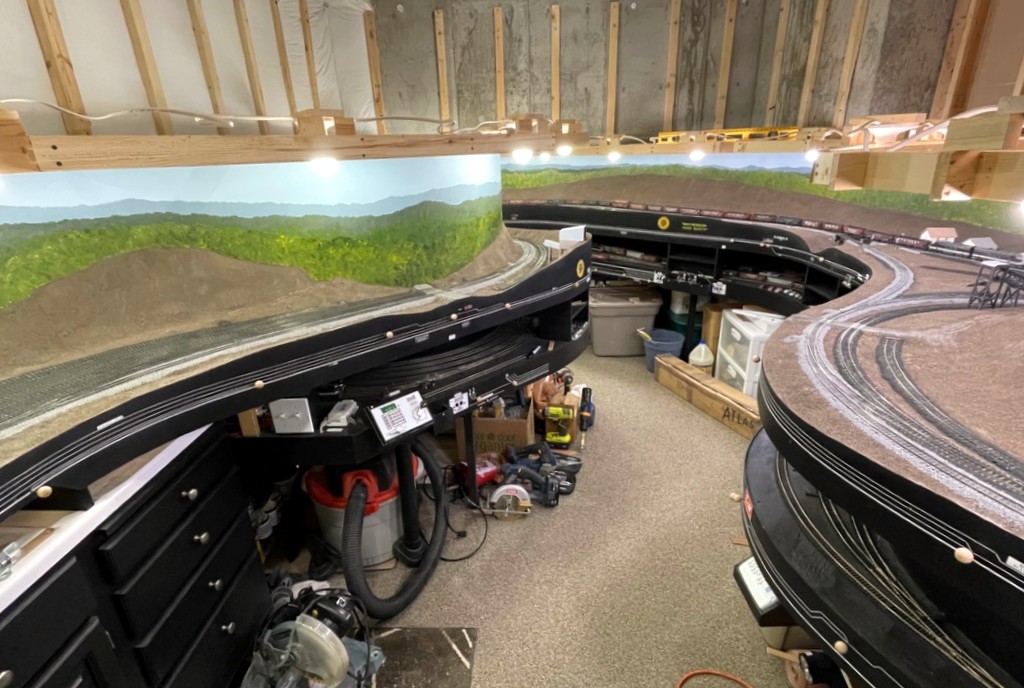
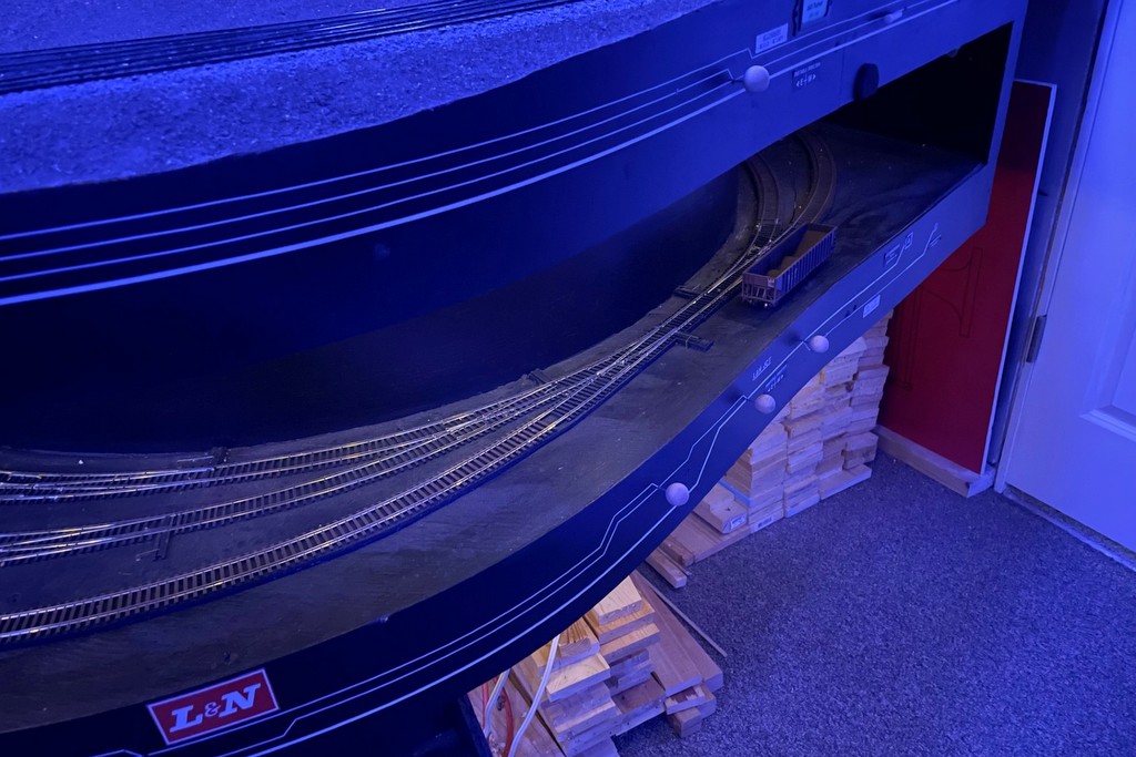
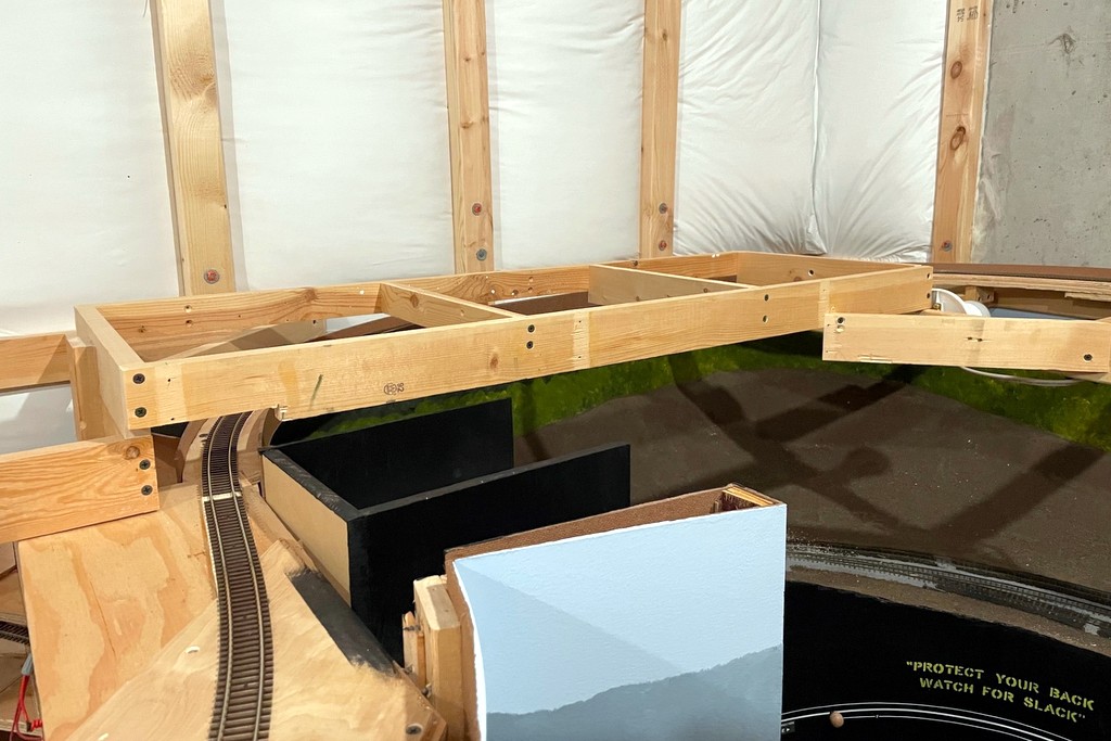
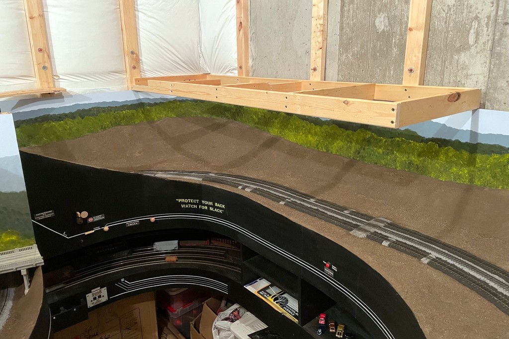
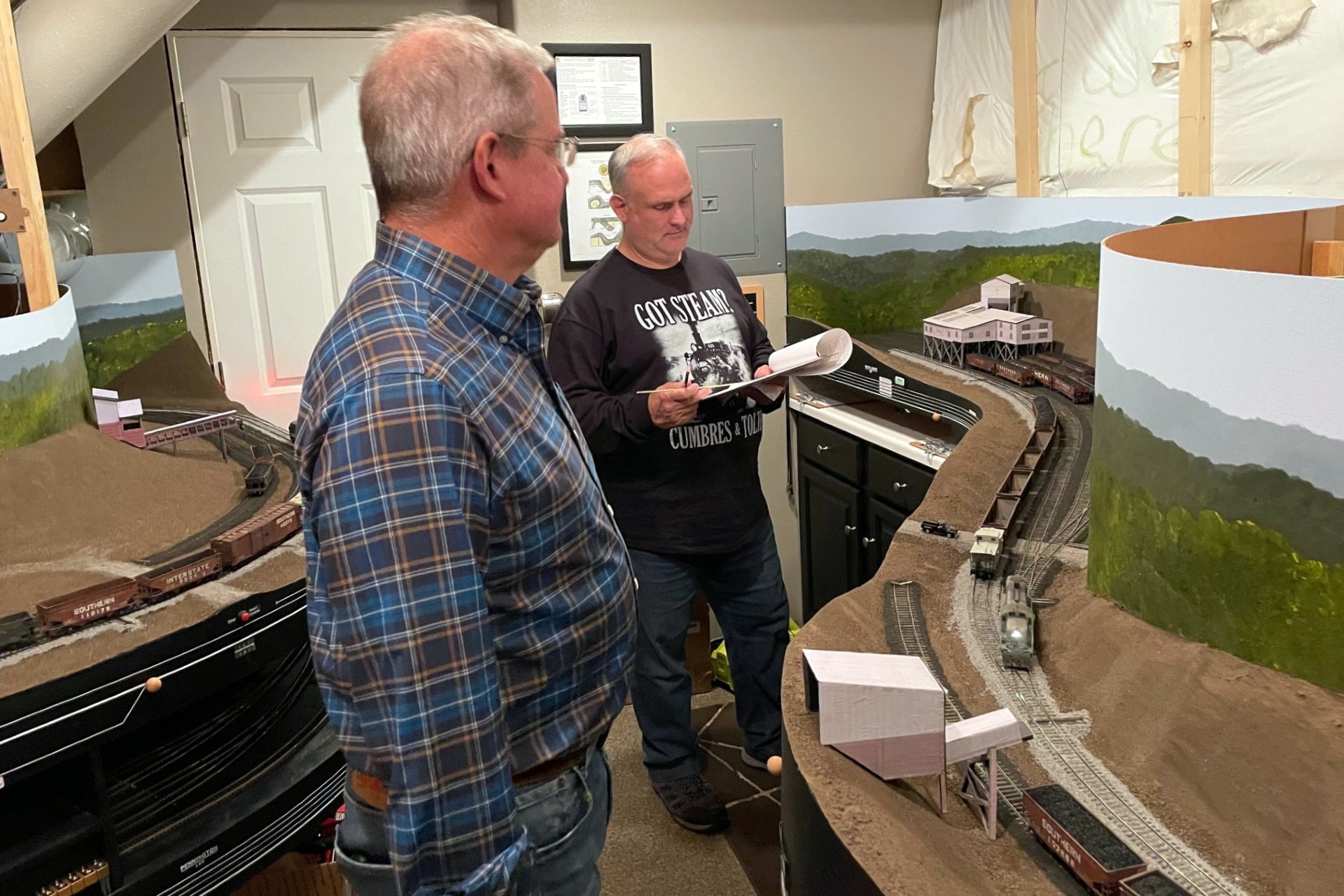
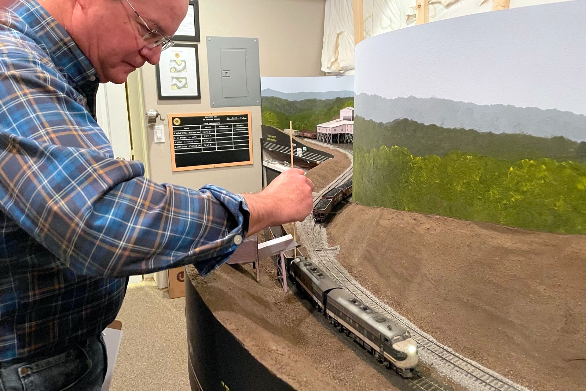
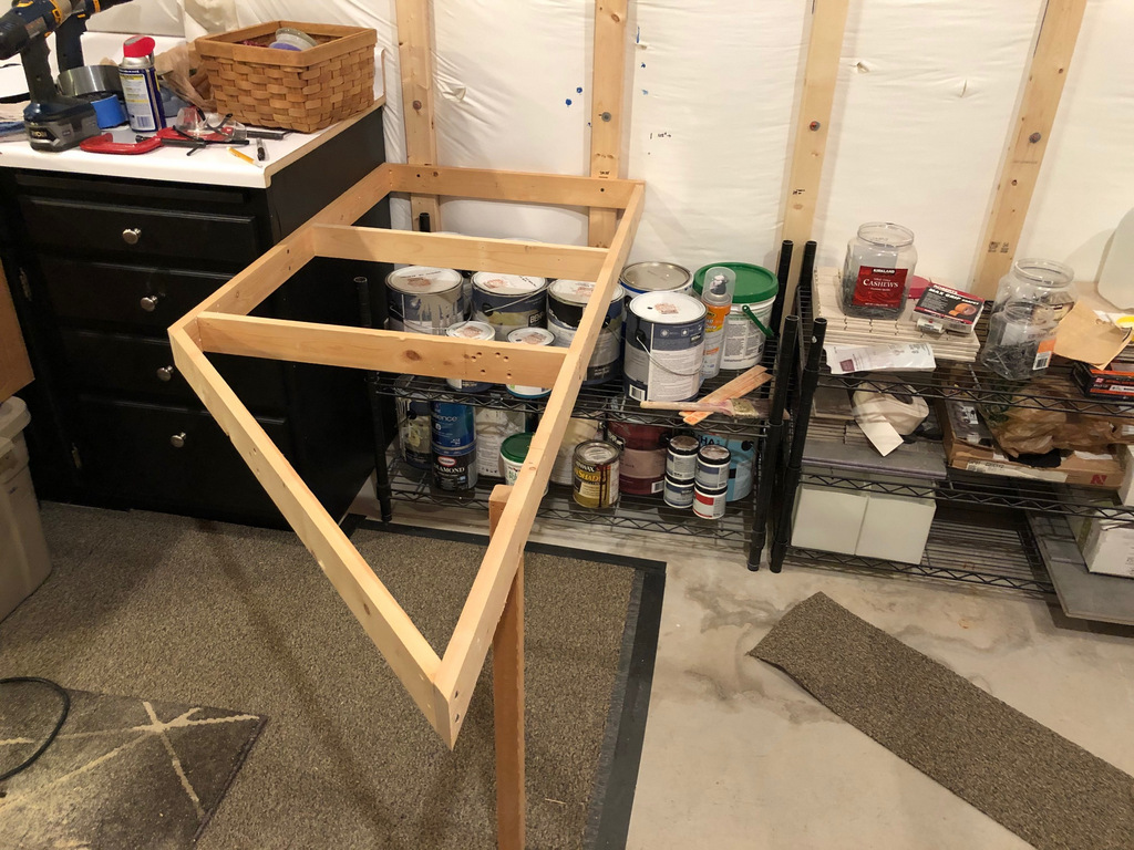
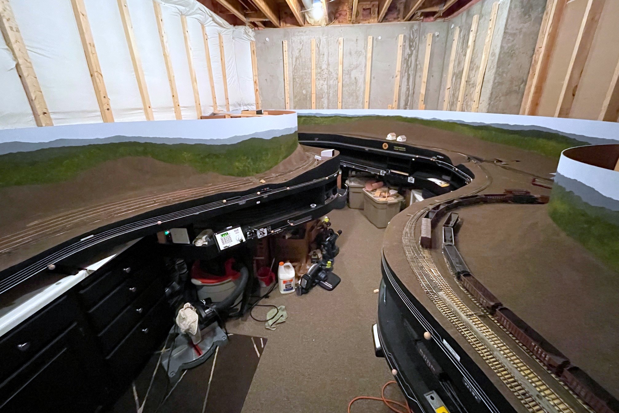
Upper level benchwork showing the new lighting fixtures for the lower level
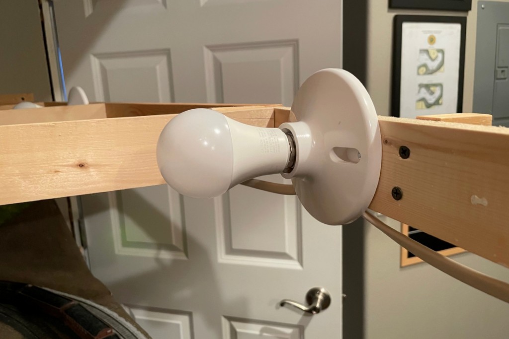
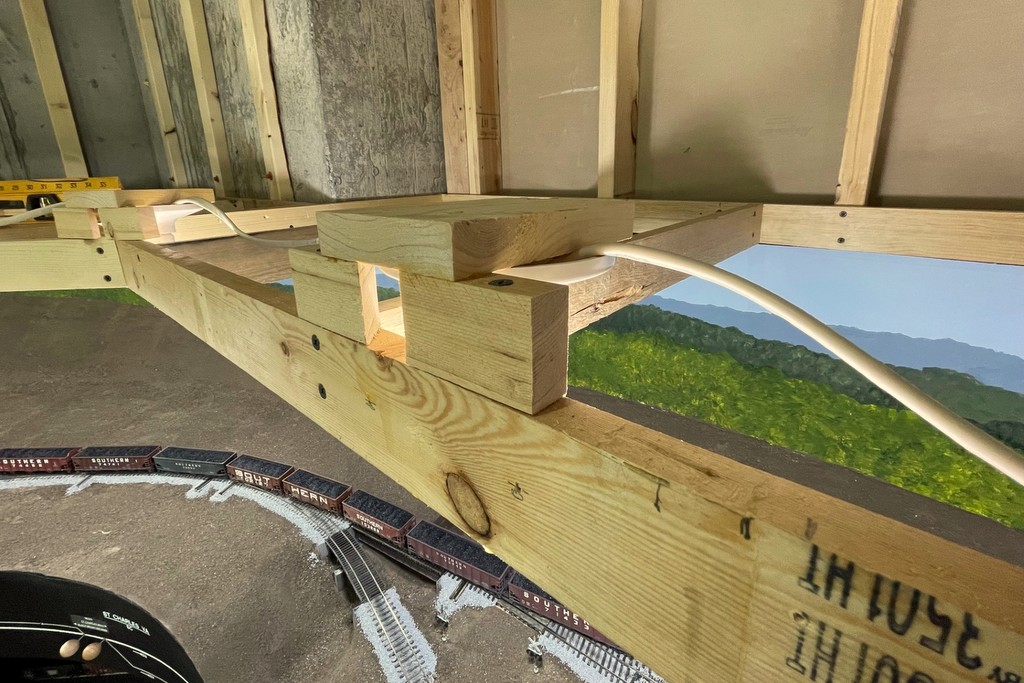
A few weeks ago I posted about installing the first lights on the layout. I’m using multi-color, dimmable LED smart bulbs, and one of the surprises I faced was the limited angle of “light throw” from the LEDs compared to incandescent bulbs when mounted horizontally like they were on my last layout. I experimented with ways to get the bulbs to sit vertically and came up with this style of lighting fixture. It’s a simple setup with two blocks of 1×2″ lumber about 3″ long and a piece of 1×4″ lumber about 5″ long cantilevered off the top. The 1×2″ pieces are cut 45 degrees on one end which allows the plastic fixture to snuggle into the blocks above the benchwork edge to get the lightbulb as close to the layout edge as practical. The globe area of the bulb now sticks out about 1″ below the benchwork which does wonders for eliminating awkward shadows from the benchwork (this 1″ will be covered by fascia eventually so you’re not staring at bright bulbs while running trains). The major drawback to this method is it requires a lot of vertical space, so I’m having to adjust my track elevations on the upper deck upward about 1″, and I’m having to strategically space my lights to avoid areas where creeks and valleys will run all the way to the fascia.
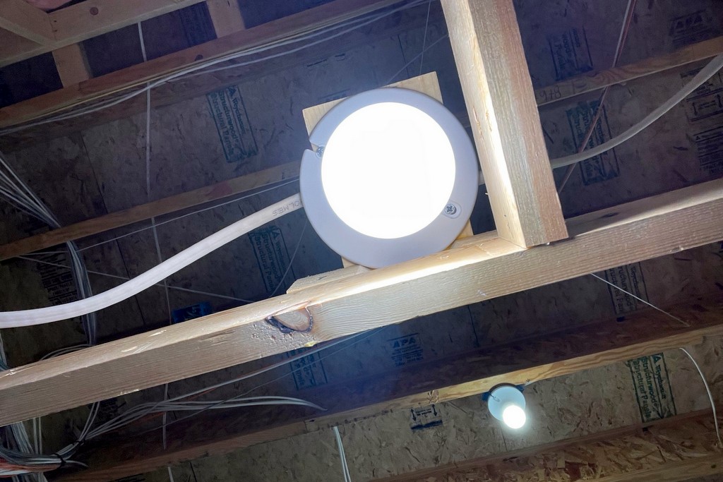
The original horizontal orientation for the simple plastic screw-in basesThe new lighting fixture that casts more light downwardView of the new fixtures from below
Despite this drawback, I’m REALLY happy with the lighting this provides and the flexibility inherent in the multi-color smart bulbs! Like my last layout, I’m placing them about 24″ apart to get good lighting into all the spaces. They’re 60W equivalent bulbs, so when they’re on full power, it’s really bright… too bright. I find dimming them to about 65% is just about right, but the beauty is I can change this at any time using my phone app that controls them. I can also adjust the light temperature anywhere between 2700-6500K to get a good “daylight” feel, and I’ve found a nice blue/cyan color I can turn down to 1% brightness to get a moonlight feel and still be able to see what’s going on. To counteract some of the shadowing on the extreme aisle edge of the lower deck, I installed the same LED smart bulbs in my four overhead fixtures–they can be tuned to the same color as the layout lights. I also installed a smart dimming outlet I can run from the same app that controls the strings of cheap LED soft white Christmas lights under the layout that illuminate the staging yards and aisles.
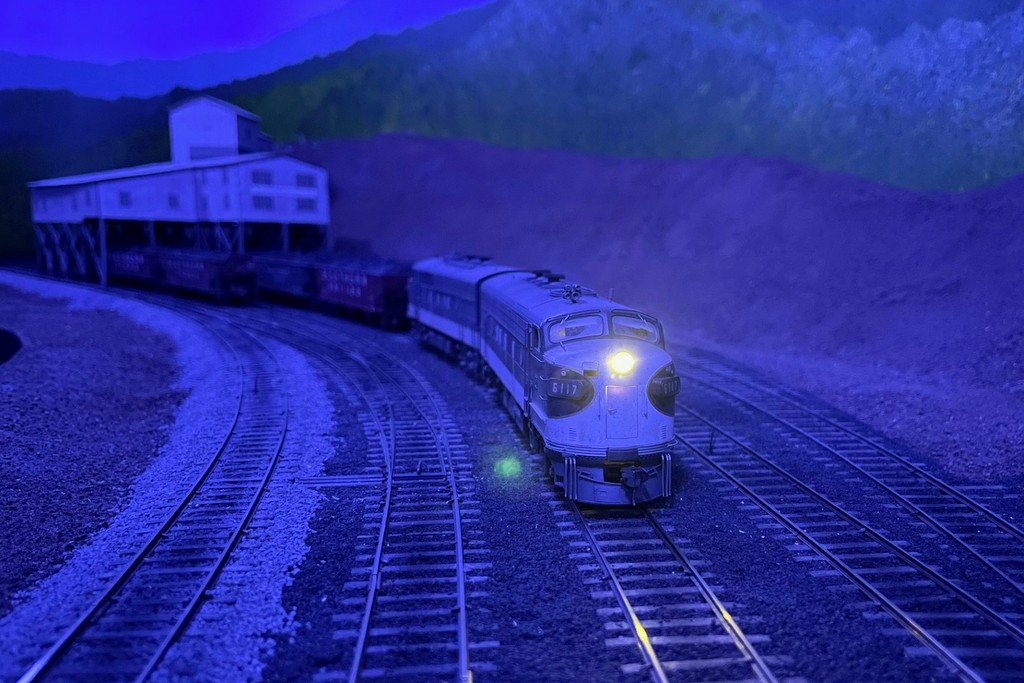
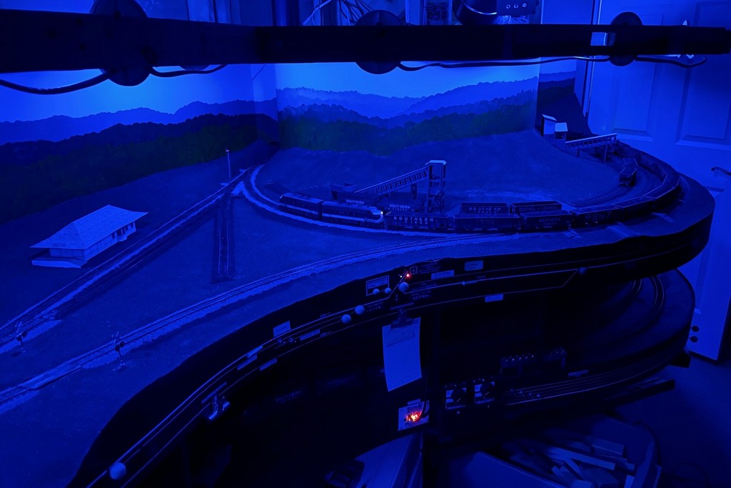
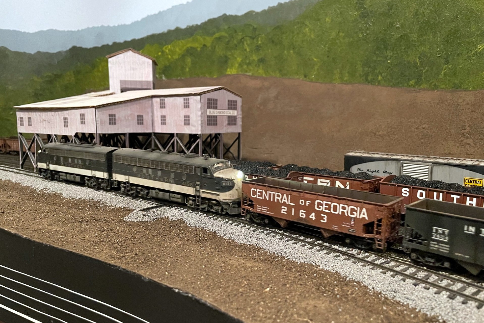
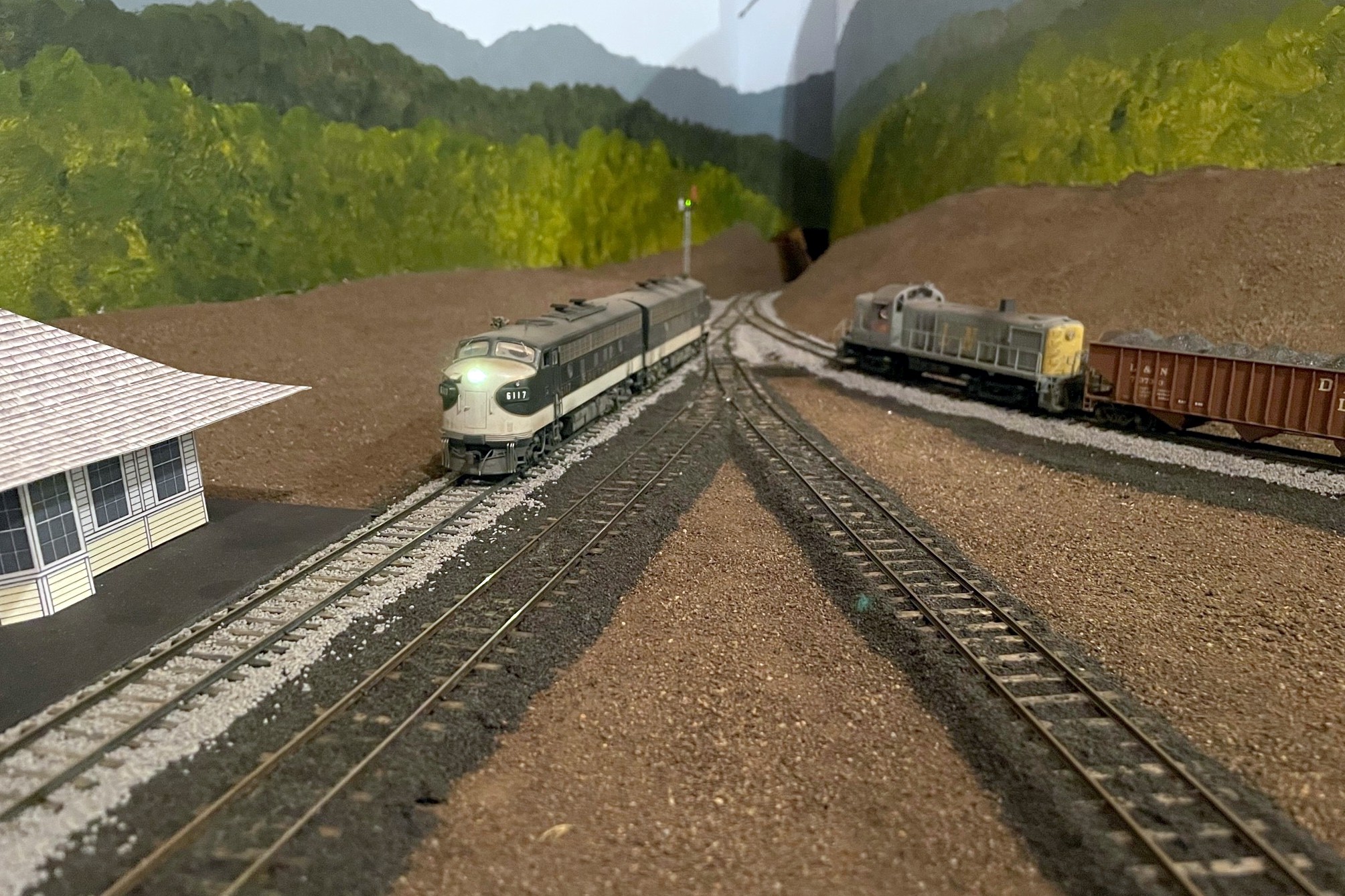
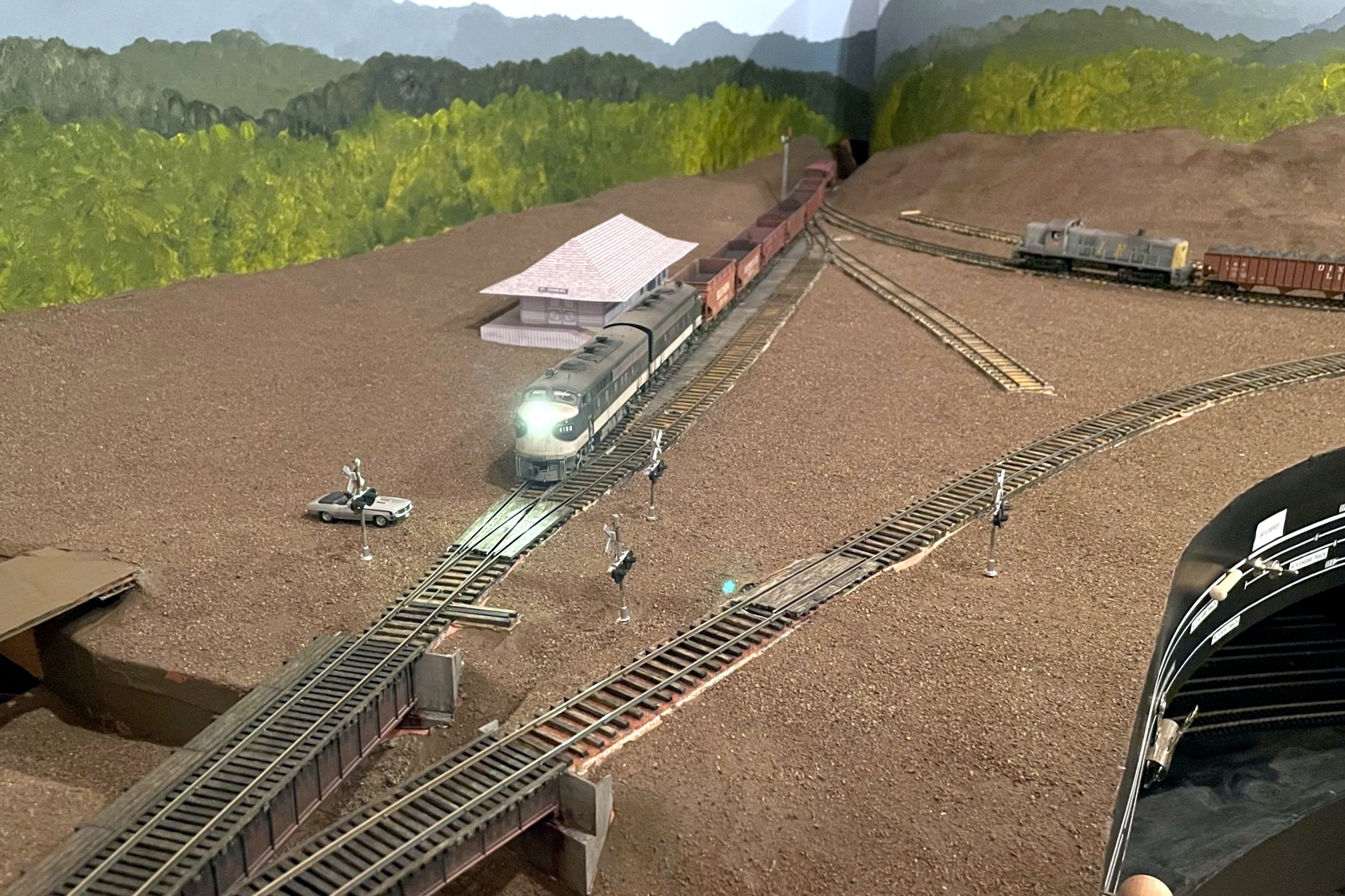
The new LED layout lights can be used to simulate a wide range of lighting conditions including “moonlit night”A pair of F-units are working late into the night to finish up the work of the Black Mountain Local
I’m running the lighting with three groupings in the app, one for “main” (all LED smart bulbs), one for “overheads” (just the four overhead lights), and one for “aisles.” This setup gives me the ability to control the intensity and color going to the layout, and it allows me to turn the overheads to full brightness even if the lighting closer to the layout is dimmer. The aisle lights can be turned off or on independently, and the brightness can be adjusted based on layout lighting conditions.
Cheap strings of LED Christmas lights light up the aisles and staging yardsLED Christmas lights illuminating the paperwork area under Mayflower
All told, the layout will need about 45 of these bulbs. At ~$6.50 apiece, it’s not the cheapest option, but I’ve been very happy with the results! Hopefully I’ll get at least a few years out of the bulbs before having to replace them. I’ll keep playing around with the colors and intensities and seek feedback from other operators and will share what I learn over time.
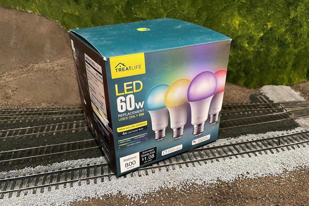
Here’s what I’m using, TreatLife 60W equivalent (9W actual) multi-color LED smart lights
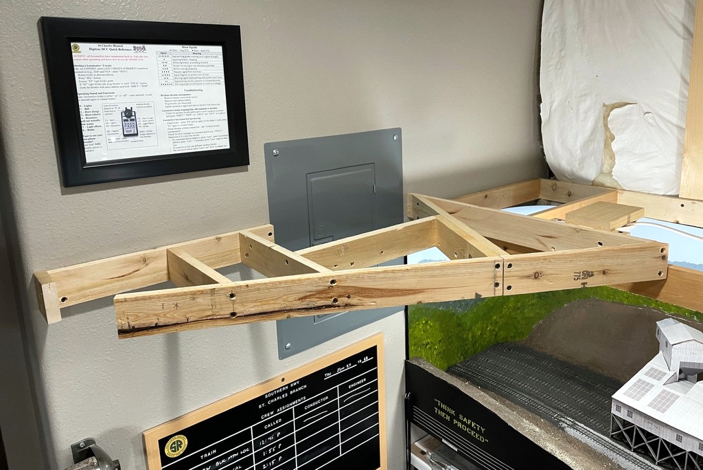
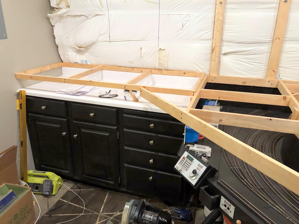
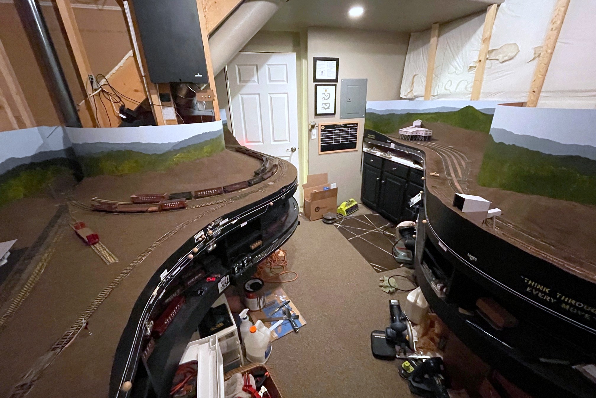
A shot from the door of the completed upper-deck benchwork
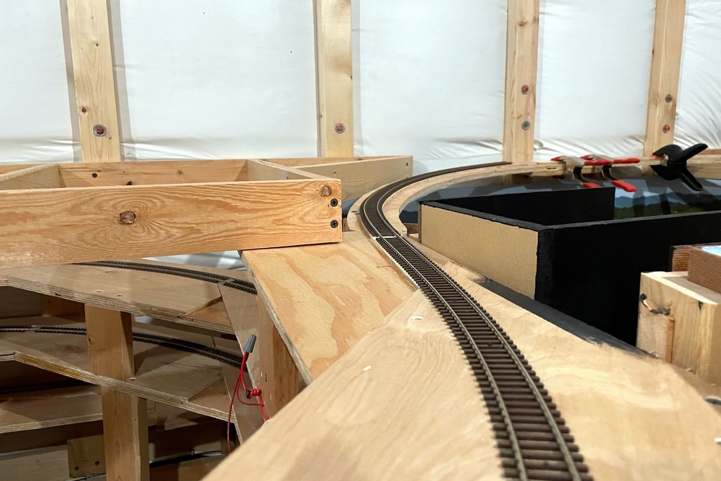
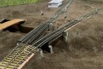
The layout passed another milestone this past weekend–the upper-deck benchwork is now complete! Most of it was pretty straightforward, and the average deck height (top of benchwork) is 60″. A few sections required some creative engineering and some non-90 and 45 degree cuts. One tricky section was the top of the helix where the tracks transition through the upper deck benchwork. I used a piece of elevated benchwork and a plywood bridge to make this transition.
This was a challenging section to engineer–the track comes off the helix, ducks under a piece of elevated benchwork, then runs on top of the upper deck
Another tricky section was the last piece which holds the tail track for the switchback to Benedict at the end of the line. This piece goes in front of the basement breaker panel, so I had to engineer it so the door can be easily and fully opened and accessed, and I designed this section to be removable in case any major work is required someday. As you can see from the first photo, the lighting is in but very visible–these will be hidden behind fascia once the upper-deck trackwork is in.
This was the last piece of benchwork for the upper level. This piece allows the breaker box to be opened, and it’s removable in case there are bigger issues
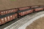
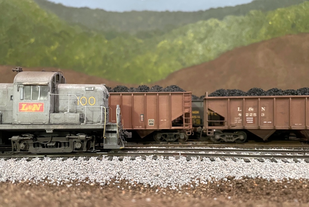
Here’s a representative CV Local with an RS3, 11 hoppers, and a cab nearing the top of the grade
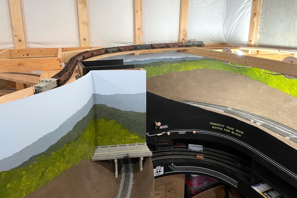
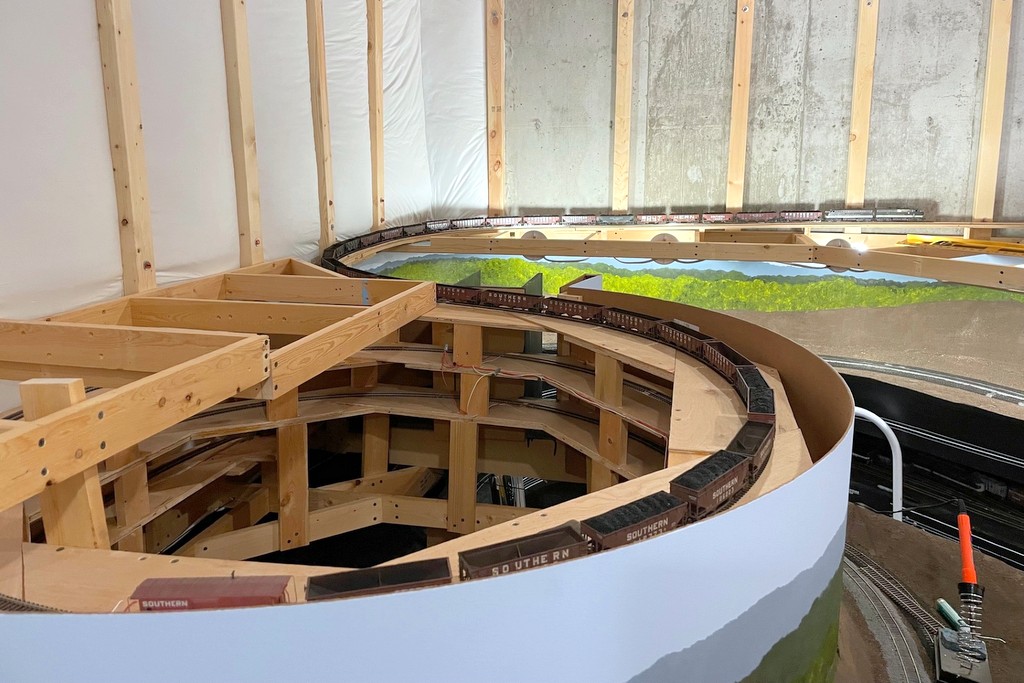
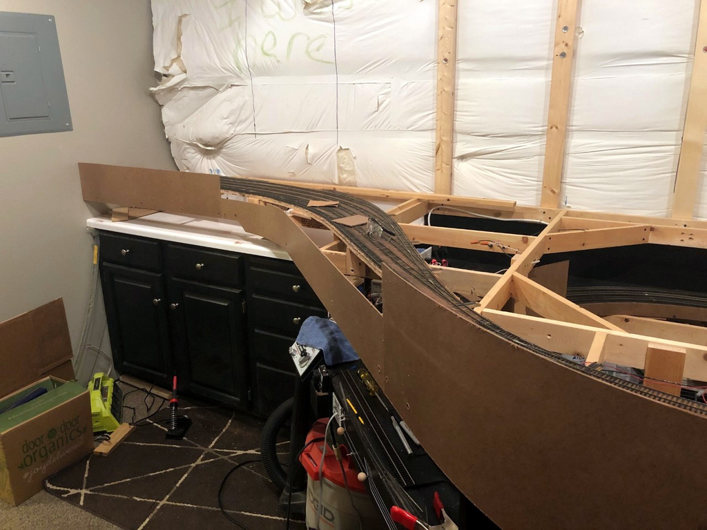
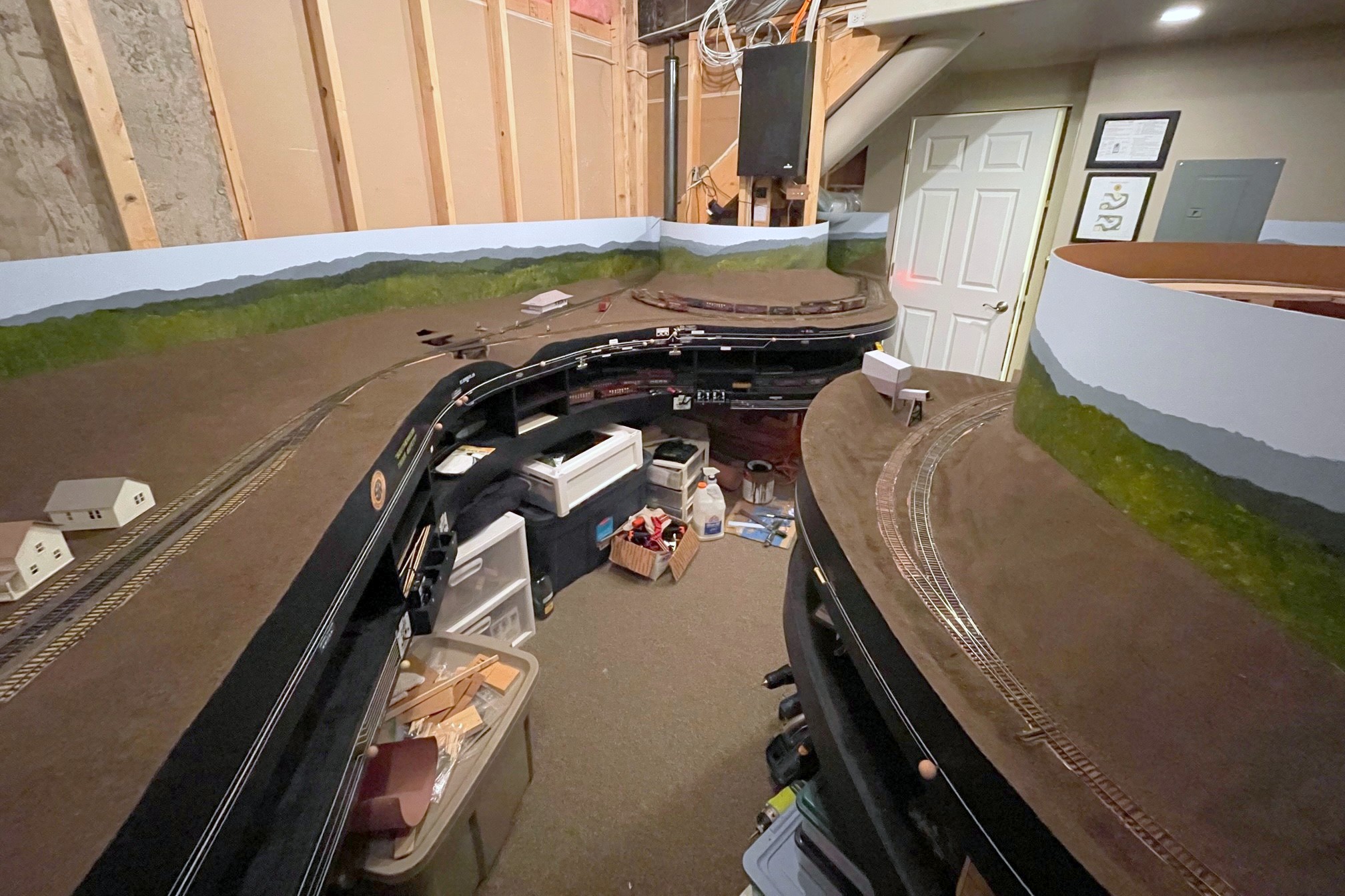
With a portion of the upper-deck benchwork in place, I was able to complete the connector track from the top of the helix to the top of the grade along the back of the layout. The moment of truth had arrived where I would figure out if a key assumption I had made would hold true. My helix is aggressive: 24″ radius and 3% grade! At the top of the helix is an S-curve into another 24″ curve in the opposite direction and a short straight section to reach the top of the grade. Based on experience with the first helix (also 24″ radius and 3% grade), I estimated my lightest engine could pull about a dozen empty hopper cars and a caboose up the helix. The lightest engine is an Athearn RS3 used on the CV Local, and in the 1960s and early ’70s, this job only hauled a handful of cars onto the St. Charles Branch, perhaps 6-10 on a given day.
Here’s the track where it exits the helix and continues up-grade to the right through the upper-deck benchwork
I loaded up an RS3 with 12 cars (including 3 really heavy Tangent cars) and headed for the first helix. With the Tangent cars, the RS3 stalled out on the grade–uh oh! I removed one hopper and tried again. Thankfully it was able to climb the first hill, albeit with the throttle at 1/4 speed and the Tsunami2 howling at run 8! After a brief respite of relatively level track in St. Charles, the train attacked the second helix to the upper deck. Three-and-a-half turns and 20″ higher, the train exited the helix and entered the S-curve, coming to the crest of the grade without stalling. So, 11 cars is my current limit, and while it’s slightly less margin than I had hoped, it’s good enough that it won’t restrict my operating scheme.
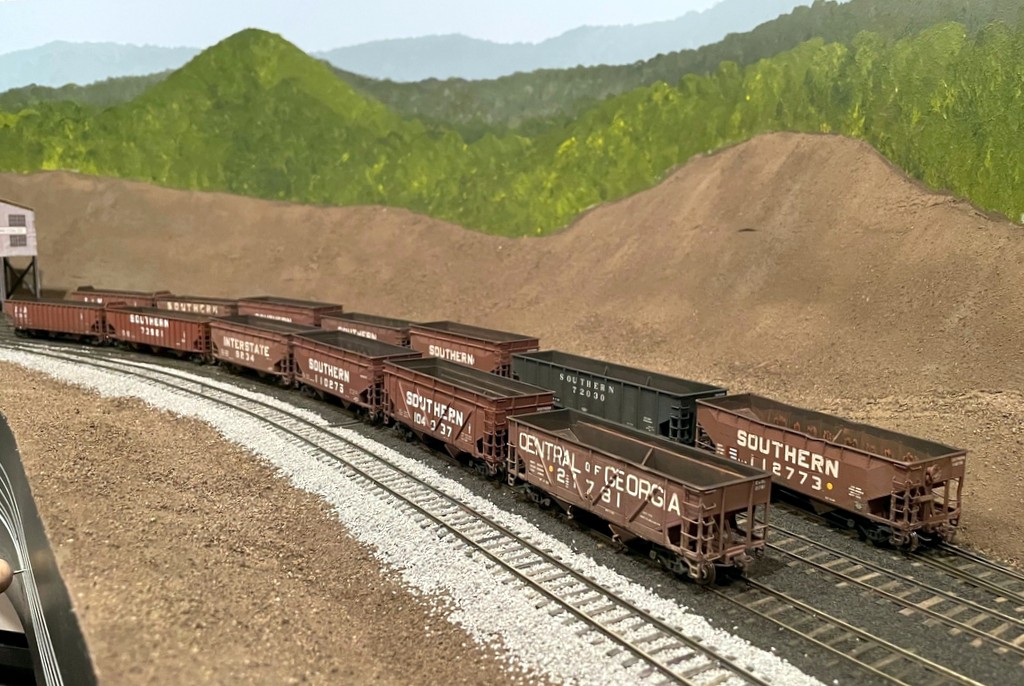
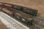
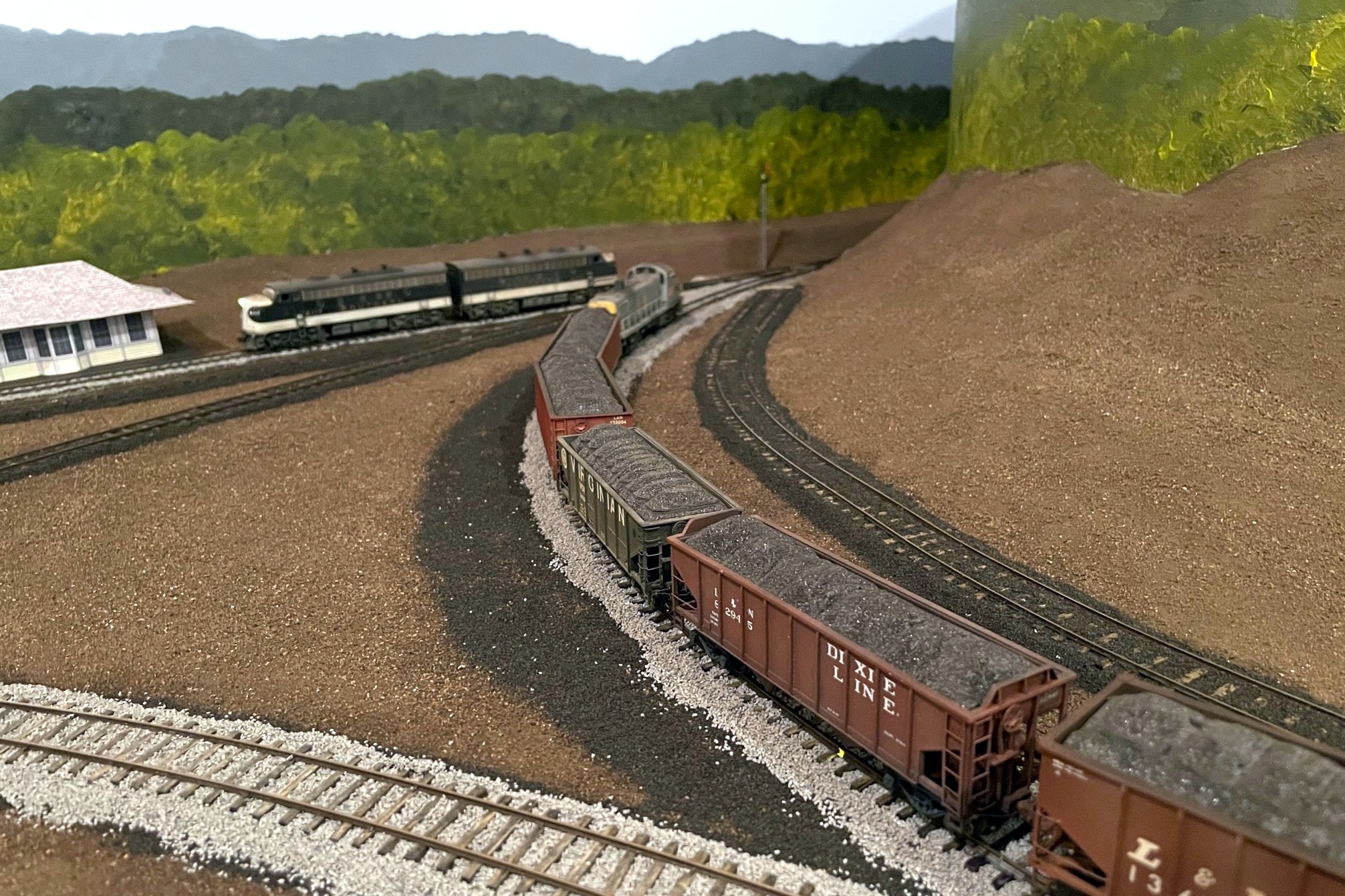
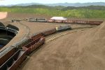
Two Southern F-units have no trouble pulling 33 cars to the top of the 3% grade
Just to be sure, I latched a pair of Intermountain F7s to 33 Southern hoppers and tried the same thing. No problem! Two locomotives have plenty of power to haul more than enough cars up the grade. It was cool to see trains actually running on the upper deck, even if the section they’re currently in will be hidden by hills.
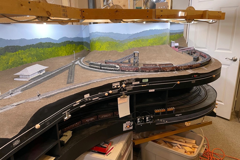
The first layout lights are in! Here’s the “cool white” that I like for daytime
While my light is nowhere near as impressive as God’s light in Genesis, it still makes me glad to see a little more light on the trains in the basement. Now that I’ve got some upper-deck benchwork in, it opened the way to try out the layout lighting I’ve been wanting to do for a while. I’ve looked into LED strings and other bundled lights, but in the end, I’ve settled on using individual multi-color LED “smart lights” I can control with my phone. It’s not the cheapest solution (about $7 a bulb, and my layout needs 40), but it’s bright, and they’re customizable for a dizzying array of colors and brightness!
This is a more modern evolution of the lighting on my last layout which used cheap plastic fixtures and compact 40W lightbulbs. I was able to recycle the fixtures and wiring for this project, but the technology is so much better than my previous little analog dimmer. Not only are the LEDs brighter, but they run cooler, only use 9W each, and I can get a nice “cool white” that looks a lot more like sunlight than incandescent lights. I was also able to play around with the colors and dimmer, and a wide range of effects are possible including a nice moonlit night and a warm sunrise/sunset. It’s also easy to “group” them so one command changes all the bulbs simultaneously.
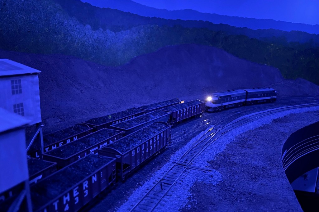
The dimmable, multi-color LEDs can give a lot of different moods like this “moonlit night”
I’ll keep playing with them to try to mitigate the glare spots and shadows. I’m also going to figure out a way to automate going from nighttime to sunrise to day–I’m sure it’s possible with all the Smart Home controls out there now. One thing I hadn’t counted on is the lit portion of the bulb is about 2″ further out from the fixture than the old incandescents. For now that’s creating more shadow along the front of the layout than I’d like. When I put the valance in for the upper deck, I’m inclined to move it out over the aisle a few inches to try to improve this, and I might mount a few of these in the overhead fixtures as well. For now, I’m calling this experiment with 8 bulbs a success, so now I’ve ordered more to keep working around the rest of the layout.
The fixtures for the lighting are simple plastic screw-in basesHere’s what I’m using, TreatLife 60W equivalent (9W actual) multi-color LED smart lights
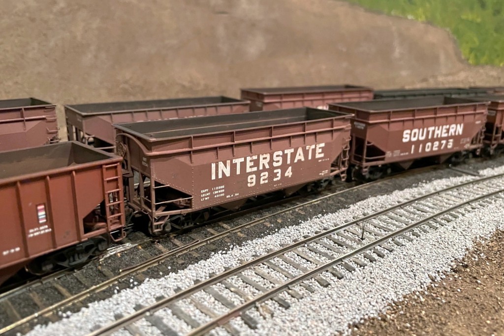
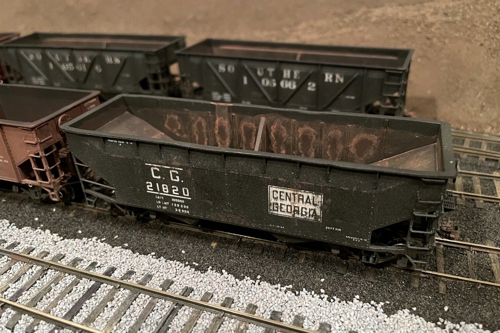
I’ve been on a hopper kick lately, so following close on the heels of the hopper class of January ’24 are these 13 cars comprising the hopper class of March ’24. They were actually built at the same time as the previous hoppers, but these were all custom paint jobs, so it took a while longer to paint and decal them. Among this class are several unique cars including two exact cars I’ve wanted to model since I first saw a picture of them. The first is Central of Georgia war-emergency rebuilt hopper 21781–there’s a photo of this car on railpictures.net at in a line of “yellow ball” hoppers Appalachia in 1978. The other car is Interstate 9234, a hand-me-down offset hopper of unknown origin with arched ends and an 18″ height extension to increase its capacity.
I’ve wanted to build a model of this car ever since I saw it in Ed Wolfe’s first Interstate Railroad book. The Altas offset hopper makes it easy
Most of the cars in this class represent old 50-ton cars relegated to “yellow ball” captive service between local mines and the huge coal transloader at Appalachia, VA where the St Charles Branch joined the Southern mainline. A few cars are regular offsets and war-emergency rebuilds including offset 112773 which spent a lot of time against a 100W lightbulb getting “beat up” to look the part! In addition to the Interstate car, there are four other cars with scratchbuilt height extensions including three offsets and a war-emergency rebuild, representing cars which received their height extensions in the mid-to-late ’70s.
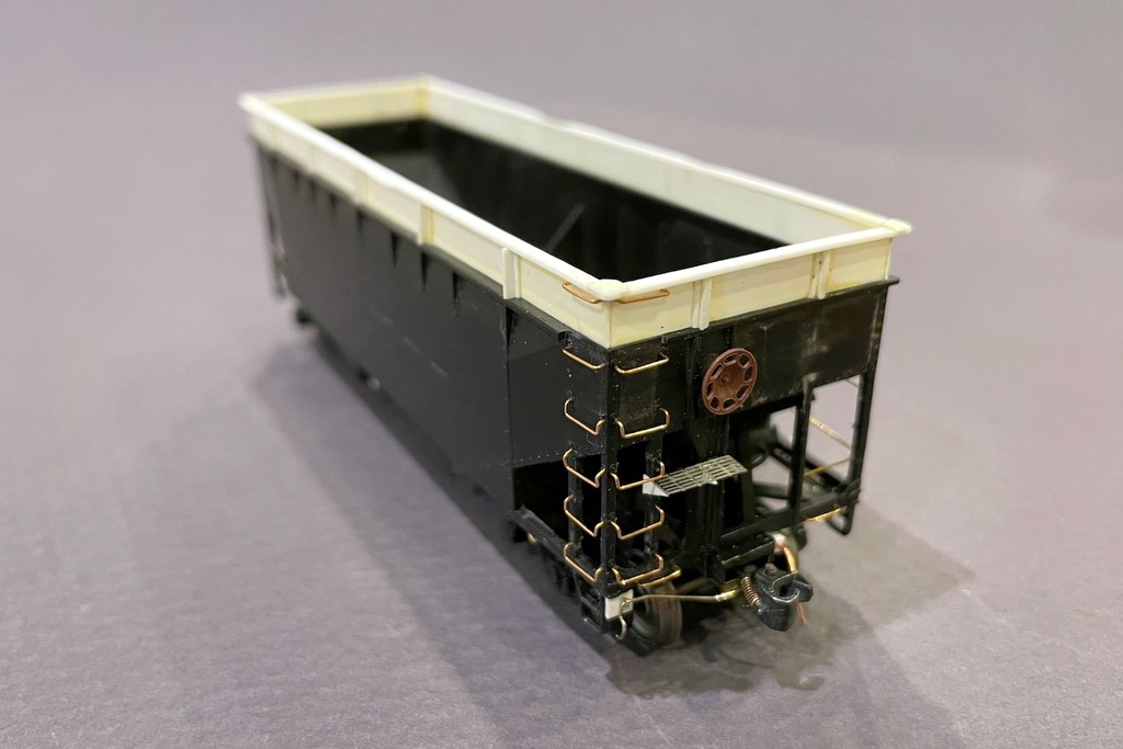
Athearn 34′ offset hopper with an 18″ extension made from sheet and T-shape styrene
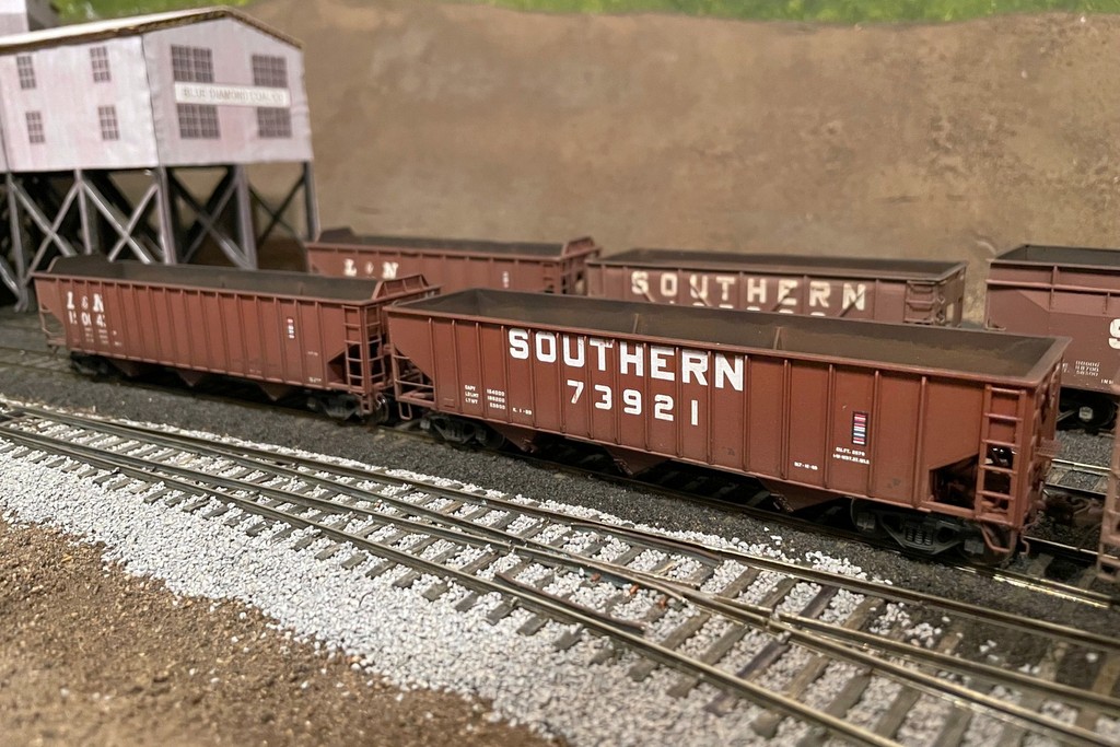
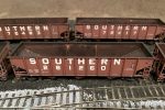
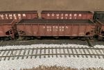
The class includes a couple unique Southern 70T cars as well. The first is a “standard” hopper from the large 70300-73749 class in its original black paint scheme. The first 3,000 or so cars were delivered in black and made it into the mid-’60s before being repainted. Another hopper, 73921, is a Pullman Standard PS3 70T hopper clone that’s been repainted in the more modern Southern scheme from its Railroad Roman scheme. This car, along with the L&N PS3 70T hopper in this set, were kitbashed from Atlas 70T 9-panel hoppers, one by me and one by Patrick Tillery. These were built before the Tangent model was released and have been sitting on the shelf for years–I’m happy to finally have them on the layout! Rounding out the class is an L&N PS3 50T hopper from an old Train Miniatures / Walthers kit representing a repainted car from the late ’60s.
A Southern PS3 clone and L&N PS3, both kitbashed from Atlas 9-panel 70T hoppers
The red cars were painted with either Tamiya NATO brown or a mix of Tamiya NATO brown and flat red–this mix will probably be my standard in the future, and I intend to vary the mixture to get variety in future cars. Never in my life have I done this many decals in one stretch. All told, there are more than 600 individual decals on these cars! Most of them are from K4 decals with a few Mask Island sets. The L&N hoppers are from a Great Decals set and a Curt Fortenberry set I got many years ago. Some Microscale small lettering and ACI labels rounded things out. Most received pretty heavy weathering since most represent non-interchange cars in their last years of service. I’m happy with how these cars turned out, and I’m happy I’ve got 9 more “yellow ball” hoppers to augment the fleet that’s been needing some help for a while.
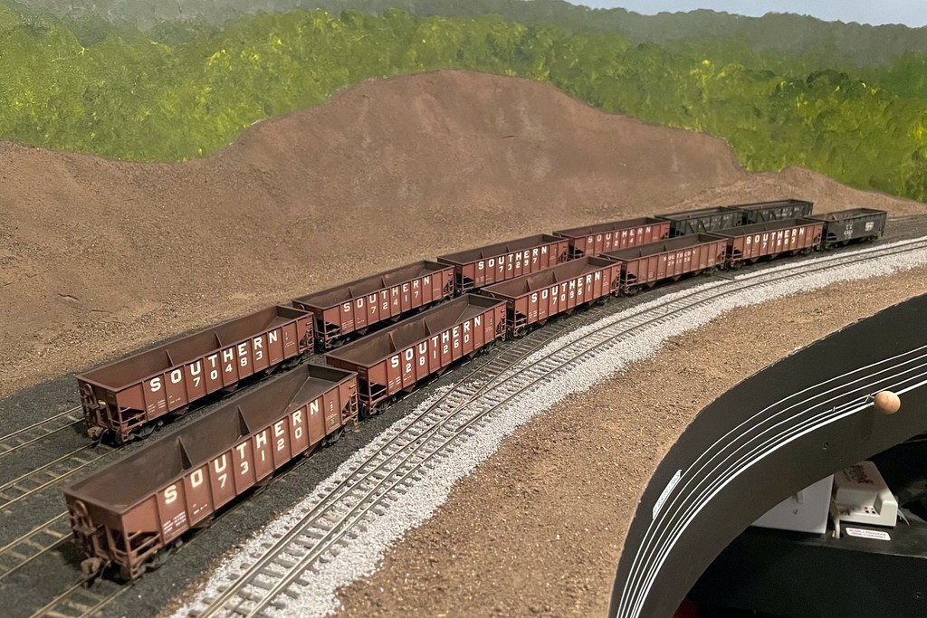
All 12 hoppers from the “class of Jan 24” including 9 Atlas 70T, 1 Atlas 50T offset, and 2 Proto 50T war emergency rebuilds
I’m proud to introduce you to the hopper class of January 2024. This class is comprised wholly of “run of the mill” hoppers for the layout rather than any super-detailing projects. Most are Atlas hoppers including 9 70T 9-panel hoppers and a single 50T offset. Rounding out the class are two Proto 2000 war emergency rebuilds. All hoppers are factory painted, but most have been renumbered, and some have had their round “O” replaced with the rectangular one more appropriate for my era. Renumbering/relettering consisted of carefully scraping off the unwanted digits with an X-Acto chisel blade and adding new decals. I used a tiny paintbrush on the ends to paint in something close enough to the right number to not stand out from a distance.
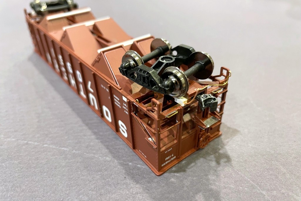
The underside of an Atlas hopper shows the additional details including door bars, train line, grabs, brake platform, and coupler cut bar
The Atlas cars all went through a series of “upgrades” including shaving the backs of the grabs to make them more round and closer to prototypical thickness–this is far easier than replacing all the grabs with wire, and from 12″ away, you really don’t notice that a few of the grabs are still molded onto the body. I did replace all the grabs adjacent to the coupler with wire grabs, and I added homemade coupler cut bars from .012″ brass wire and train lines out of copper from old Cat 5 ethernet cables. Each car also got tack boards made from strip styrene. Since I first posted about the “layout standard hopper” four years ago, I’ve added a couple more details including an etched metal brake platform cut from a sheet of roof-walk material and the bars across adjoining doors, made from styrene channel. The Central of Georgia car also got some slope sheet braces made from styrene L shape. I touched up the metal and bare plastic with some black and Vallejo “hull red”–not an exact match, but close enough once the weathering goes on. I used a silver Sharpie to add a little detail to the elbow and ends of the train lines.
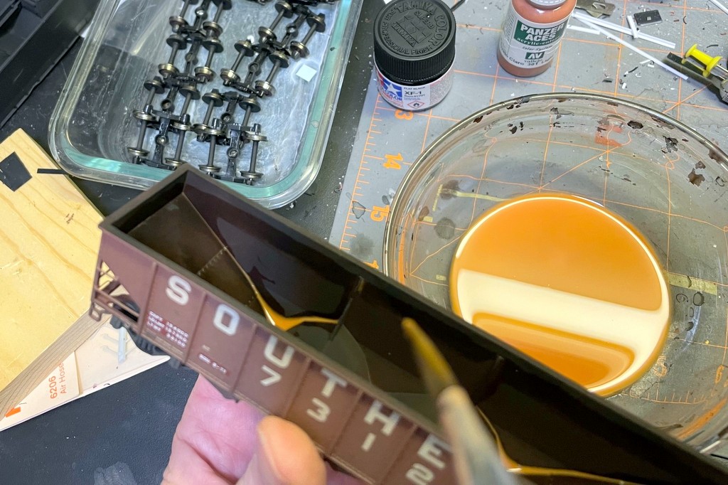
The interior rust is a couple layers of rust-colored wash
I had a lot of fun weathering these. Each first got a coat of matte lacquer spray to help blend in the decals and to give the cars a nice finish for the weathering to stick to. Next, I dry brushed some black, light rust, and dark rust onto the sides of the older black cars to simulate fading paint, scrapes, and rust patches. Some of the red cars also got a few nicks of dark rust. I masked off the capacity data and shop dates of a couple of the cars to keep it new looking like a patch job. I airbrushed all the cars with a light coat of dark tan on the sides and underframe and some flat black inside the hopper. I sprayed the black thinly letting the red still show through a bit. The undersides got a little black as well to add to the grime. Next I gave each a wash or two of flat black to bring out some of the detail and add some grunge. The last step was the hopper interior rust. I made a wash of light rust color, painted a “water line” just below the top chord where the coal would reach, and filled in everything below with the wash. I sopped up any excess with a paper towel. Each car got 2-4 coats leaving some more rusty than others. A few of the older cars (like the black ones) got some extra dabbing of light rust on the insides and a little dry brushed dark rust for some variety.
The CofGa hopper got the most weathering of the bunch
Overall I’m happy with how these turned out, and I like this technique for weathering the inside of older hoppers. While newer hoppers tend to have lighter rust or even bare shiny metal, an older steel hopper tends to settle into a mottled dark rust color which I think the repeated light rust washes over flat black airbrushing accomplish pretty simply and convincingly.
Here’s an Atlas hopper before touch-up painting and weathering showing the additional details and “grab shaving”
The hoppers all got medium weathering and old rusty interiors suitable for their represented age
70T hoper 281260, assigned to the CNO&TP, shows off its dark rusty interior
The only 70T hopper in older roman lettering is 281056–renumbered to fit into a CNO&TP series of these cars
The “oldest” hoppers in the group are a pair of war emergency rebuilds still in original black and a “heritage hopper” Central of Georgia hopper in original colors
A few of the cars with some coal loads showing the heaps straight from the tipple
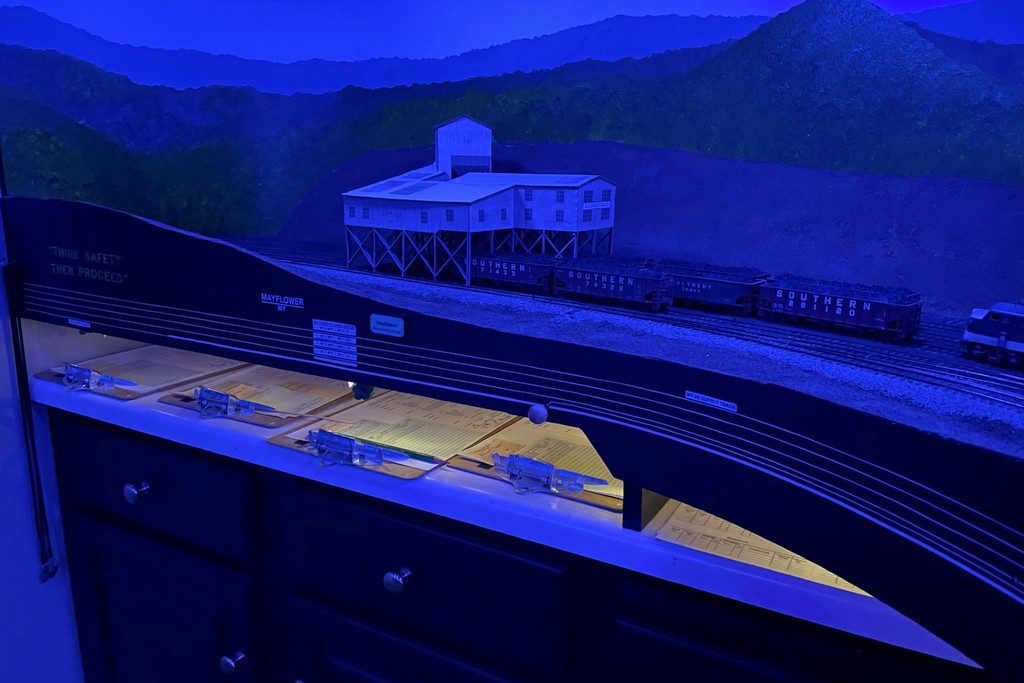
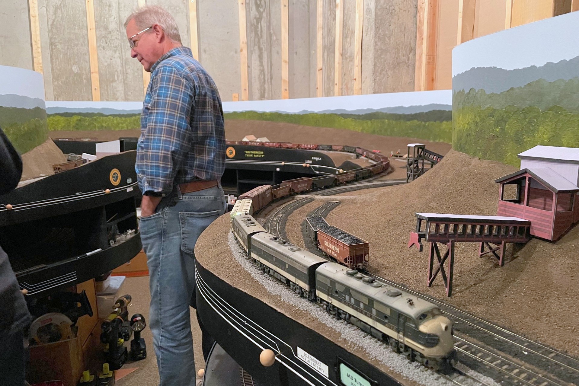
Engineer Patrick runs an L&N RS3 around its cars to spot empties at the Mayflower tipple as conductor Rick checks the switch list
Last night marked another successful operating session on the St Charles Branch–the first with the scenery base in place and perhaps the last lower-deck only session. We ran a full 1968 session with three trains, all led by aging first-gen power. First up was the L&N’s CV Local with Patrick at the controls and Rick making his debut as a conductor. A pair of loads picked up at the trailing point operation at Maness (off the layout) gave the crew a little extra to work around all shift. While the CV Local was up the Bailey’s Creek Branch, I ran Southern Train 61, brining in a couple dozen empties from Andover and picking up last night’s loads from the tiny yard at St Charles. For the first time, train 61 was led by a trio of grungy F-units.
Southern’s Train 61 shoves a string of empties past the JAD Turner loader in St Charles
After waiting a bit for the slower-than-normal work of train 61 to finish up in St Charles, the CV Local tied up in Pennington staging before Patrick and Rick fired up the pair of local F-units for the Southern’s St Charles Switcher. Blocking their train in the yard, the crew set out to work four loaders including the two new stand-in mock-ups in St Charles. The job took 8 fast-clock hours to complete due to all four operations being stub-ended and requiring run-arounds and removal of loads before spotting empties–’twas the lot of those who worked this line!
The St Charles Switcher completes a run-around at Mayflower with Rick at the controls
“Firsts” and experiments for this session
First session with zero derailments from poor track or cars (we did have an operator-induced derailment, but I won’t say who…)
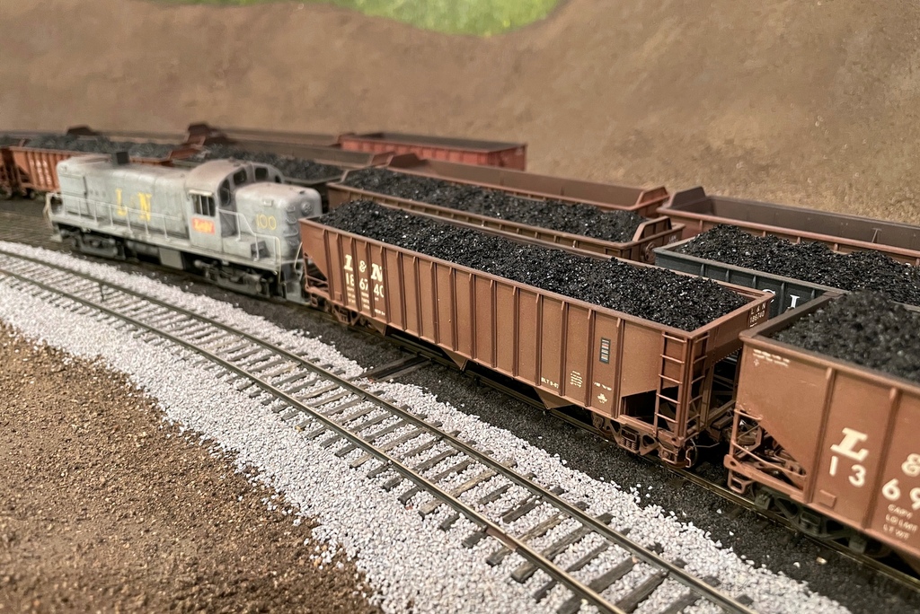
Here are several of the finished coal loads waiting to head back to the L&N
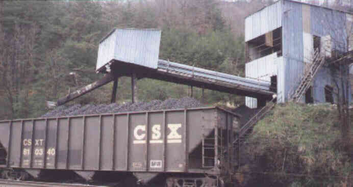
After years of hauling around black foam core inserts pretending to be coal loads, I finally got around to finishing some of them… 58 to be precise! I won’t go over the whole process here (article coming soon on Appalachian Railroad Modeling), but I’ll give you the basics here. Most people are used to seeing gently sloping coal loads that can barely be seen over the top of the car–this is a load that’s been on the road for a while and settled into the car. I model coal at the source, and this looks very different. In the ’60s and ’70s, much of the coal was loaded by feeding a car under a chute a few feet at a time using gravity or a winch to pull the car along in stages. This resulted in a series of high, distinct, and often uneven coal lumps, perhaps a dozen or more.
This hopper shows off the distinctive lumps of freshly loaded coal from a tipple that moves the car a little at a time. Triangle Dock, Elkhorn City, Bob Helm photo
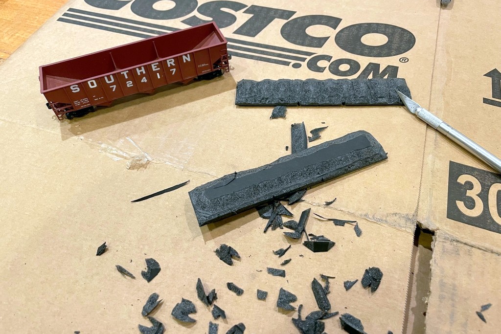
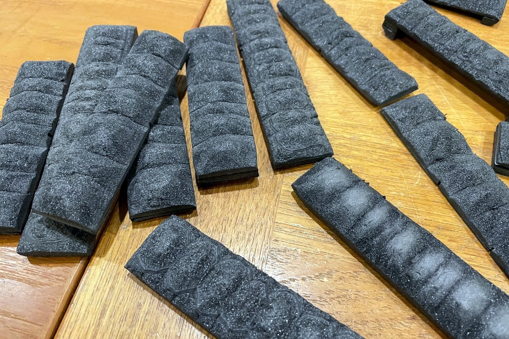
I haven’t seen too many modelers attempt this look, so years ago (like 25 years ago), I came up with a way to model this look using foam core and real coal. 25 years later, the biggest improvement has been the introduction of black foam core which does a MUCH better job of hiding any imperfections. I use 1/2″ black foam core, though some of the older forms were made from two 1/4″ pieces laminated with white glue. I basically cut them about 1/16″ smaller than the dimensions of the hopper, press them into the car to know where to cut notches for any bracing, and carve the load. I start by cutting a rough 45-degree angle around all sides, then I cut notches where I want the lumps to be. I try not to be too precise, and all the lumps are slightly different sizes. I then start rounding the lumps and eventually cut the top poster board layer off the foam core. The final shaping is done by compressing some of the foam with my fingers to smooth it out. If it needs it, I’ll add little pieces on the ends underneath and cut them to fit the car so the load sits a little higher.
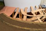
The loads start with 1/2″ black foam core cut slightly smaller than the hopper and carved with an X-Acto bladeSeveral load forms ready for coal–each one is unique
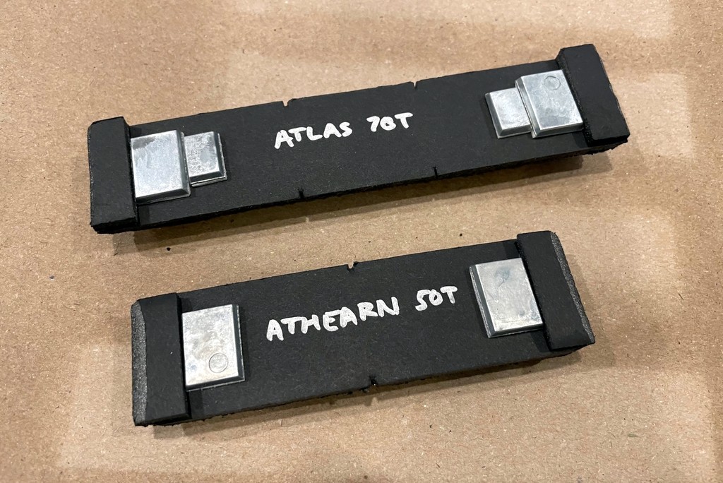
Before I lose track, I label each load for the type of car it fits (easy with a silver Sharpie), and I add a couple of stick-on weights under each load (pinewood derby weights). I want my coal cars to “feel” heavier to a locomotive when they’re loaded, and I also want them to be a little top heavy like the prototype so crews will handle them a little differently.
Once it’s cut to shape, I label each load and I add some stick on weights. This picture also shows the notches carved in for the braces
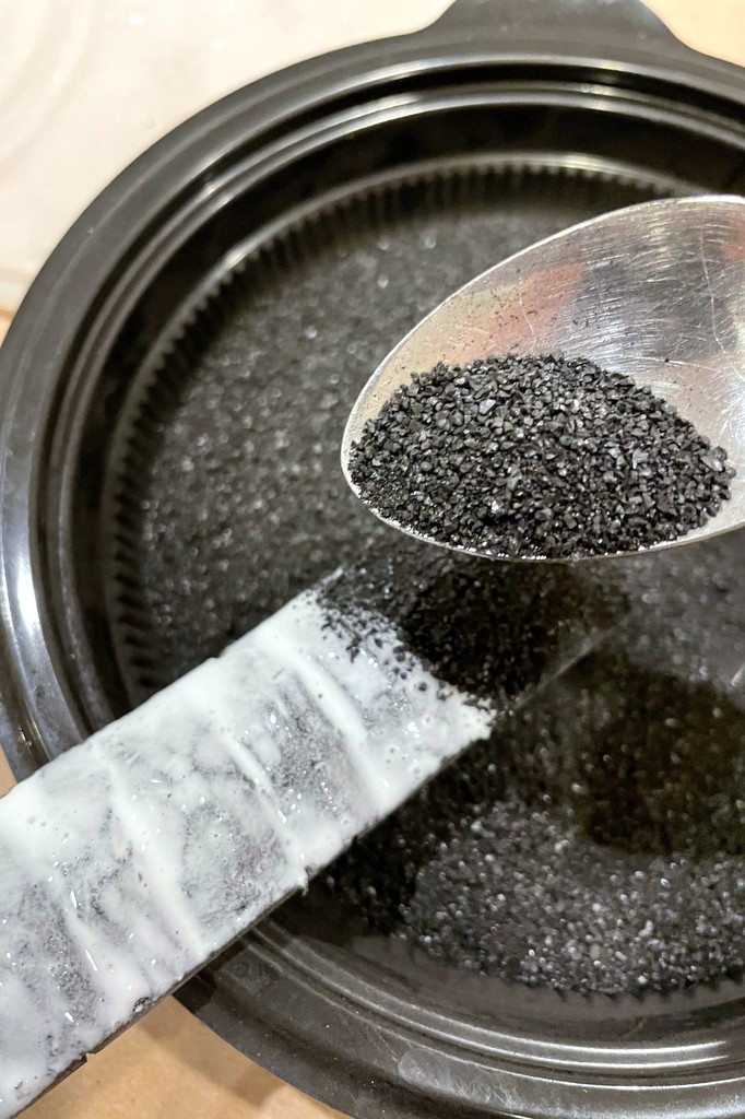
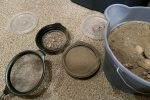
I grind my coal the old fashioned way: with the butt of a butter knife in an old Cool Whip container. Then I sift it with a kitchen strainer to get a container of small coal. I paint the top of the foam core with straight white glue, then sprinkle the coal over the top and shake off any excess. I do this over the coal container so I can recycle any coal that falls off.
The coal is real coal, ground up with the butt of a butter knife and sifted with a sieve before being added on top of a coat of straight white glue
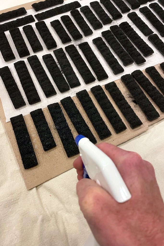
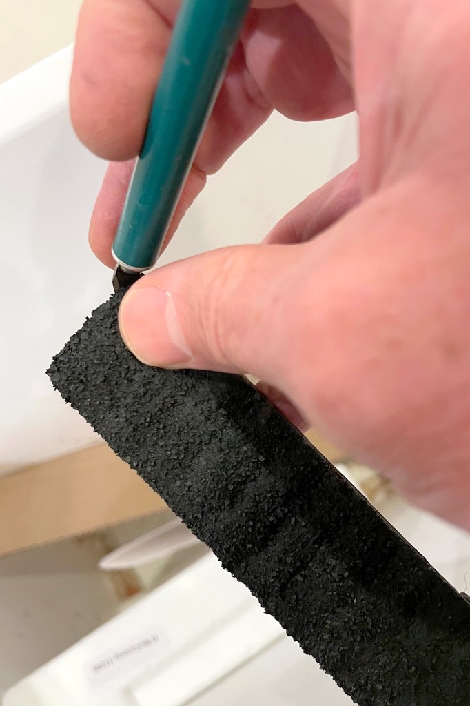
I set the loads on parchment paper to dry overnight. The next day, I spray the tops of the loads with “wet glue” (about 8:1 water:glue + a couple drops of dishwashing soap) until they’re saturated. This really sets the loads and keeps the coal from leaving dust on hands and models. Once the glue has completely dried, I go along each load with my fingers, knocking off any protruding pieces of coal, then I clean up any coal on the edges with an X-Acto blade.
After letting the coal loads dry overnight, I hit them with “wet glue” to further set them and to keep the coal dust from rubbing offOnce the wet glue is dry, I clean them up a little with a finger to knock off any pieces sticking up too high and an X-Acto blade to clean up any coal pieces on the sides
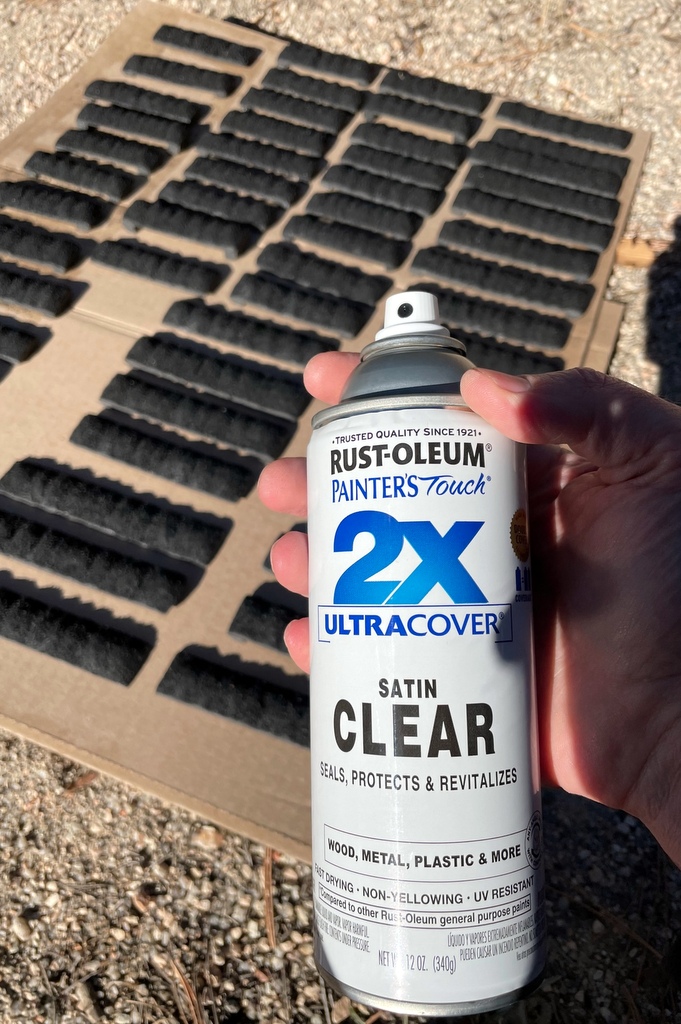
The white glue tends to dull the coal’s sheen, so my last step is to hit the loads with a coat of clear satin-finish lacquer spray–this looks about right to my eye to bring the coal back to its original luster. All told, when you do them in bulk, it only takes a few minutes and a few cents worth of materials per load, and I love the way they look! I also like that each load is absolutely unique–something tougher to achieve with commercial loads.
The white glue dulls the coal a bit, so the last step is to restore a bit of the sheen with some clear satin finish lacquer sprayThese removable coal loads capture the distinctive lumps of freshly loaded coal piled high
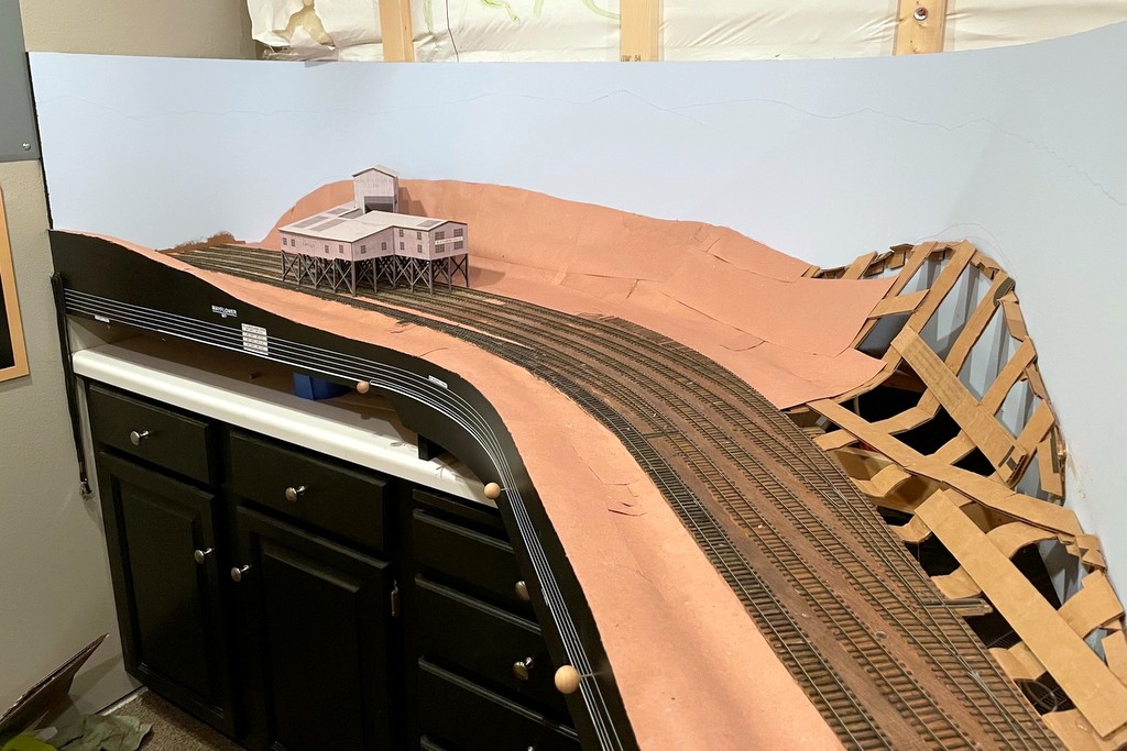
Yesterday marked the fourth anniversary of the first piece of benchwork for the St. Charles Branch. I’m certainly not moving at any blistering pace, but it’s fun to look back and see the progress! Here’s a look at how one corner of the layout has progressed over those years. Mayflower is at the end of the Bailey’s Creek Branch and is the largest loader on the lower deck. I really like how the scene is shaping up!
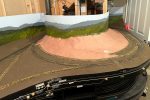
Here’s the first piece of benchwork installed for the staging area under Mayflower on October 26th, 2019.
The next year was lockdown year, so by October 2020 the staging level was complete and the DCC system was up-and-running. I finished the last piece of the lower-level benchwork with this final piece that would ultimately support the scene at Mayflower.
By the middle of 2021, I was making good progress on the handlaid track. The track at Mayflower was the first to be completed, and by October of 2023, I had run up the helix from staging and was on my way to connecting the line from St Charles to Mayflower by the end of the year.
2022 was a productive year, and by October, I had finished the fascia, installed the backdrops, and was working on the scenery base. Mayflower was the first area to get its “paper shell” covering.
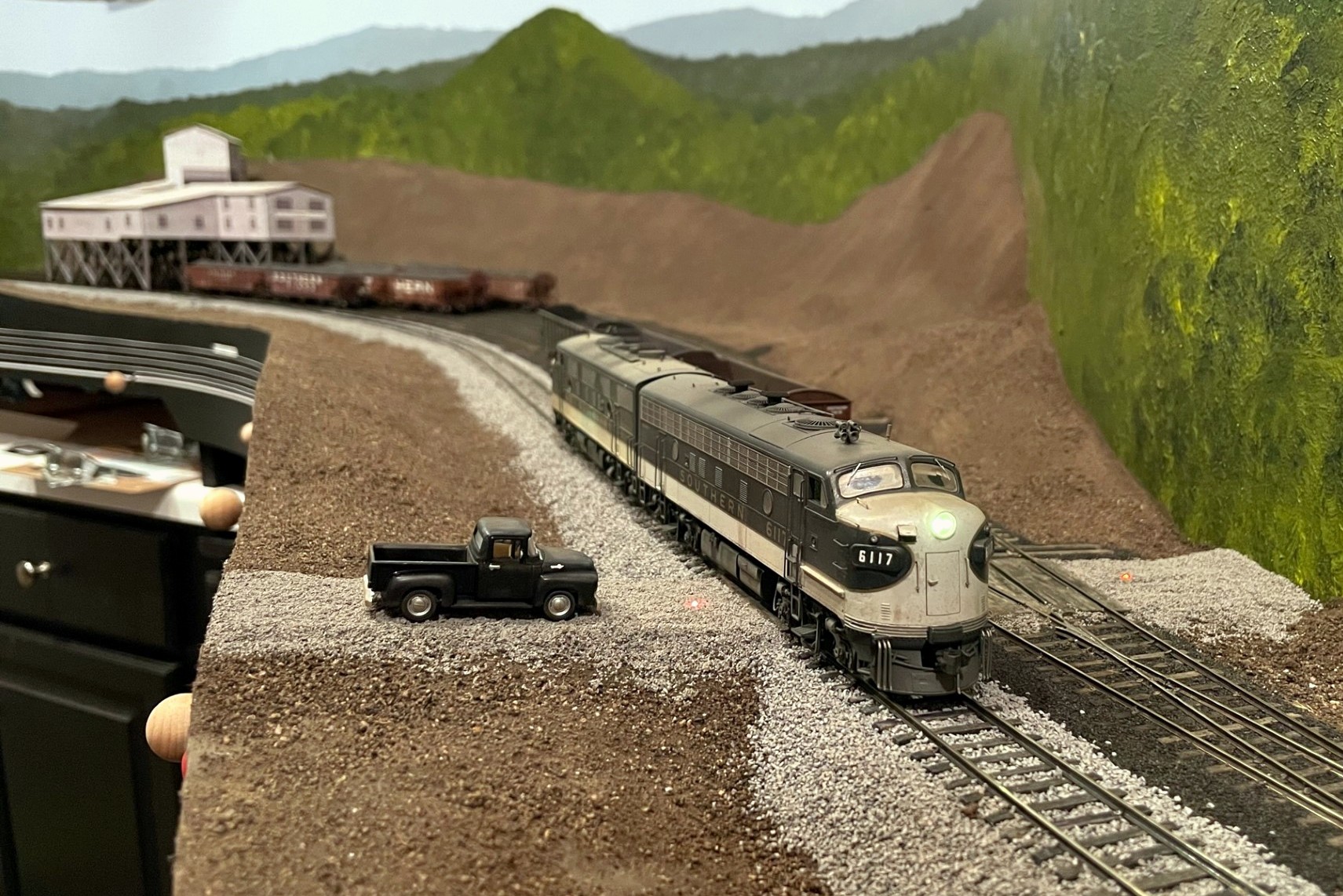
Here’s the scene at Mayflower today in 2023. Vegetation is still sparse, but in the past year, I’ve learned how to paint backdrops, finish the scenery base, and ballast track. I’ve also added some fun features like working crossing signals for major grade crossings and fusees for smaller grade crossings like this one at Potts Branch Road. It’s getting there!
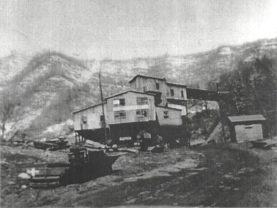
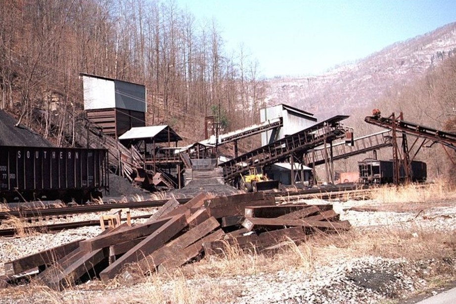
For comparison, here’s a view of the prototype scene at Mayflower as it awaited the scrapper’s torch (photographer unknown).
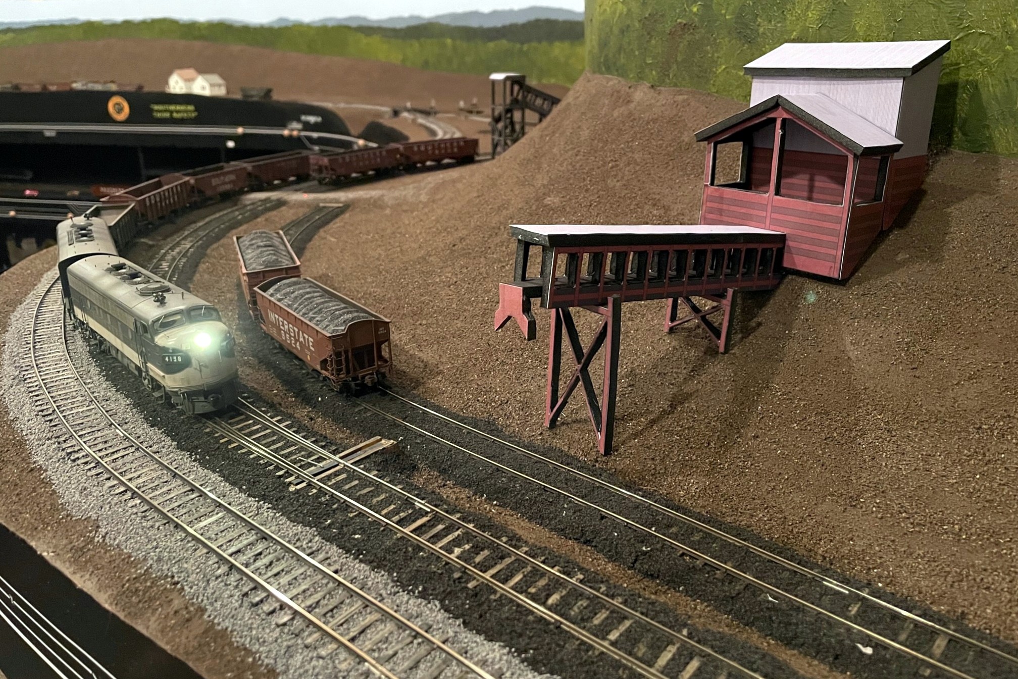
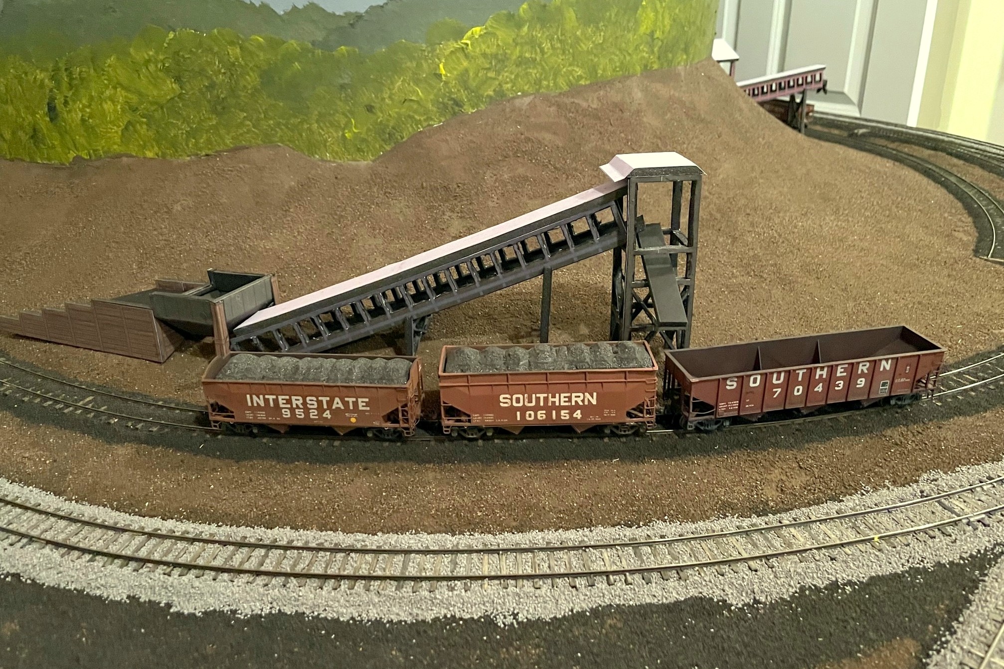
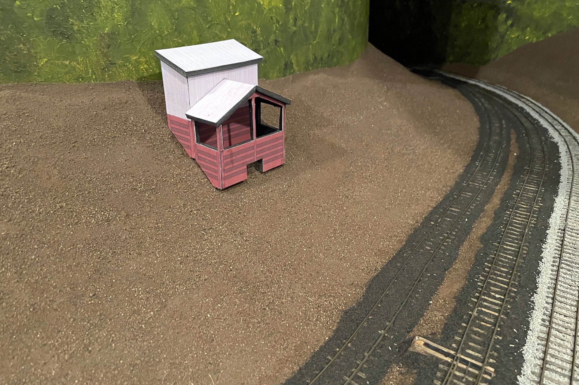
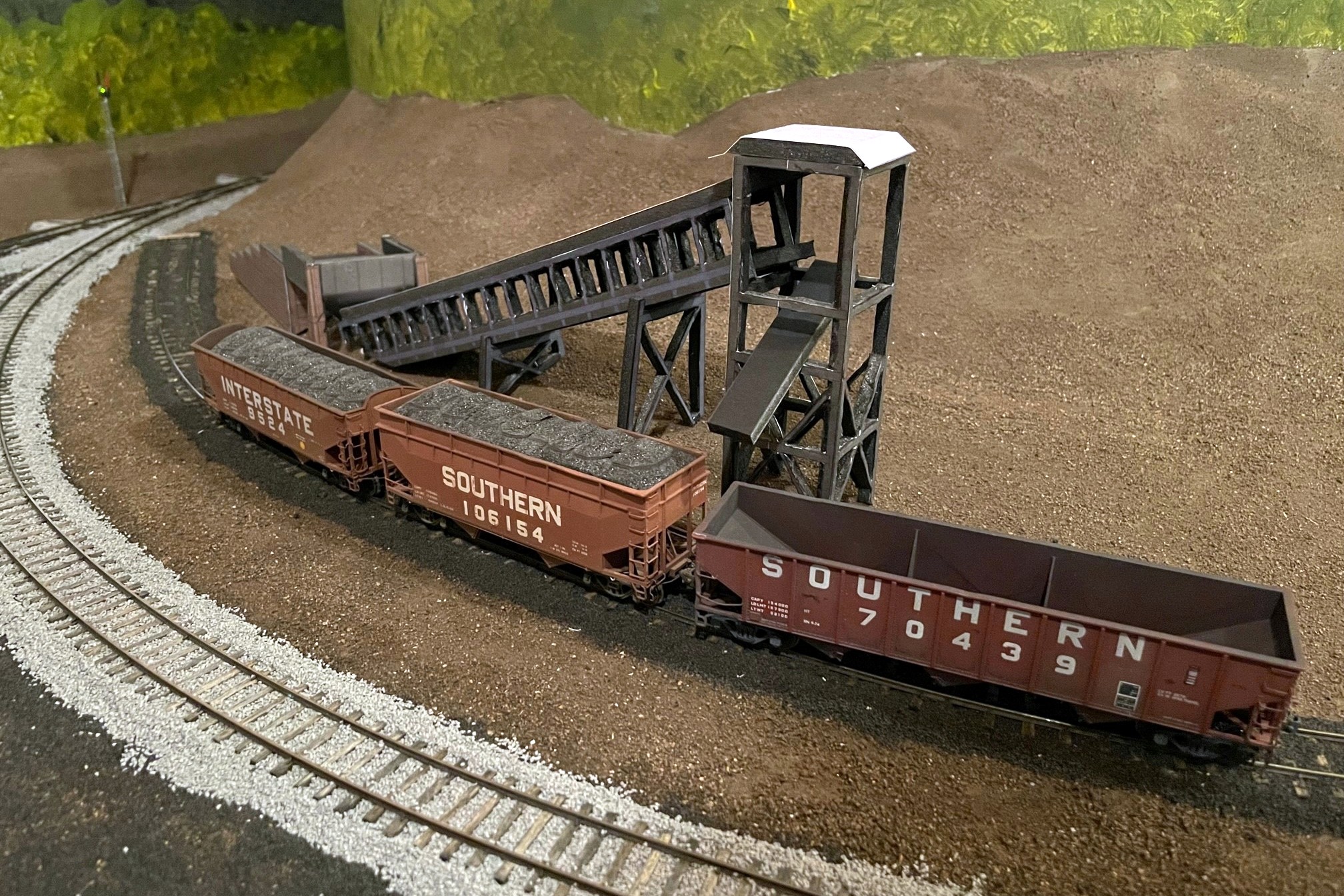
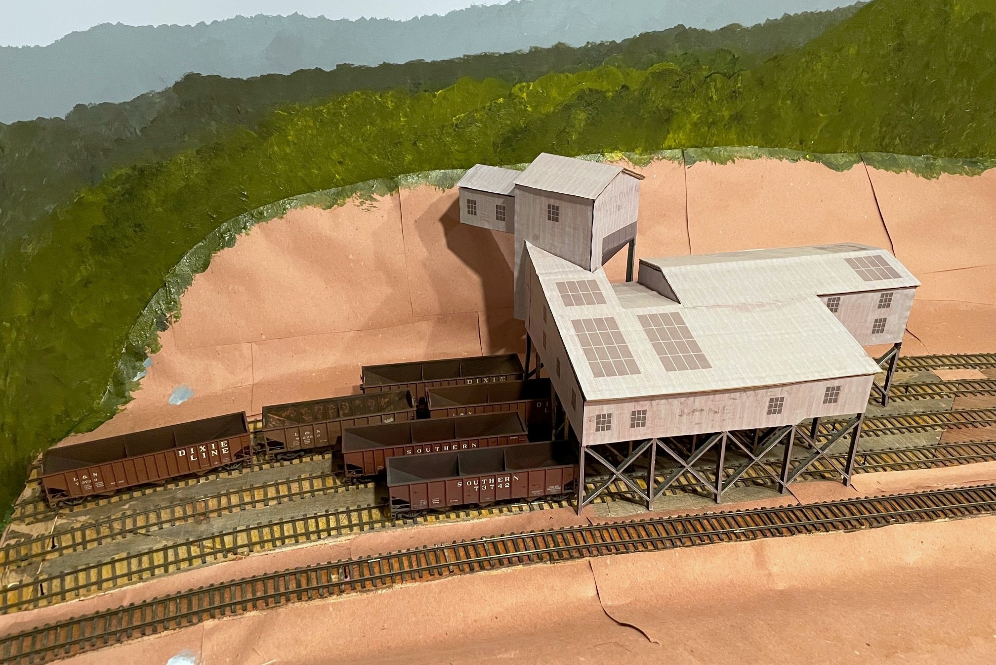
Here’s the full mocked-up scene with the St Charles Switcher preparing to swap empties for loads at the JAD Turner loader–the St Charles loader can be seen just around the hillside
As I’ve discussed previously, I like to build mock-ups out of foam core and paper of the larger structures on the layout that I will eventually scratchbuild. This serves three purposes. First, it gives me an opportunity to create a line-drawing / blueprint and make sure the drawing works before cutting more expensive materials. Second, it allows me to visualize a scene and make adjustments before I build the permanent structure. And third, it gives me a good stand-in on the layout until I can build the real one–something that makes operations a lot more fun than imagining there’s a big structure where you’re switching! For this third reason, I put a little extra effort into the drawings to give them some color and texture. I’ve covered the techniques before, so I won’t repeat them here.
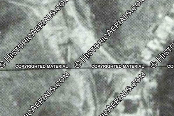
This project involved the two “truck dump” tipples that were built in the late ’70s (as far as I can tell) near St Charles, VA. One is known as JAD Turner, and it’s probably still standing today. The other sat on the wye at St Charles for just a few years–I don’t know it’s name, so I’m just calling it the St Charles loader (super original, I know…). What made this project challenging is I didn’t have any good photos of the loader configuration I needed to model. JAD Turner was modified over the years with a second conveyor and second empty track, but the earliest photo I have of it (a grainy aerial from 1981) clearly shows only a single conveyor. I’m modeling it as if it’s the same tipple but with fewer added parts, so I took the dump shed / crusher section of the current loader along with a single conveyor and came up with this design that looks reasonably close to the aerial.
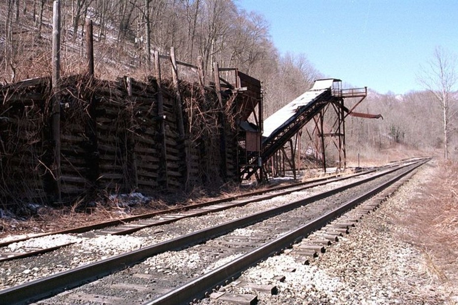
Here’s the JAD Turner loader near St Charles in the late ’90s with additional chutes added, but I modeled the core dump shed, crusher, and one of the conveyors (Robby Vaughn photo)Here’s the finished JAD Turner loader mock-up complete with a little double chute over the rails
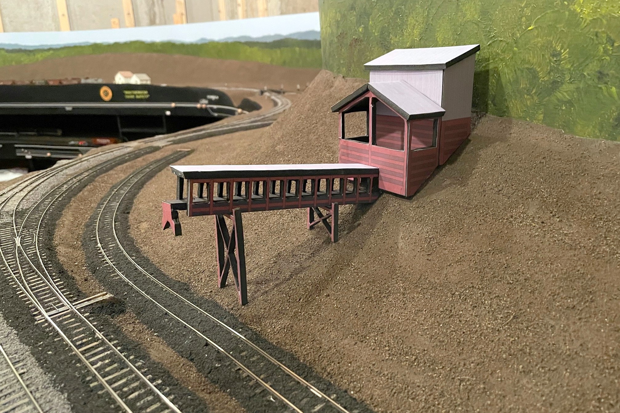
St Charles was a little more challenging as the ONLY photo I have is a grainy aerial from 1981 showing what looks like a pile of coal, a conveyor (maybe two), and what looks like a dump ramp but no shed. I didn’t have to look far to find something close. Just up the road between St Charles and Mayflower was a loader known as “Southwest” which had a similar dump and conveyor arrangement. Southwest was built after my era, so I won’t have to have two similar looking loaders on the layout. Who knows, perhaps they moved the loader from St Charles up to Southwest? That’s my story until someone proves otherwise…
The Southwest loader sat between St Charles and Mayflower but after my era–I’m using it as the prototype for my St Charles loader (Robby Vaughn photo)A view of the St Charles loader mock-up showing the ramp and dump area
Anyway, here are the results, and I’m really liking the scene now. I can’t wait to build the real things! But first the upper deck…
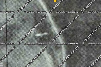
This grainy aerial photo from 1981 (courtesy of the awesome HistoricAerials.com website) clearly shows a single conveyor at the JAD Turner loadout, so I removed “extra” parts from the ’90s loadout to get my design
Here’s the JAD Turner loader near St Charles in the late ’90s with additional chutes added, but I modeled the core dump shed, crusher, and one of the conveyors (Robby Vaughn photo)
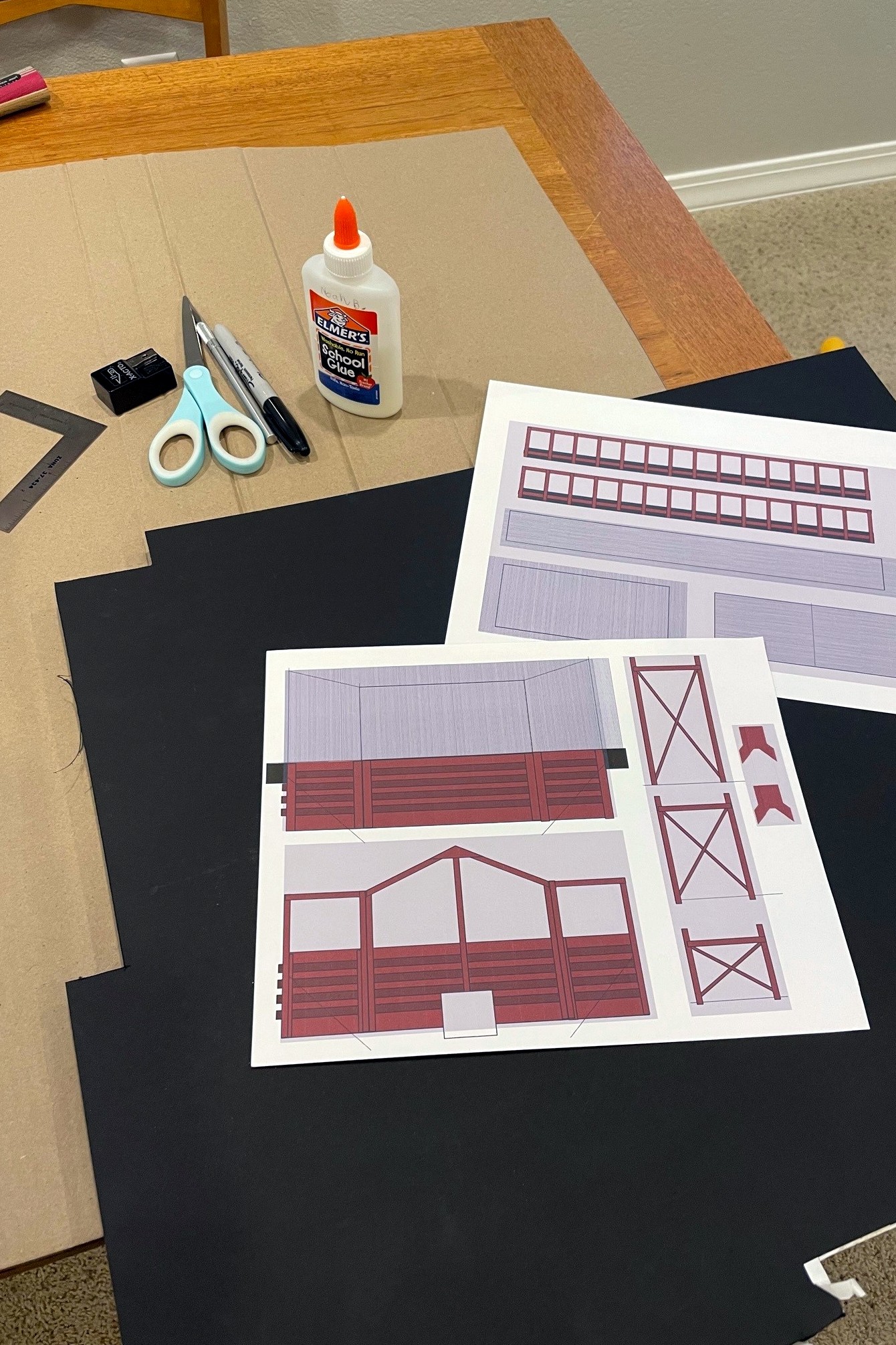
Here’s the drawings I did for a JAD Turner loader mock-up using MS PowerPoint along with the supplies needed to build the “paper doll” mock-up
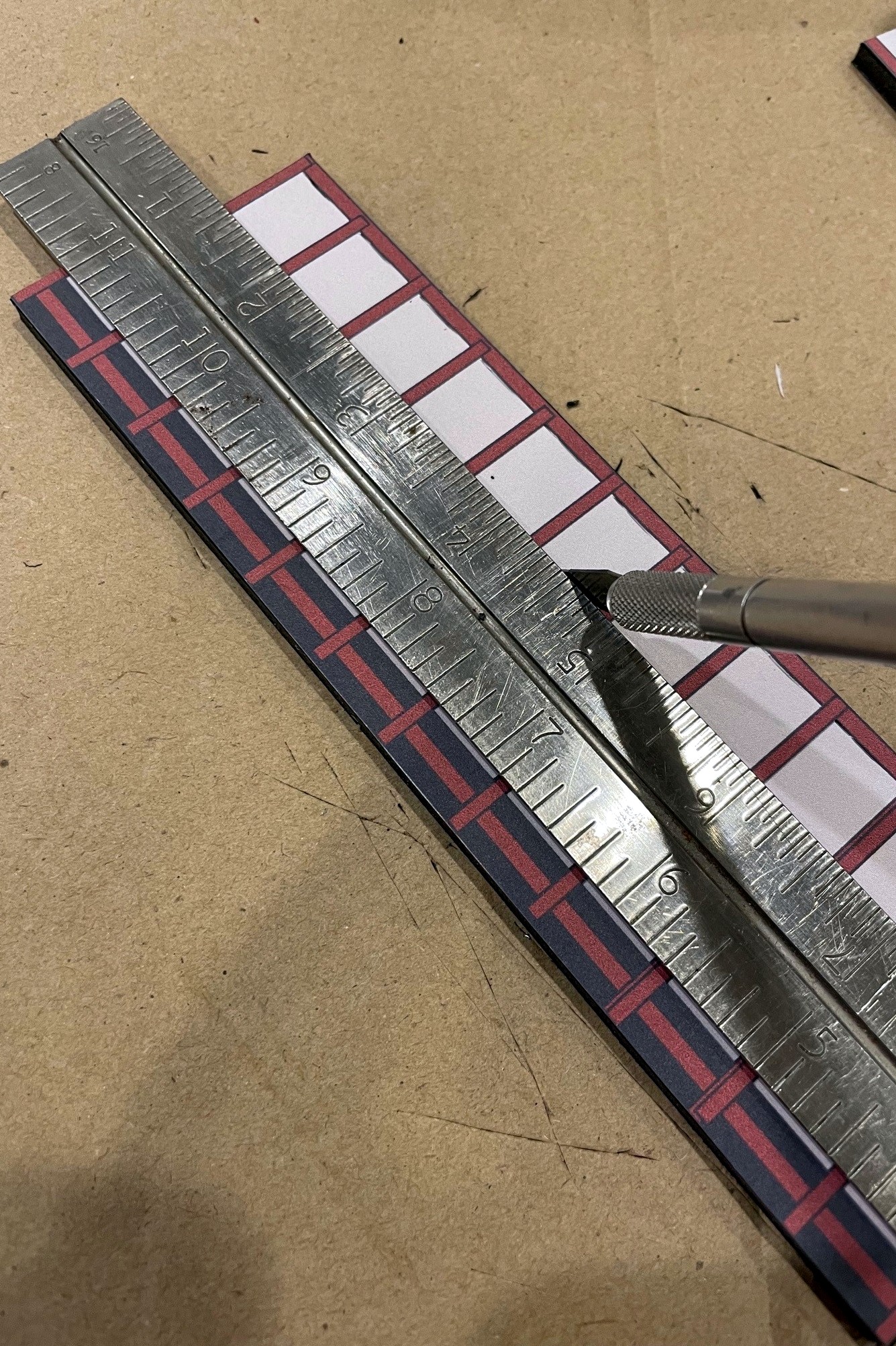
I used a sharp X-Acto blade to cut out the structure details for the conveyors and legs
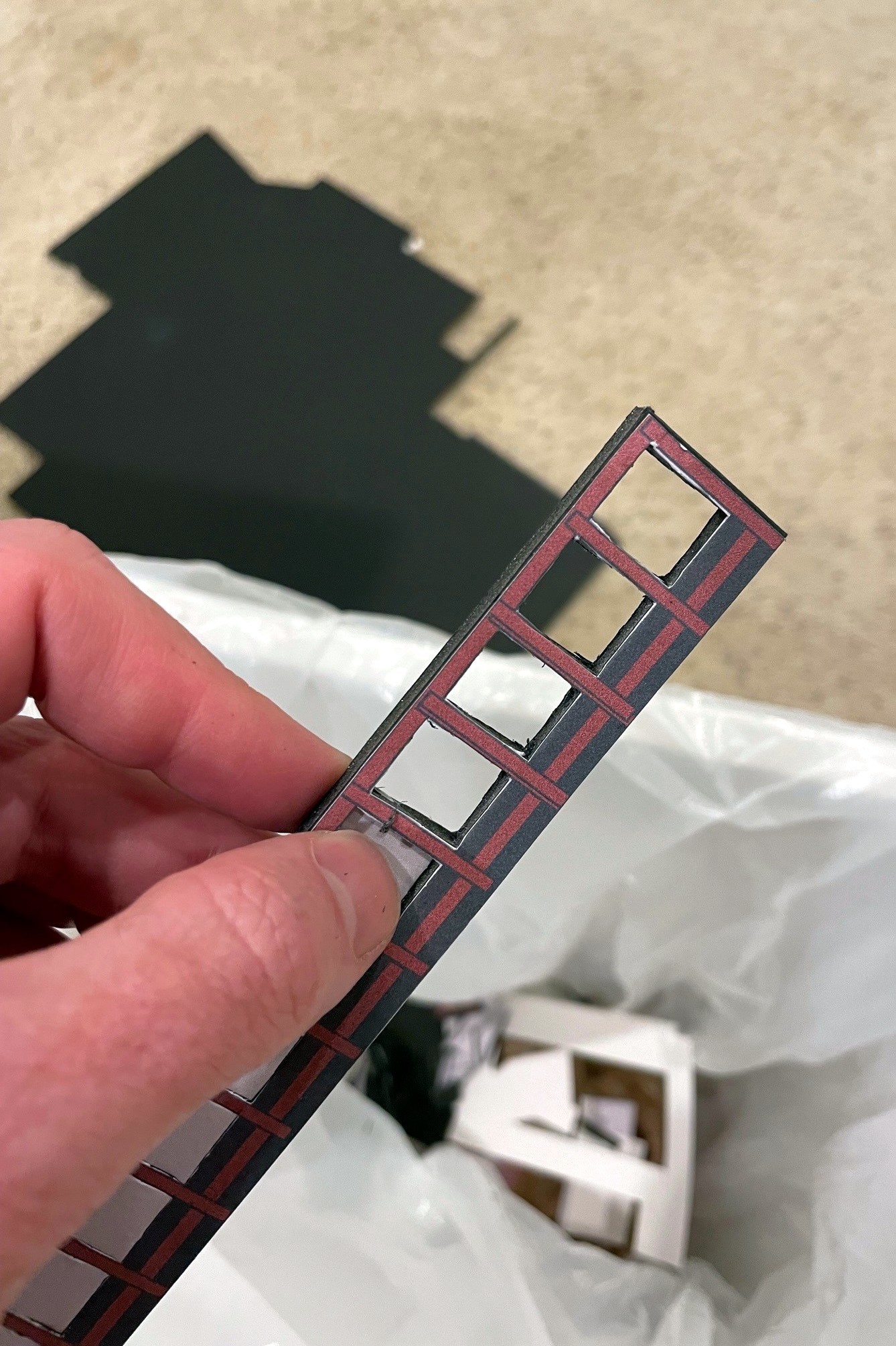
Once the area has been well scored front and back, it’s pretty easy to just pop it out of the foam core frame
Here’s my dump shed and crusher bin mock-up for JAD Turner. I used an X-Acto to fit it to the hillside
Here’s the finished JAD Turner loader mock-up complete with a little double chute over the rails
This grainy aerial view of the St Charles loader circa 1981 (courtesy of HistoricAerials.com… awesome website) is all I have from which to base my loader model
The Southwest loader sat between St Charles and Mayflower but after my era–I’m using it as the prototype for my St Charles loader (Robby Vaughn photo)
Here’s the finished mock-up for the St Charles loader in place along the wye
Another view of the St Charles loader mock-up showing the ramp and dump area
Here’s the full mocked-up scene with the St Charles Switcher preparing to swap empties for loads at the JAD Turner loader–the St Charles loader can be seen just around the hillside
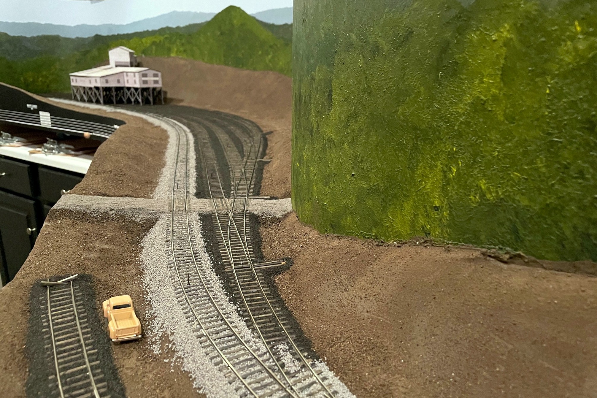
Here’s the St Charles wye with ballast. Note the area of cinders where a track used to be
While I finished the basic scenery forms on the lower deck a few weeks ago, I decided it would be better to ballast the tracks before adding the upper deck benchwork while I still had good access to them. I’m so glad I did because ballasting gives the scenes a much more “finished” look even though there’s still a ton of scenery work to be done. I’ll be honest, I was dreading ballasting the track–I had little experience with ballast, but from that experience I saw it as a frustrating, tedious, and time-consuming job. I have now changed my tune! While it’s still time-consuming, I was able to learn and mature my techniques quickly to avoid the frustration and tedium, so I’ll pass along my method here.
First, I had to determine what kind of ballast I needed. This wasn’t as straightforward as I’d hoped. As best I can tell, most of the tracks in my area were at one time ballasted in cinders harvested from steam locomotives. The steam locos went away in the 1950s, and with them the ability to get cheap and ready cinders for ballast. Photos from the ’80s and ’90s clearly indicate most everything got covered in rock ballast–would the cinders still be around in the 1960s and ’70s? After some digging online, I found that cinders in many places lasted for decades after steam, and in the coal fields, it’s tough to tell cinders from spilled coal anyway, so an added incentive for cinders, at least on sidings and secondary tracks. For the main tracks, photos show the Southern’s ballast in this area was a medium gray. I toyed around with trying to find some actual rock to use as ballast, but in the end I decided on good old Woodland Scenics products made from crushed walnut shells because I can find it readily, it doesn’t cost an arm and leg to ship, and it’s pretty easy to work with. I used fine cinders and medium sized gray ballast in the big shaker containers for this project, and I was able to do the entire lower deck (12′ x 16′) with just under two shakers of each color (4 shakers total).
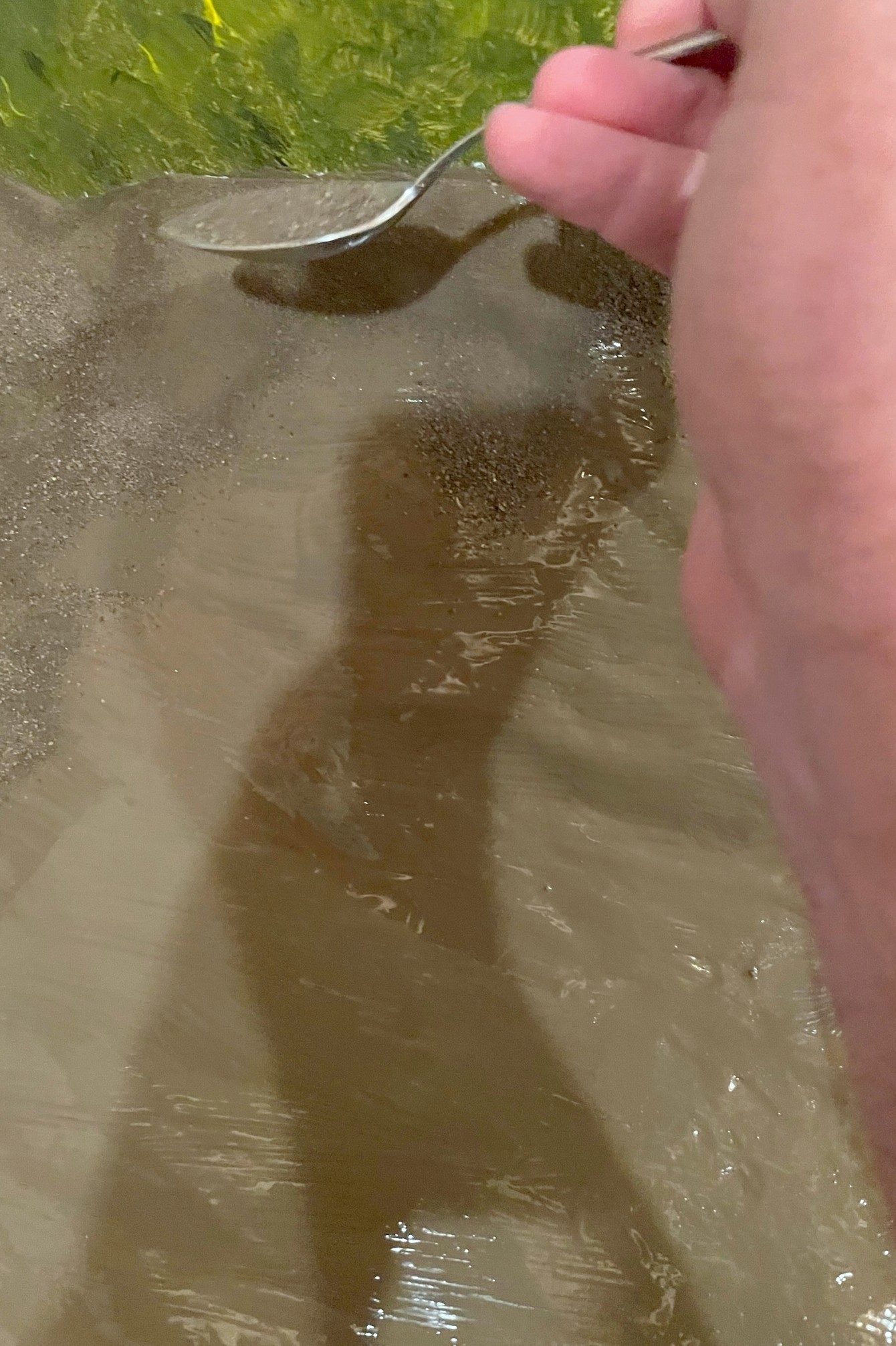
Second, I did a bunch of research on how to apply ballast, and I am so glad I did! In the end, I went mostly with the method Cody Grivno of Model Railroader lays out in the article here. The only other materials I needed were white glue (I bought a gallon), isopropyl alcohol (I used about XX oz), and dish soap. For tools, I used a spoon, a large flat brush, a white glue dispenser (like the ones kids use in school), two small jars with eyedroppers, a work glove, and my fingers. In the glue bottle, I mixed up some “just a bit wet glue” which is about 2 parts white glue, 1 part water, and a drop or two of dish soap–when you squirt it out, it should dissipate from its bead but not run. In one of the jars with an eyedropper, I made a mix of “very wet glue” of about 1 part glue, 6 parts water, and a drop or two of dish soap–it should look about the consistency of milk and absorb into the wet ballast (I’ll explain that in a minute) after a few seconds. You’ll need a LOT of the very wet glue, so you can either make a big batch or mix it on-demand when you run out (what I did… it was a lot of trips). The remaining jar and eyedropper are for the isopropyl alcohol.
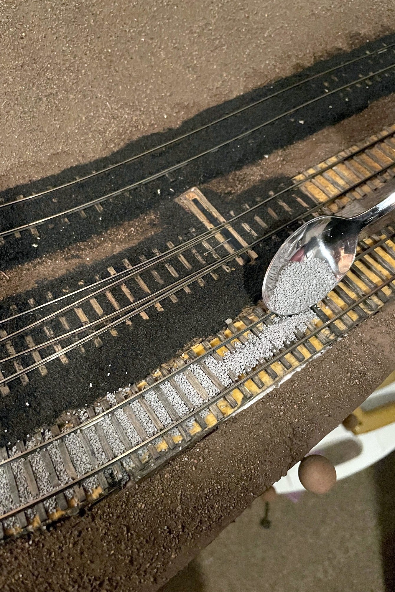
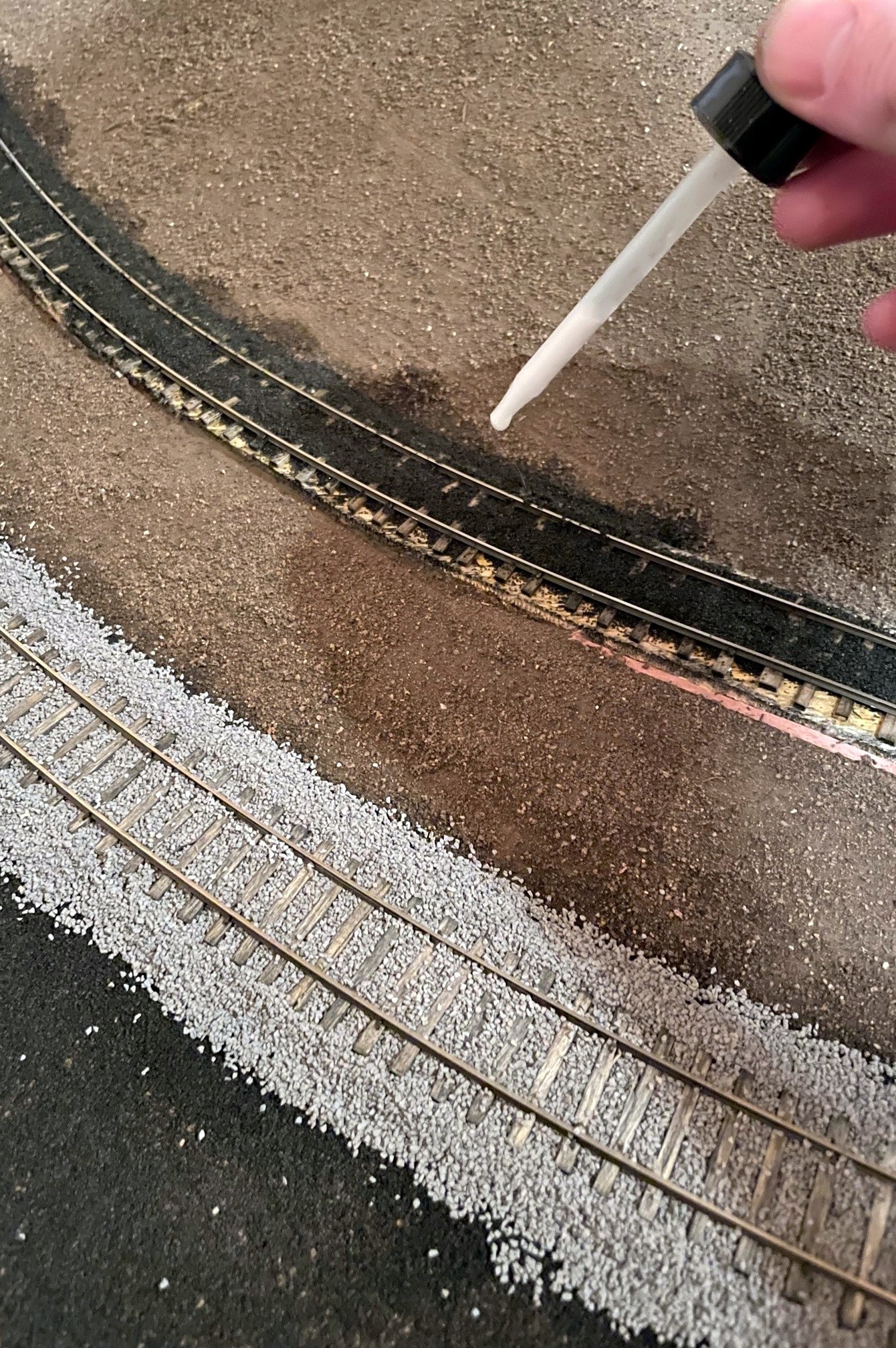
Step 1. Lay down a pile of ballast in the gauge between the railsStep 2. use a finger to spread the ballast between the ties, moving excess to the next section
I worked on the track in about 2 foot sections, usually one track at a time. If you’re doing two ballast colors, determine which ballast should be “lower” and work on that one first–for me, the cinders were replaced by ballast rock, so where they overlap, I did the cinders first. With about half-a-spoonful of ballast, I first apply it to the “gauge” (inside the rails) of the track. It takes a few tries to get a feel for how thick to lay it, but it becomes routine pretty quick. You want just enough that when you spread it the ballast fills the space in between the ties and rails with little on top of the ties and nothing on the rails. I found my finger to be an effective spreading tool, and I just rub it back and forth down the tracks, rubbing any excess ballast to open areas. Cody glues his ballast at this point, but I found it easier to lay the edge ballast first. I applied ballast to the edges by first running a bead of glue from the bottle down the side of the subroadbed and on top of the scenery–this helps the “slope” to hold better. Next I used the spoon to apply ballast inward toward the rail from about the edge of the ties until I couldn’t see the edge of the subroadbed any more. I used my finger again, first to poke the ballast under the rail a bit, then to wipe off the tops of the tie edges, and then to pat down the sloped edges until they looked smooth. I used a brush to clear off any unwanted ballast to outside the range of the glue (I vacuum it up later) and to remove any stubborn ballast from areas my finger couldn’t get to.
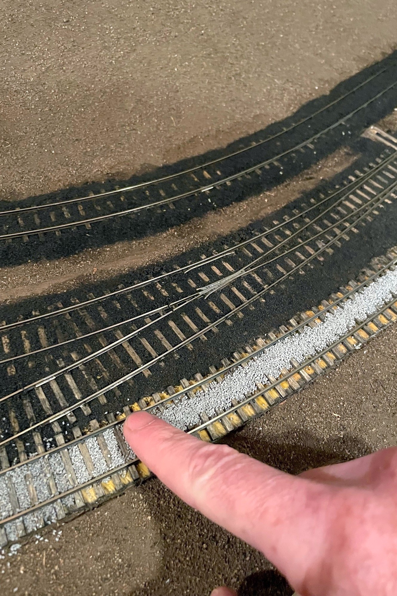
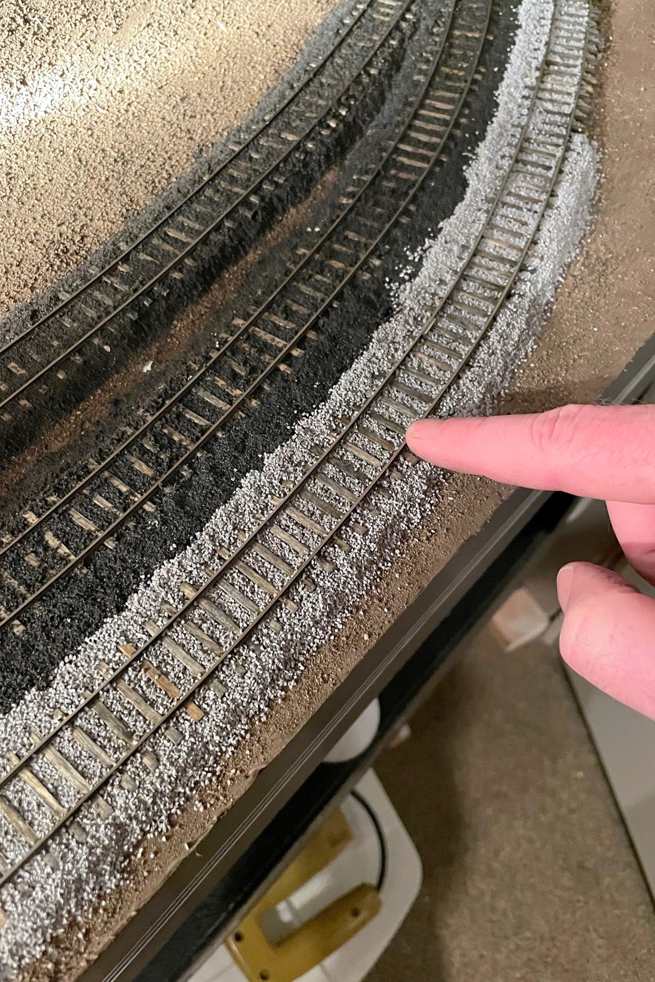
Step 3. Add ballast to the edges of the track, use a finger to work it into the ties, then use a finger to clean it off the ties and shape the slope
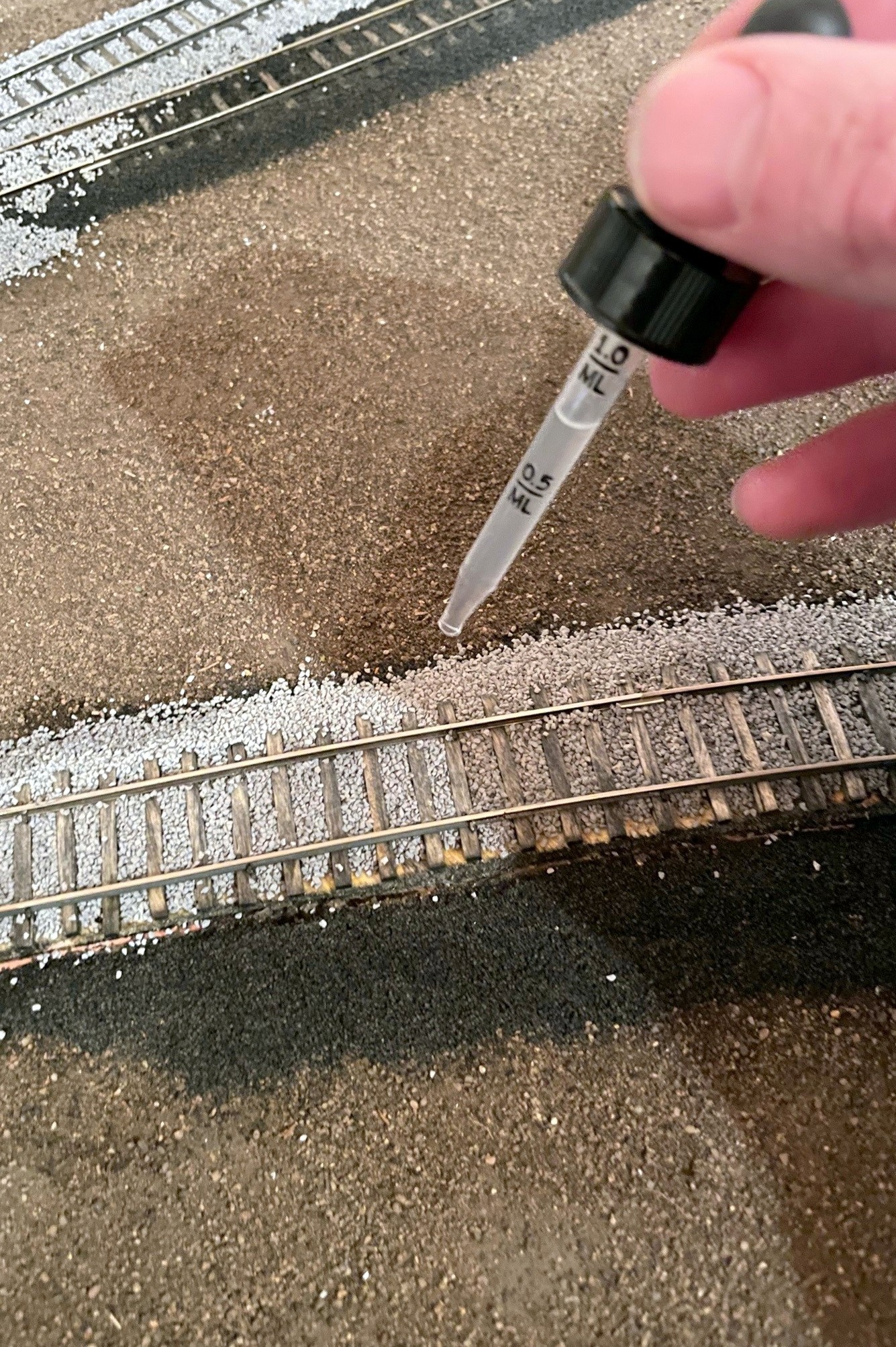
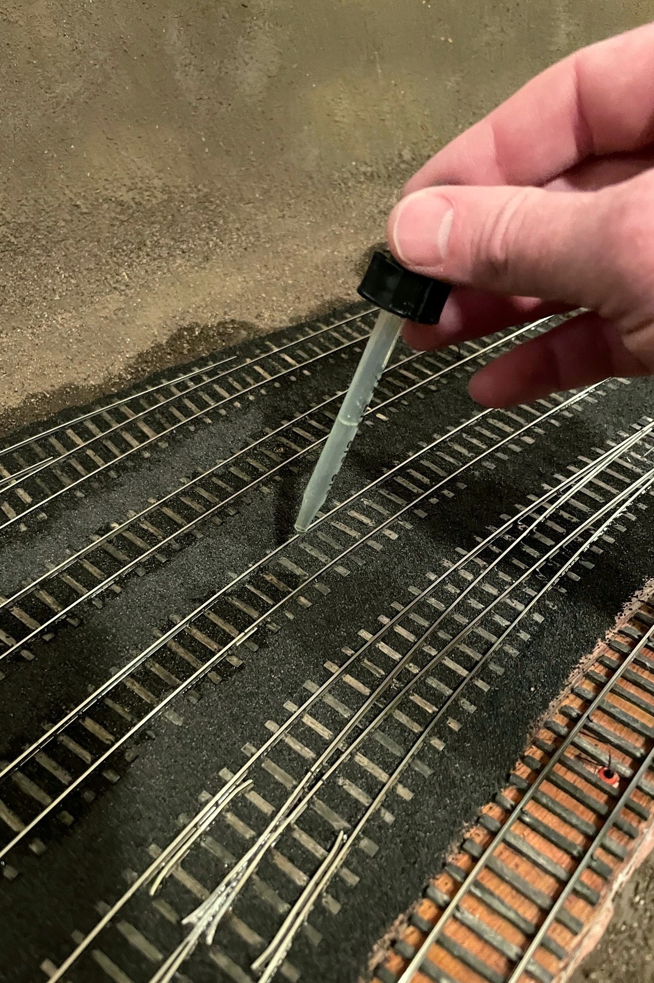
Once I’m happy with the ballast shape, I glue it down. The critical part of this process is to USE THE ALCOHOL AS A WETTING AGENT FIRST! If you just add the glue, the ballast will float (and float away) which makes a frustrating mess. You can avoid this by first saturating the ballast with an eyedropper of isopropyl alcohol–just drop until everything looks wet. I follow the alcohol wetting with the very wet glue, making sure I apply drops to every section of ballast until things were saturated and it took a couple seconds for the glue to soak in. If you drop a big glob of white glue that somehow didn’t get diluted, no worries–just dilute it with some alcohol, and it will likely settle in just fine. I wet and glued each section by starting with the gauge between the rails, then moving to the edges. I found for the edges it’s better to start the alcohol low and work up to keep things in place, and its better to start the glue high and let it work down.
Step 4. Using a dropper, soak the ballast with isopropyl alcoholStep 5. Saturate the wet areas with wet glue
Turnouts require a bit more care, and I probably didn’t take all the care I should have… it worked out ok, but I spent a couple hours massaging my turnouts to get them working smoothly again. I spread the ballast a little less thickly between the ties to make sure the points wouldn’t catch, and I took care to avoid putting ballast in the area of the throw. No matter how careful I was, there was always some piece determined to get stuck in the throw, so I used the brush (and the occasional X-Acto blade) to fish out any offenders. I used the very wet glue sparingly in these areas, but there was still some glue that stuck to the top of the ties causing the points to stick a bit. I believe Cody’s method is to drop the glue in first, then add the ballast under the points, and I think I’ll try this next time.
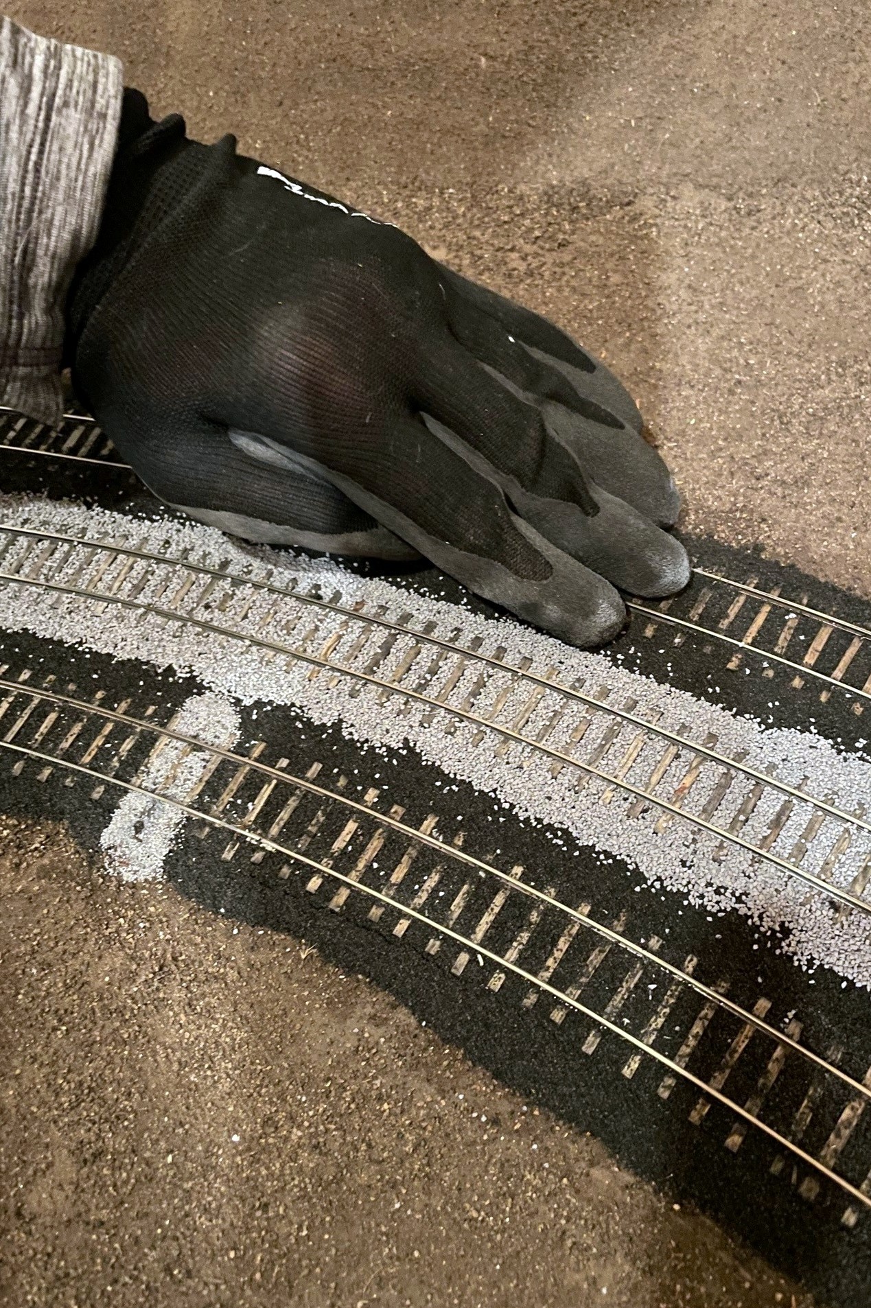
Step 6. Clean off any excess ballast–I use a work glove for thisStep 7. Clean any remaining ballast from the web of the rail–I use a combination of a matchstick and fingernails
After letting the glue dry overnight, I clean up any excess ballast. First, I use a work glove and rub it over the top of the ties and edges to knock off any obtrusive pieces. Next, I clean out the area in the web (sides) of the rail using a matchstick rubbed back-and-forth followed by a fingernail. I used a flathead screwdriver to clean out flangeways if necessary. I cleaned up any excess with a vacuum. You’ll inevitably find spots you missed with the glue, but it’s easy to just add more ballast, drop some alcohol, then drop some glue to repair.
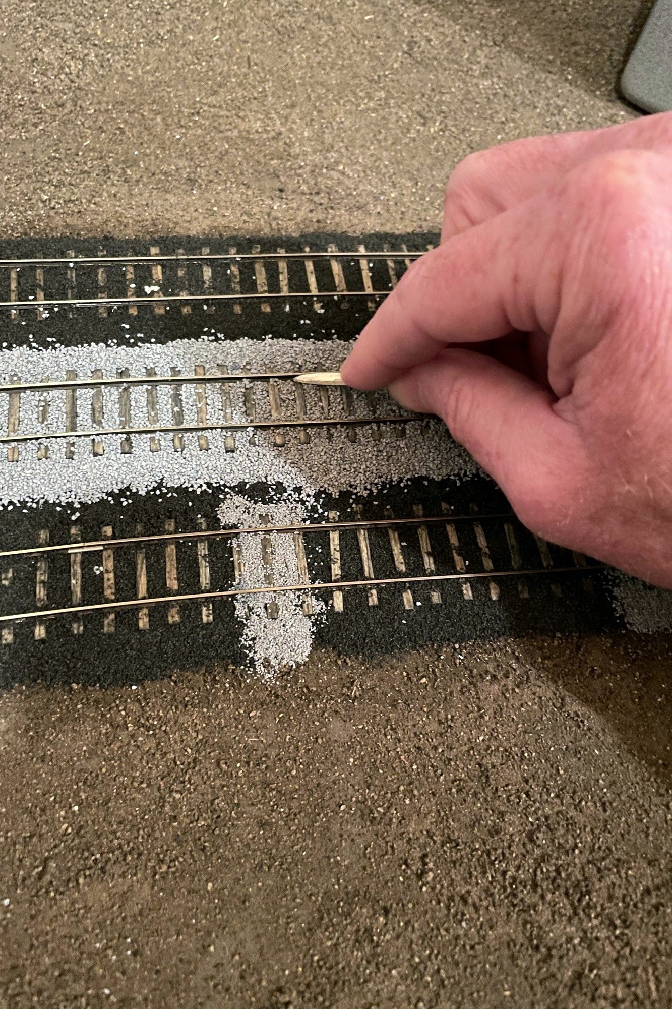
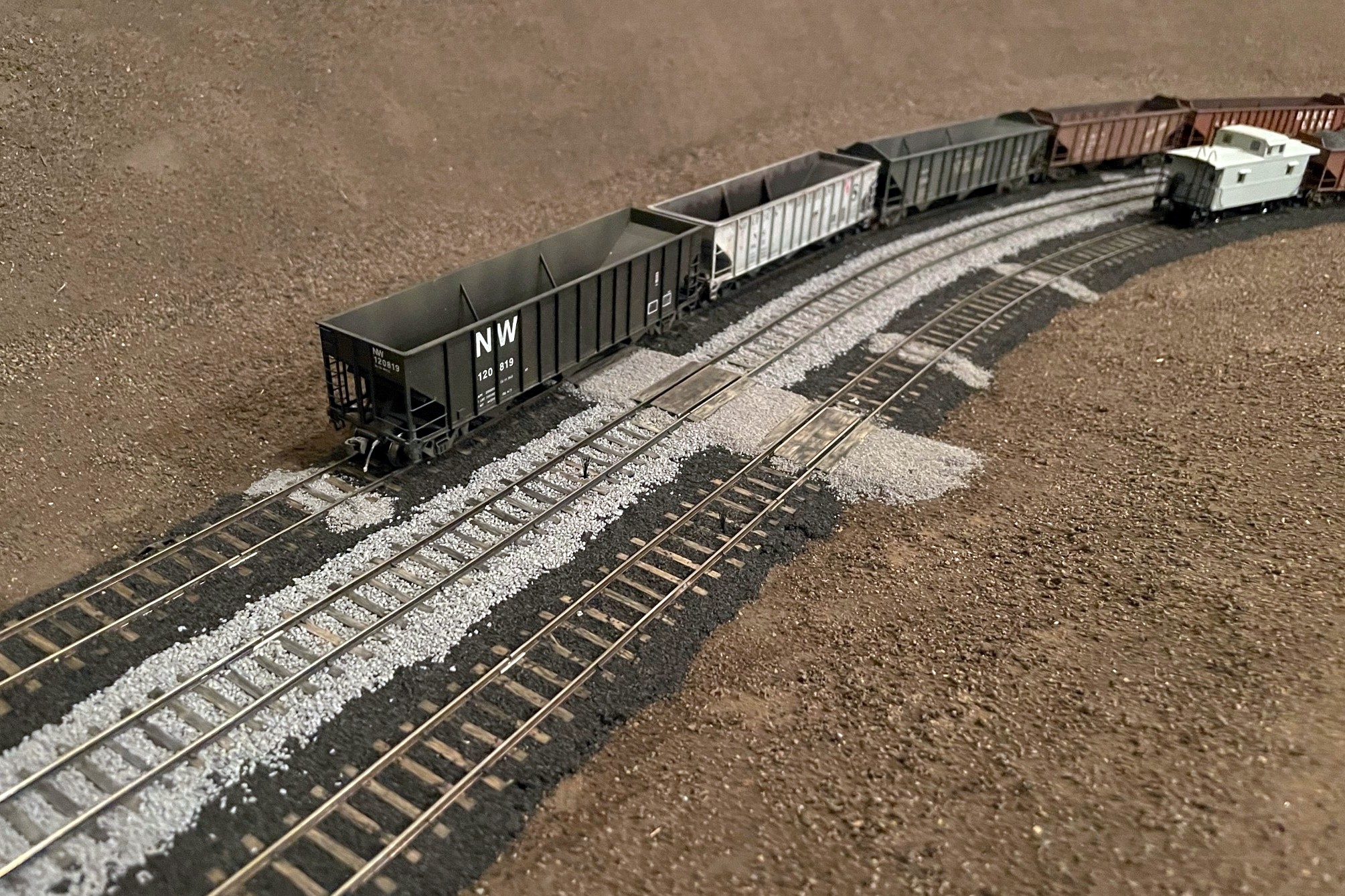
Ballast is scenery, so I also wanted it to tell a story. Because track repairs would have been made with gravel instead of cinders in my era, I picked a few spots along the cinder-ballasted yard tracks to fill with gravel (in this case, Woodland Scenics fine gray ballast) to simulate a replaced tie. I like the look! I also picked a few spots in prominent areas to lay some cinders on the scenery to go underneath the ballast rocks to show that some tracks were once cinders but had now been ballasted with rock. I also laid a thin layer of cinders in areas where I know tracks used to be, even though I don’t model them in my era. Finally, I added extra cinders to areas under tipple chutes and where locomotives sit to represent spilled coal and grime. I’m pretty happy with how these “extras” turned out, but they won’t fully tell the story until more scenery is complete.
The St Charles yard where the main is clearly visible. The gray areas on top of cinders represent tie repairs after the age of cinders
Ok, the ballasting was the last step before adding the upper deck, but you’ve heard that before… We shall see.
Here’s the finished ballast at the Mayflower tipple–the road is made from fine ballast as well
Step 1. Lay down a pile of ballast in the gauge between the rails
Step 2. use a finger to spread the ballast between the ties, moving excess to the next section
Step 3. Add ballast to the edges of the track, use a finger to work it into the ties, then use a finger to clean it off the ties and shape the slope
Step 4. Using a dropper, soak the ballast with isopropyl alcohol
Step 5. Saturate the wet areas with wet glue
Step 6. Clean off any excess ballast–I use a work glove for this
Step 7. Clean any remaining ballast from the web of the rail–I use a combination of a matchstick and fingernails
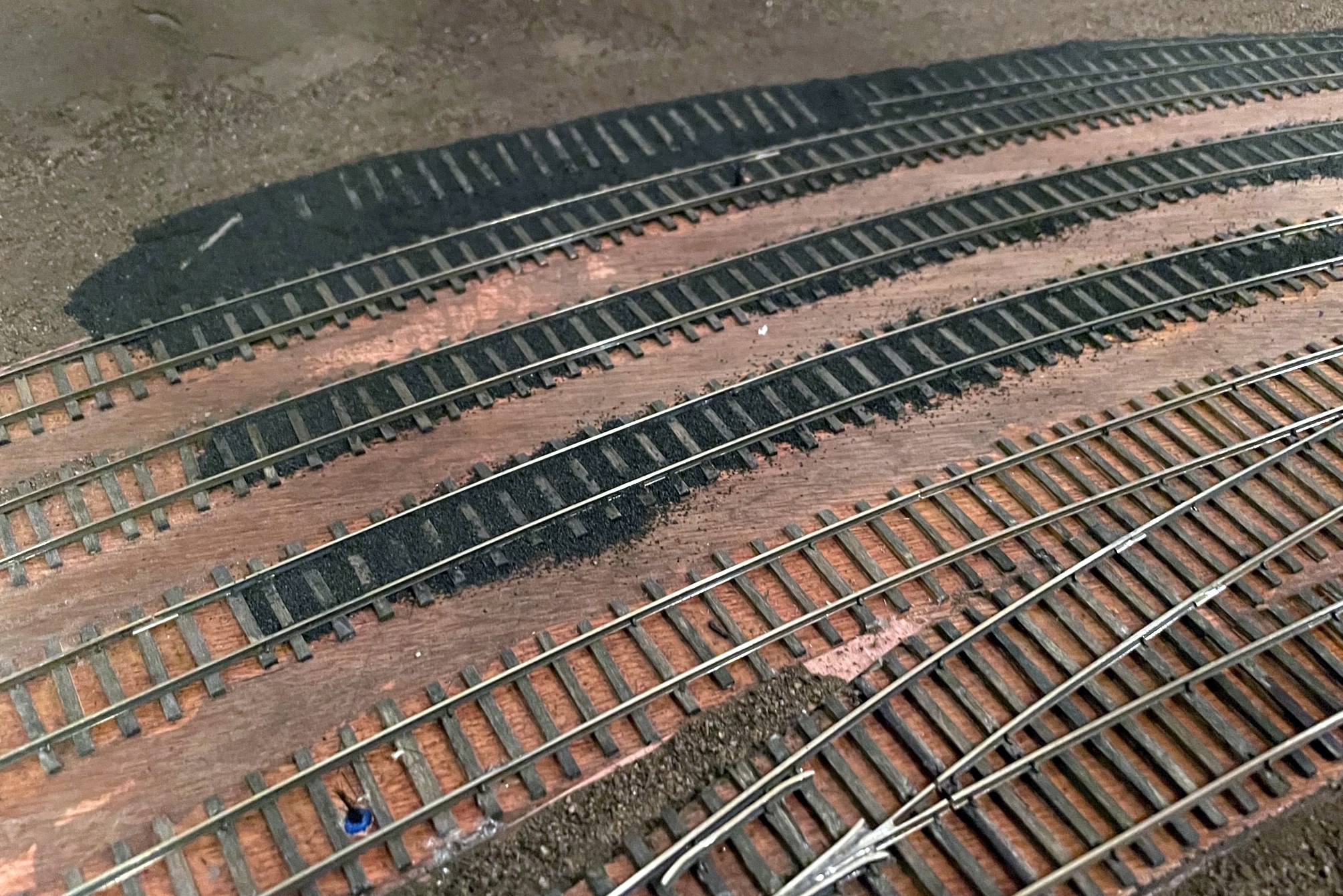
For yards, I did multiple tracks at a time, starting with the gauge, then filling in the areas between tracks
Even when working on multiple tracks at a time, I still wet and glued the gauge portion of all the tracks first
Here’s the finished ballast at the Mayflower tipple–the road is made from fine ballast as well
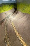
Transitioning from rock to cinders is done abruptly, but I sprinkle rocks to make a better transition
The St Charles yard where the main is clearly visible. The gray areas on top of cinders represent tie repairs after the age of cinders
Here’s the St Charles wye with ballast. Note the area of cinders where a track used to be
I piled more cinders on top of the rails where the engines sit to simulate grime build up
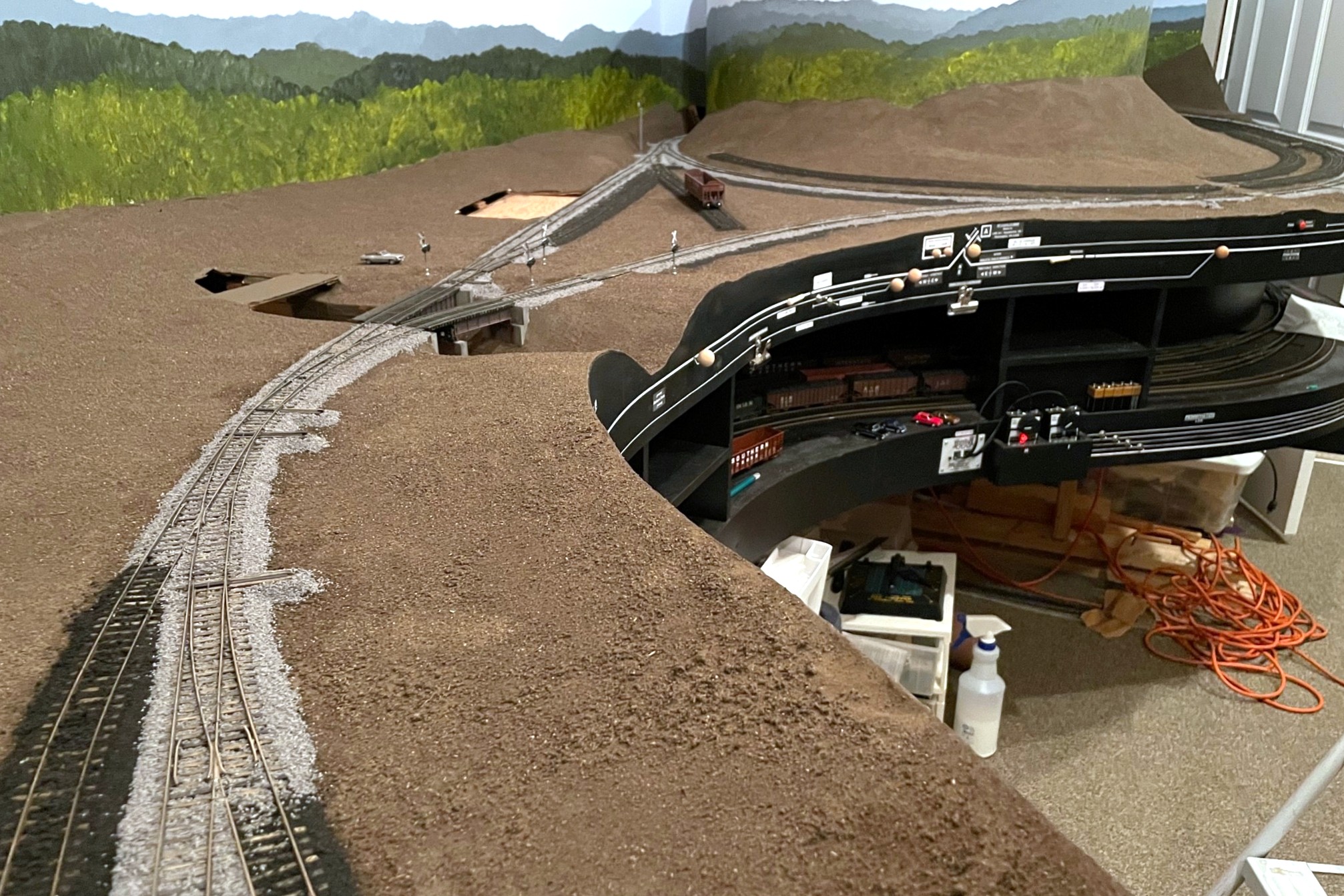
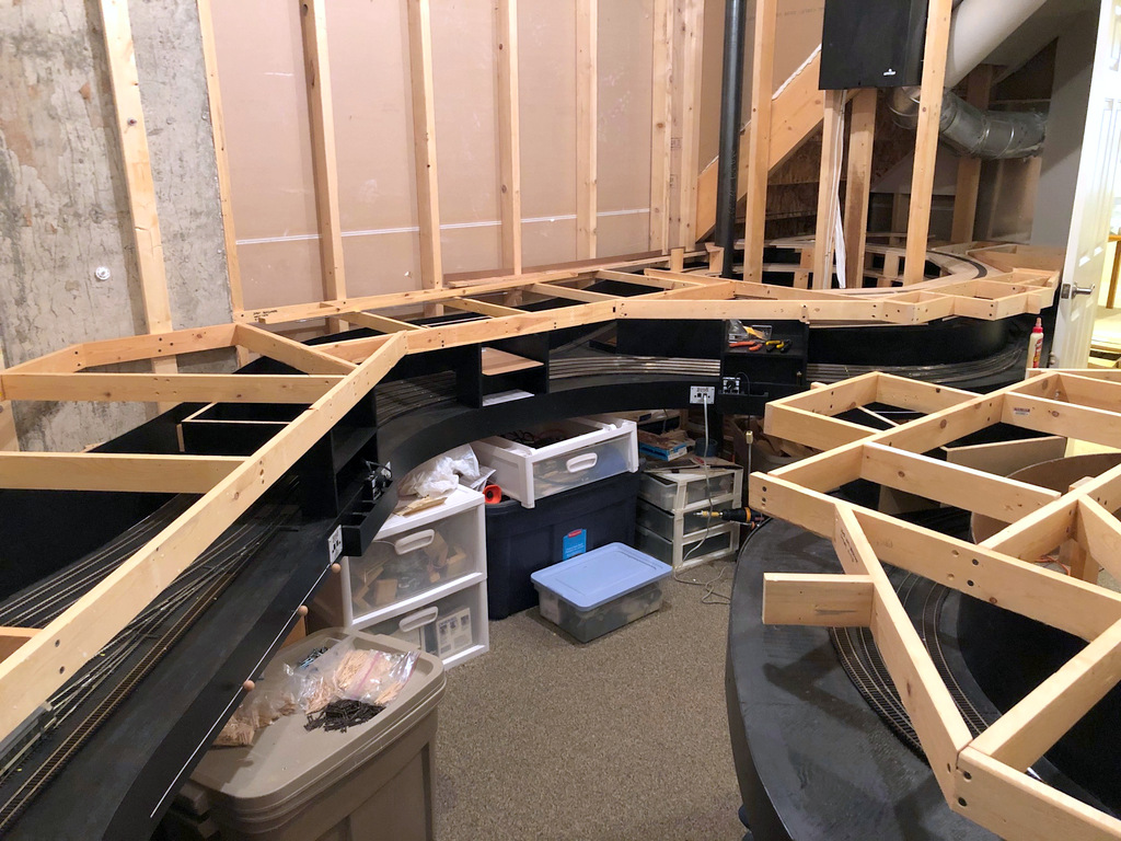
Here’s what the layout looks like from the door as of October 2023–this is from eye-level, so you can see where the upper deck will sit
Just a quick progress update. This week I passed a major milestone by completing the scenery base on the lower level to the “dirt base” level. This is the minimum I wanted to complete before moving to the upper level, so now nothing stands in the way. I’m debating doing a little track ballasting and a couple more mock-up tipples, but it’s exciting to finally be at a point where I can start putting in upper-level benchwork! I found a pic from three years ago to show the progress over time. I’m sure not moving fast, but there’s definitely been a lot of progress!
Looking back toward the door and the Mayflower Tipple. If you follow the tracks back from Mayflower on the right, you’ll pop out at the far end of the aisle on the left
Looking along the St Charles yard with the wye ahead on the left–compare the progress in Oct 2023 to a similar shot from Oct 2020
Similar view as above from three years prior in Oct 2020
Here’s the finished base scenery layer in St Charles as the L&N CV Local waits for Southern train 61 to clear the wye
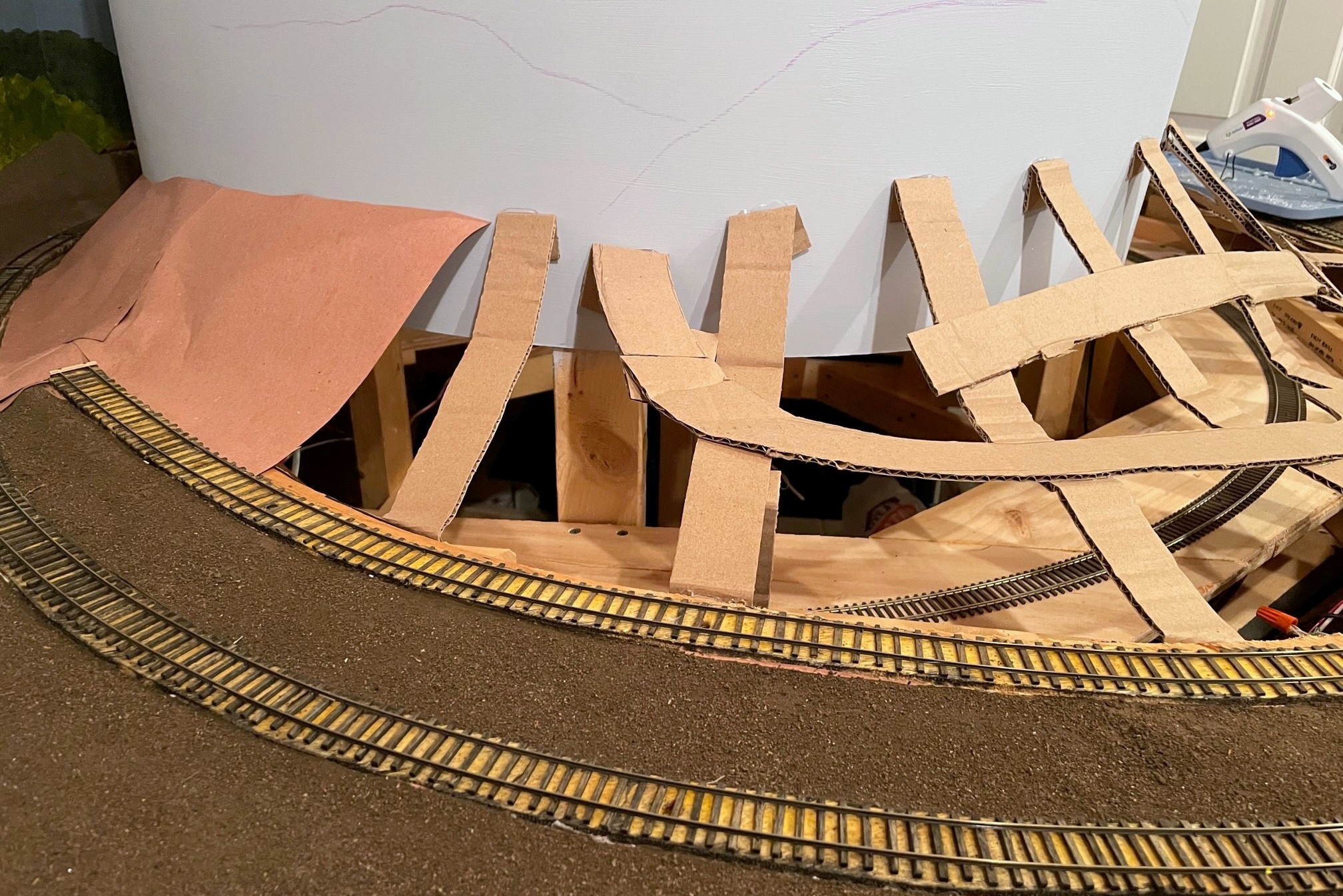
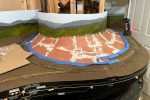
Nearly a year ago I posted the beginnings of building my scenery using Howard Zane’s “paper shell” method. The unfinished red rosin paper shell about halfway through his process served as my basic scenery base for a while–it’s far better than plywood! As I’m nearing the time to move on to the upper deck, I finally got around to finishing the scenery base.
This shot shows several steps in the scenery process including cardboard web, red rosin paper, and the finished base scenery with paint and dirt for texture
In the first post, I covered how to build the basic scenery form using cardboard strips, hot glue, and red rosin paper. Since that first attempt, I have changed my technique a little. I no longer glue a long strip to the backdrop (tedious) but instead just fold the cardboard strip to form a tab and glue the tab to the backdrop. Once the initial cardboard web and red-rosin-paper shell are in place, the next step is a layer of white glue. First, I put masking tape over the tracks and other features I needed to protect from the glue. I use straight Elmer’s white glue from a giant bottle I bought at a local office supply store. It helps to pour a little bit in a portable paint cup for easy access. I used a paint brush (approx. 1.5″ wide designed for house painting) to apply a thick layer of white glue over all the red rosin paper. If your paper layers aren’t tight, expect a little dripping, so be sure to clear out anything valuable from underneath first. When the glue is drying, it saturates the paper causing some unexpected wrinkles–I was worried at first, but most of these disappeared when the glue dried, and those that remained looked like pretty natural variations in the landscape. In places where the paper edges were warping up and away from the layer underneath, I brushed an extra layer of glue underneath and smoothed things back down with a finger.
After applying a layer of glue and letting it dry, I apply lightweight spackling compound to the paper seams to smooth out the edges
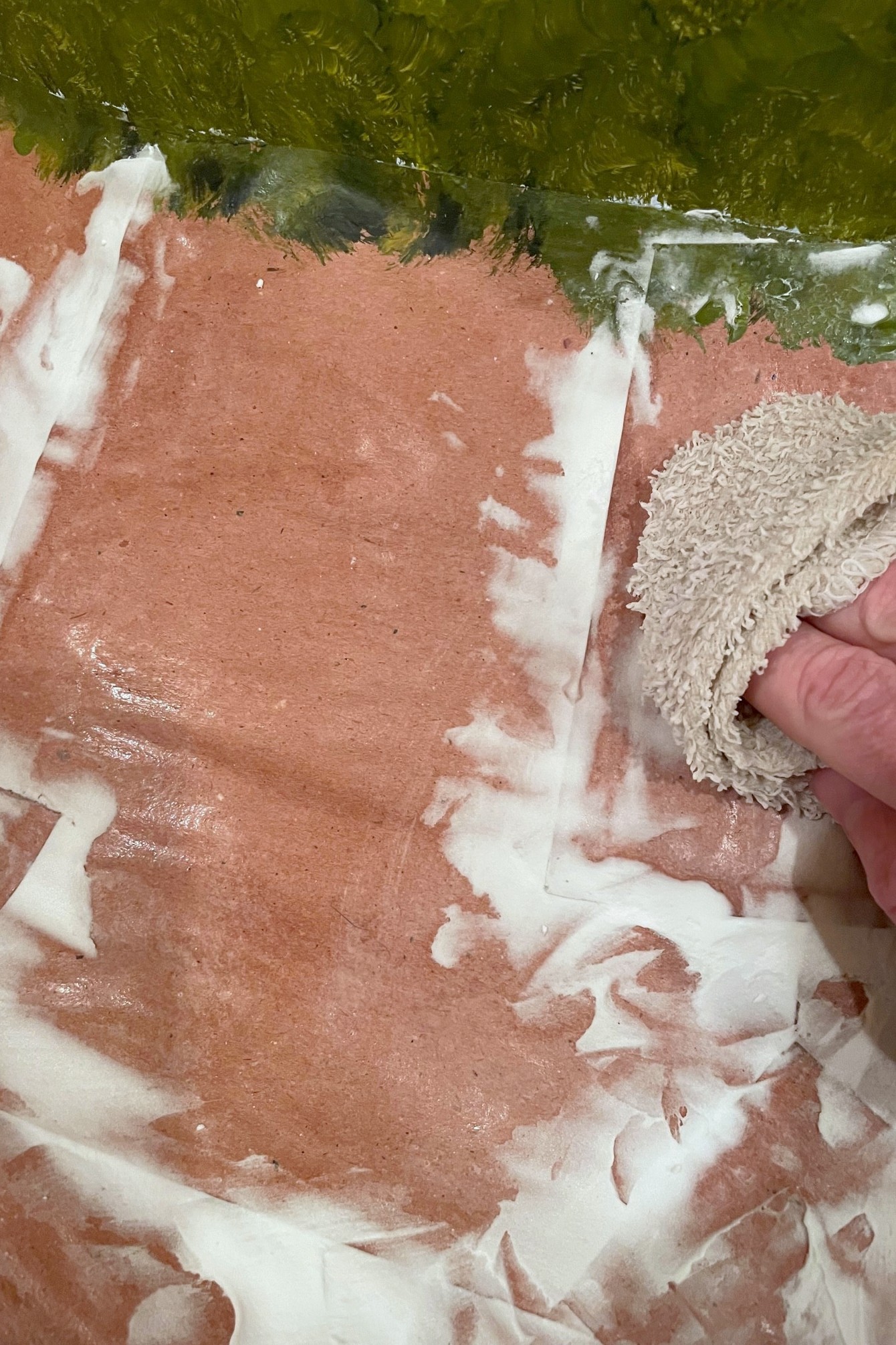
Once the glue dried completely, I added a step that Howard Zane does not: spackling the seams. I wasn’t happy with the edges of the paper as there were distinct lines that wouldn’t look natural with just paint. Additionally, there were a few areas that I needed to be completely flat, but they still had some undulations from the glue step. To fix this, I turned to one of my favorite materials: lightweight spackling compound that I picked up from the local hardware store. This is the same compound I use to cover screw holes and hide joints in masonite fascia and backdrops. It’s about the consistency of icing, and you just spread it on in batches using a plastic putty knife to smooth things out as best you can. Once it dried overnight, I used a wet washcloth to rub down the edges of the spackling compound and to taper it into the surrounding paper. This rewets the compound and allows you to get a smooth surface without sanding. Most of the seams were hidden after the first application, but a few areas required a second or third application to get the shape right.
Once the spackling compound dries, I use a wet washcloth to gently smooth the spackling compound to remove rough edges and blend it into the paper
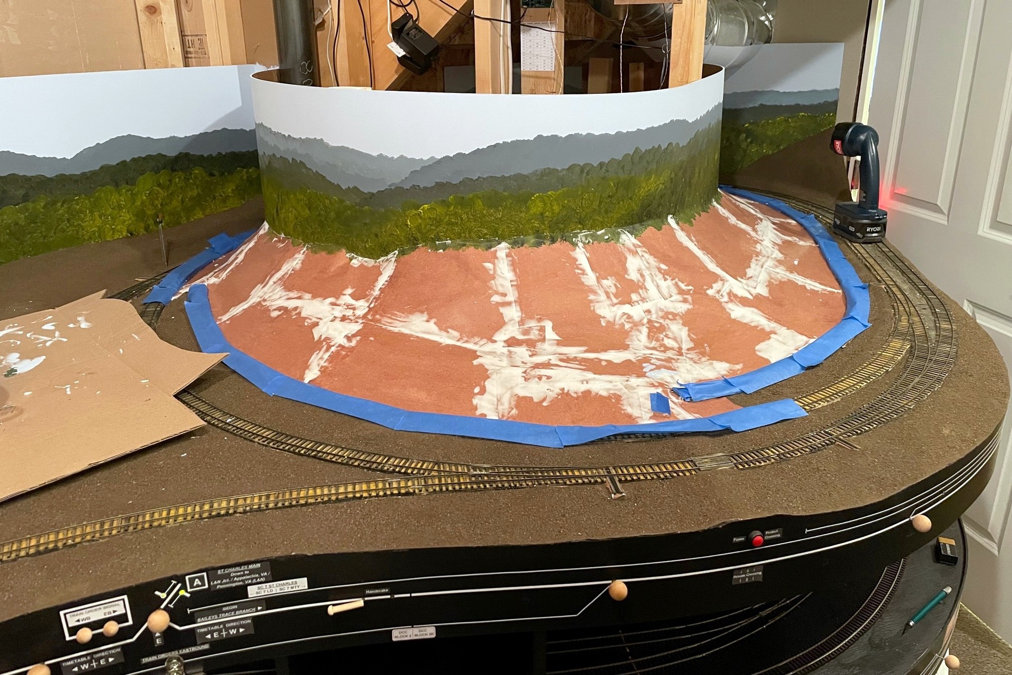
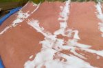
Now things were finally ready for some paint! A friend of mine graciously donated a fine bucket of dark Kentucky dirt to me a while ago (a kingly gift!). I went to the hardware store and found a paint color that matched the dirt color pretty closely and had a gallon made in flat/matte finish. Back on the layout, I applied some of this color thickly with a small brush to about a one square foot area. Using a spoon, I sprinkled some of the sifted dirt onto the paint to give the scenery a little base texture. I left about an inch of the paint uncovered to avoid getting dirt on the paintbrush. Quickly moving to the next section, I painted some more and added more dirt, starting with the seam between the areas as it was the closest to drying. Eventually, the whole surface was covered. Once the paint had dried a little, I gently sprayed a layer of wet glue (about 10 parts water, 1 part glue, with a little dish soap) on top of the dirt. In the few areas where it washed away the dirt, I simply added more to the soaked surface and sprayed again.
I spread thick paint on about one square foot of paper at a time, then I sprinkle with dirt while it’s still wet
Once everything dried. I removed the masking tape and touched up any areas as needed. While there’s still a lot more work to go before the scenery is complete, I’m really happy with this technique to get to a good scenery base that looks a whole lot better than either plywood or raw red rosin paper! I won’t finish the scenery until the upper deck is complete to avoid ruining anything with sawdust and scenery materials raining down, but this current layer is resilient enough (and able to be vacuumed) to withstand the construction of the upper deck.
Another view of the base scenery in St Charles looking toward the gap where the tracks descend to Appalachia staging
This shot shows several steps in the scenery process including cardboard web, red rosin paper, and the finished base scenery with paint and dirt for texture
Here’s the finished layer of red rosin paper on the new scenery section
After applying a layer of glue and letting it dry, I apply lightweight spackling compound to the paper seams to smooth out the edges
Once the spackling compound dries, I use a wet washcloth to gently smooth the spackling compound to remove rough edges and blend it into the paper
Here’s the finished layer of paper with a layer of glue and a layer of spackling compound smoothed with a wet washcloth and ready for paint
While I would have preferred western Virginia dirt, a friend was gracious enough to bring me a bucket of Kentucky dirt to use on the layout which is far closer than our local Colorado dirt
I spread thick paint on about one square foot of paper at a time, then I sprinkle with dirt while it’s still wet
After the paint dries, I spray a wet glue mixture over the dirt to help secure it–I patch up any bald areas with more dirt
Applying glue to red rosin paper results in some warping of the paper that I find adds extra texture and interest to the scenery without any extra work
Paper shell scenery can be made into complex contours using many smaller pieces and a bit of patience
Here’s the finished base scenery layer in St Charles as the L&N CV Local waits for Southern train 61 to clear the wye
Another view of the base scenery in St Charles looking toward the gap where the tracks descend to Appalachia staging
Handbrakes in action holding empties securely above the Mayflower tipple
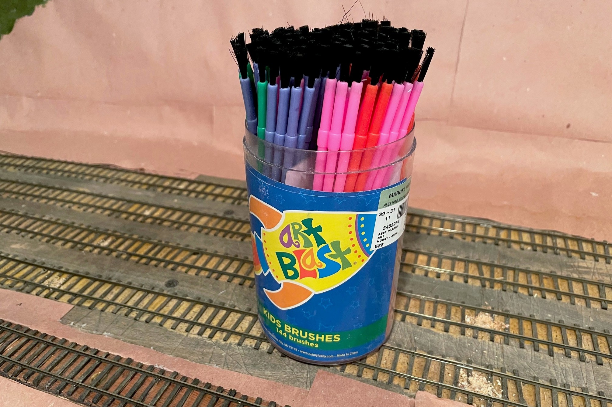
The ability to set handbrakes to keep cuts of cars in place on a grade is a crucial part of railroading, and a model railroad is no different, especially one set in the Appalachians. I’ve covered my technique for building manually deployable handbrakes via a retractable wire between the rails (article here), but the controllable brakes are complicated to make and install, so I reserve them for areas where I’ll be holding long cuts of cars on a steep grade or for where I need to hold a car for a while and then let it loose for some “gravity assisted switching.” But there are several dozen spots on the layout where I’ll need to spot small cuts of cars on slight grades, so for these areas, I wanted something simpler. I also like free-rolling cars, so tricks like putting a tiny spring on the end of one of the axles was also off the table–it needed to be something in the track. Enter the cheap plastic paintbrush! Each paintbrush handbrake costs just cents to make, and I can easily make and install a dozen in under an hour.
I picked up a box of 100 inexpensive plastic paintbrushes a couple years ago when the local Christian bookstore was having a big sale. I didn’t know how I would use them, so I put them away for a rainy day. That day came when I was playing around with different ideas for holding cars in place. It needed to be something I could roll cars and locomotives across easily without derailing or causing too much friction that would also be sturdy enough to hold a car when spotted over the brake. I first tried two methods that I’ve seen work for others. The first is a little dot of CA on top of the rail, but many of my spotting points were just too steep for this. Next I tried little lengths of fishing line mounted between the rails–these are good because they’re tough to see and work pretty well, but they make a noticeable “plink” every time they clear an axle or a hopper bay… in sections of the yard where I had several in a row, it sounded like a tiny music box playing a discordant tune!
The starting point for handbrakes are inexpensive plastic paintbrushes from an art or hobby store
Then I remembered the brushes. The plastic bristles are pliable enough to give when trains are moved across them but stiff enough to hold a car when no other force is exerted. They could also be trimmed both in height and in density using a pair of scissors. They are certainly more noticeable than the fishing line or CA dots, but my hope is they’ll blend right into dirty coal-covered tracks, and those that don’t blend in can be painted to look like weeds. Even with nothing to disguise them, I find they don’t draw the eye much anyway.
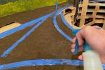
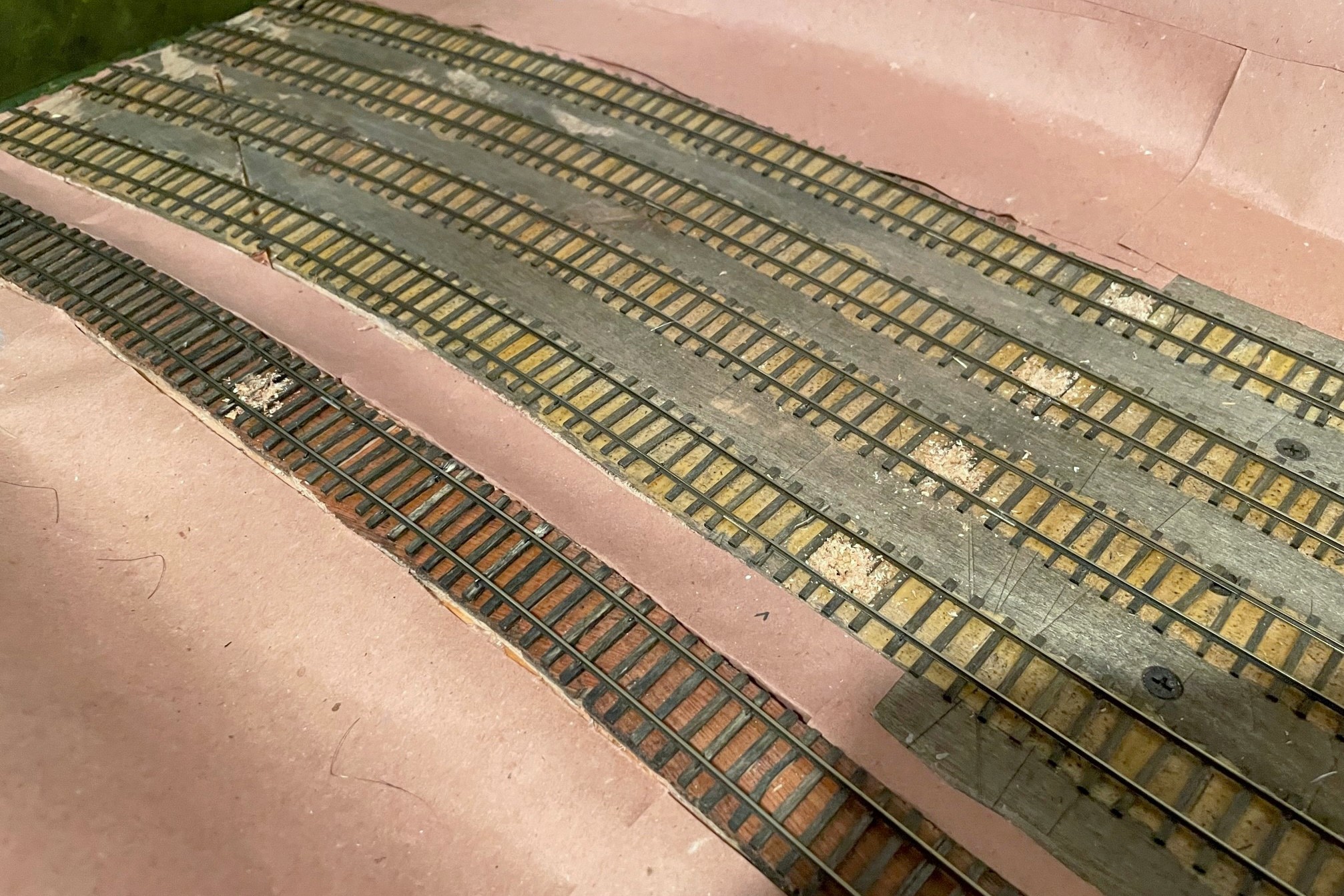
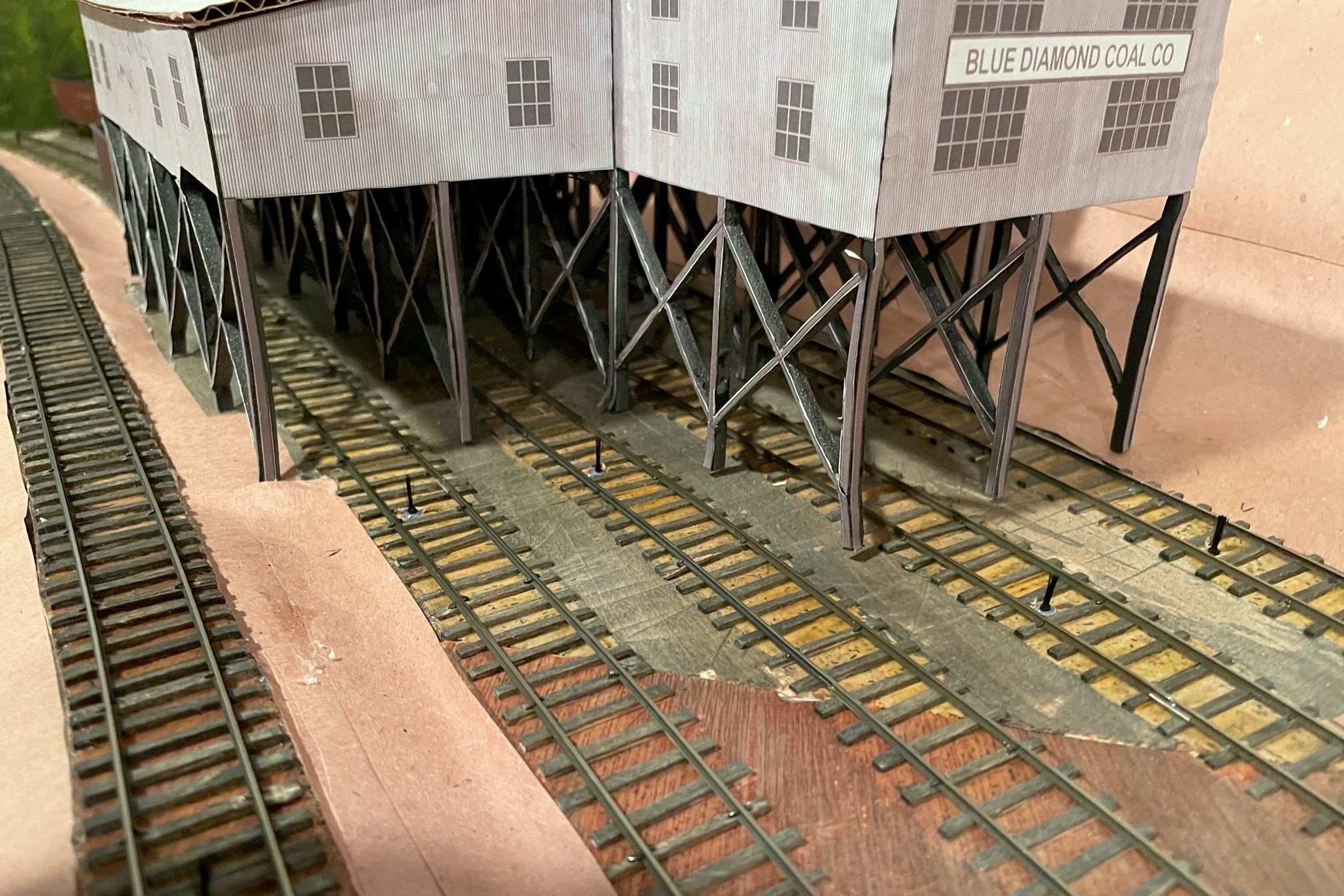
Step 1 is to locate where you need the brakes and drill a hole–the hole is offset to avoid wear-and-tear on air hoses
The first step is to locate where you want to install the “brake.” Figure out where you want the car or cut of cars to sit, then mark the spot where the most downgrade axle will sit–this is where you want the brake. In some cases, like the end of a track, you can mark the spot of the downgrade axle of the upper truck–I use this at the end of stub tracks where I need all the room I can get. For tipple tracks, I find it useful to have up to four handbrakes per track. One at the uphill end of the empty track to hold a full cut of empties, one just above the tipple to hold a shorter string of empties, one just below the tipple to hold a shorter string of loads, and one just before the fouling point of the downhill switch to hold a longer string of loads (or any “gotaways”).
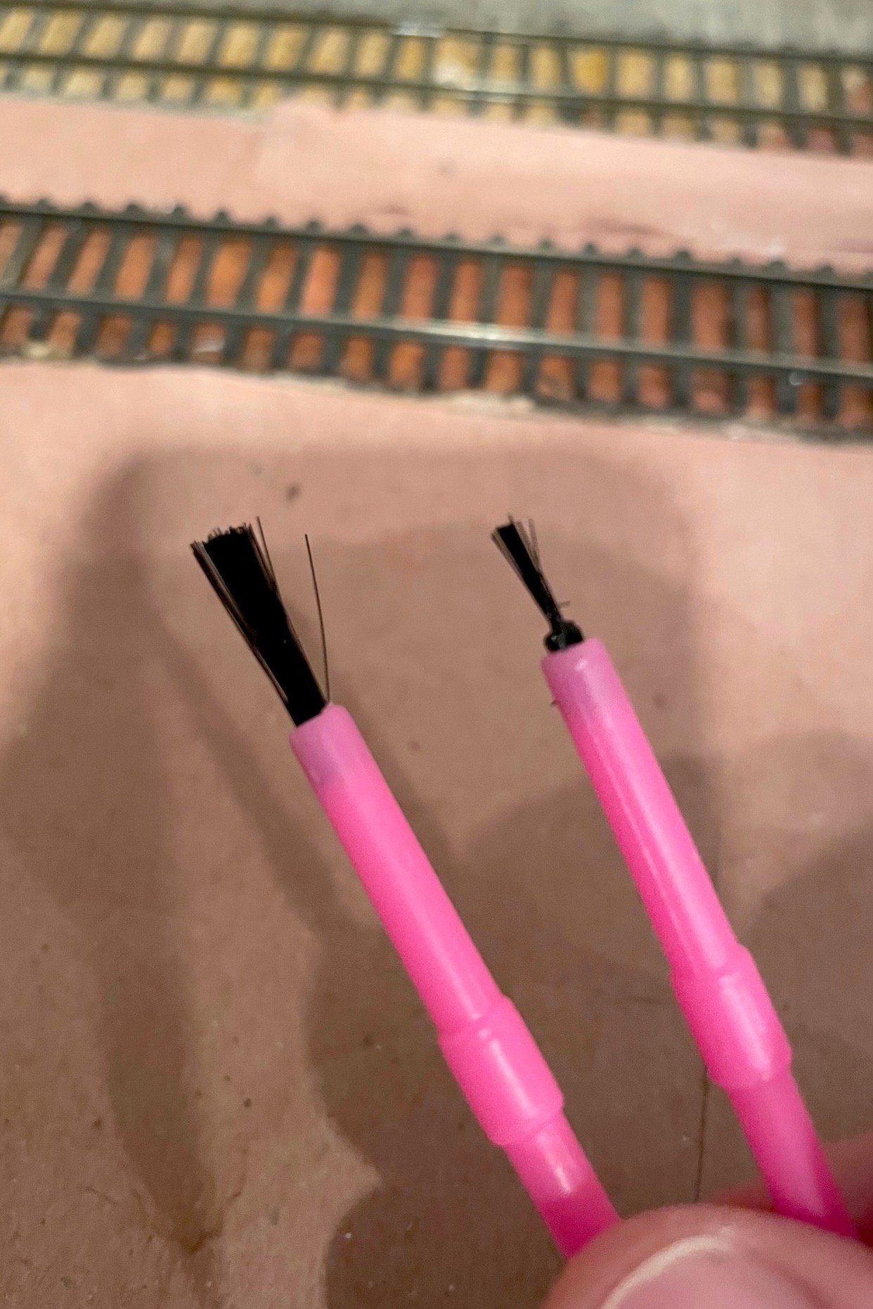
Starting and ending points with the brushes, just a little off the top and thinned down with scissorsThe finished “brake” ready to install between the rails
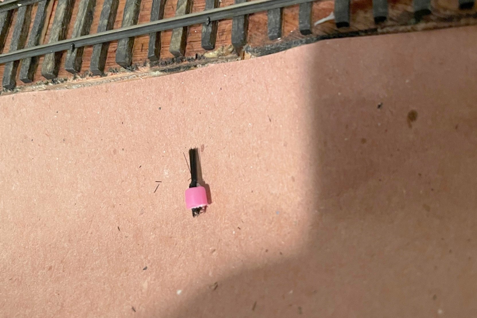
The second step is to drill a hole between the ties for each hand brake location. I found a 5/32″ bit drilled about 1/4″ deep worked for my paintbrushes, and I offset my holes closer to one rail to avoid constantly hitting delicate air hoses on cars. To prep the paintbrush, I first cut off about 3/16″ of the bristles with scissors–the idea is to have them tall enough to catch axles but not the sills of the cars or cut levers. Then I thin out the bristles by repeatedly cutting into the brush with just the tip of the scissors while rotating the brush around. How much you thin it out depends on the grade and how many cars you want to hold, but for my light grades, I trim down to about the last 20 or so bristles. It’s easy enough to thin them a bit more once they’re installed, and if you get it too thin, it’s easy to just make another. Then I use scissors and cut off the brush end of the paintbrush leaving about 3/16″ of the plastic handle to keep the bristles secure. Installing them is usually a press fit, but if they’re loose, a little carpenter’s glue will help hold them in place. I press them down until the handle is below the ties where its bright color will be covered up by ballast.
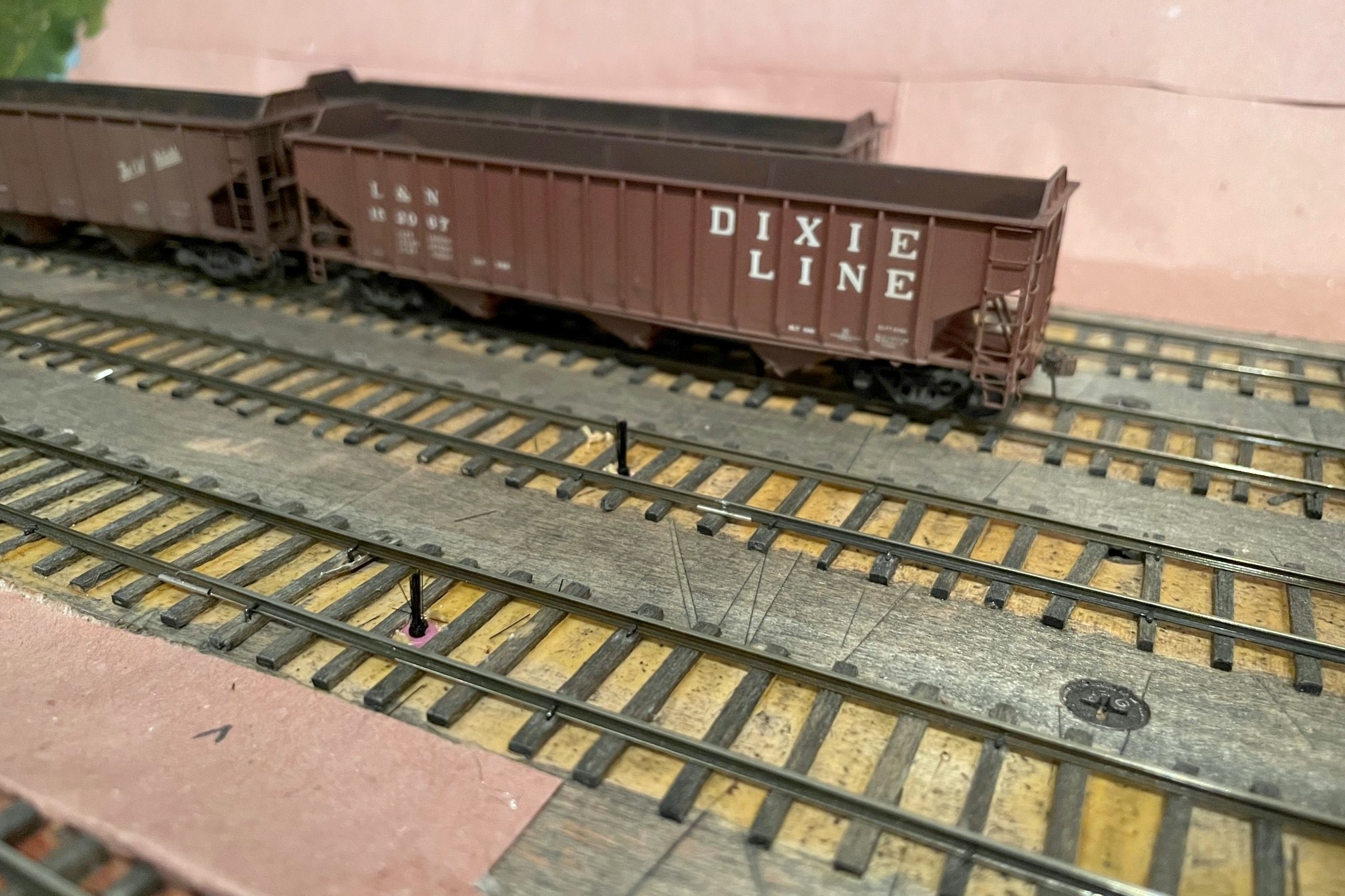
Paint brush handbrakes installed between the rails
The final step is to test the brake by running strings of cars across them to make sure they don’t derail and don’t cause any noticeable jerking movements in the cars (if you look closely, you’ll see some movement, you just want to avoid it being distracting). When you let go, the cars should roll and then come to a gentle stop once they hit the brake. Also test a locomotive across each brake to make sure it doesn’t interfere with the trucks (this is the most stressing pressure on the brake). On steeper grades, you may find having a few brakes in series is needed to stop a string of rolling cars, or you may have to spot the cars exactly on the brake to prevent them from rolling in the first place. It’s easy enough to add and remove these brakes while you’re trying to figure things out. In the end, I’ve found this is a great way to hold cars in place without the worry of damaging cars or scenery, and it’s tough to beat the price and ease of installation!
Finished “handbrakes” to hold the loaded cars in front of the Mayflower tipple mock-up
The starting point for handbrakes are inexpensive plastic paintbrushes from an art or hobby store
Step 1 is to locate where you need the brakes and drill a hole–the hole is offset to avoid wear-and-tear on air hoses
Starting and ending points with the brushes, just a little off the top and thinned down with scissors
The finished “brake” ready to install between the rails
Paint brush handbrakes installed between the rails
Finished “handbrakes” to hold the loaded cars in front of the Mayflower tipple mock-up
Handbrakes in action holding empties securely above the Mayflower tipple