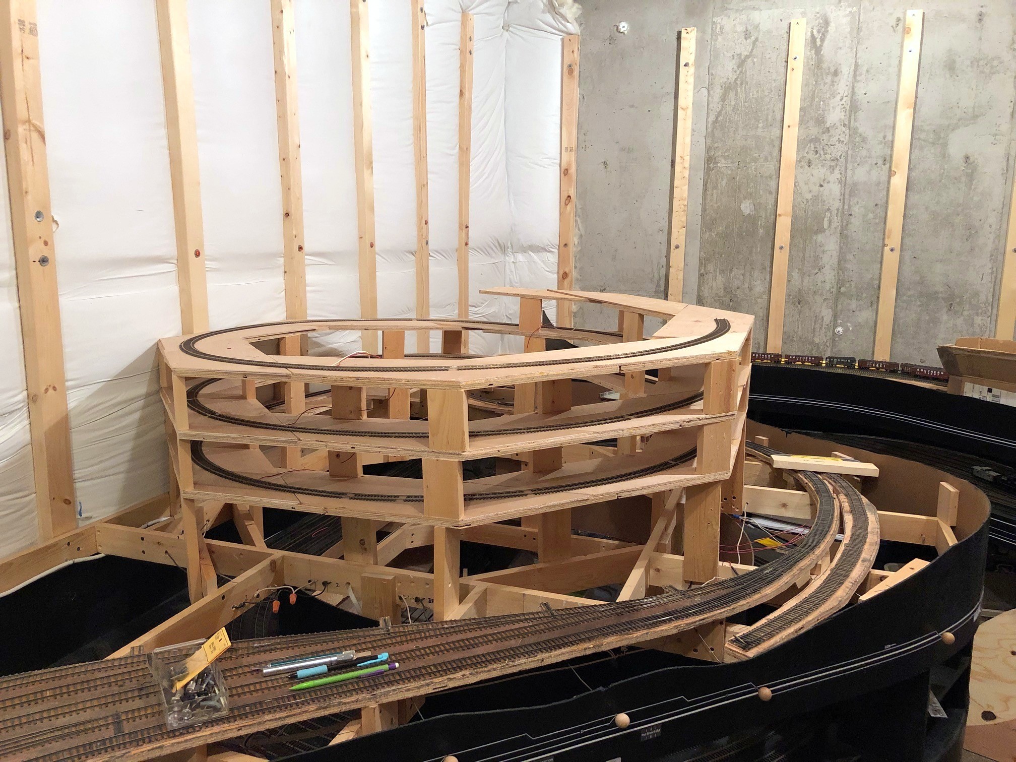
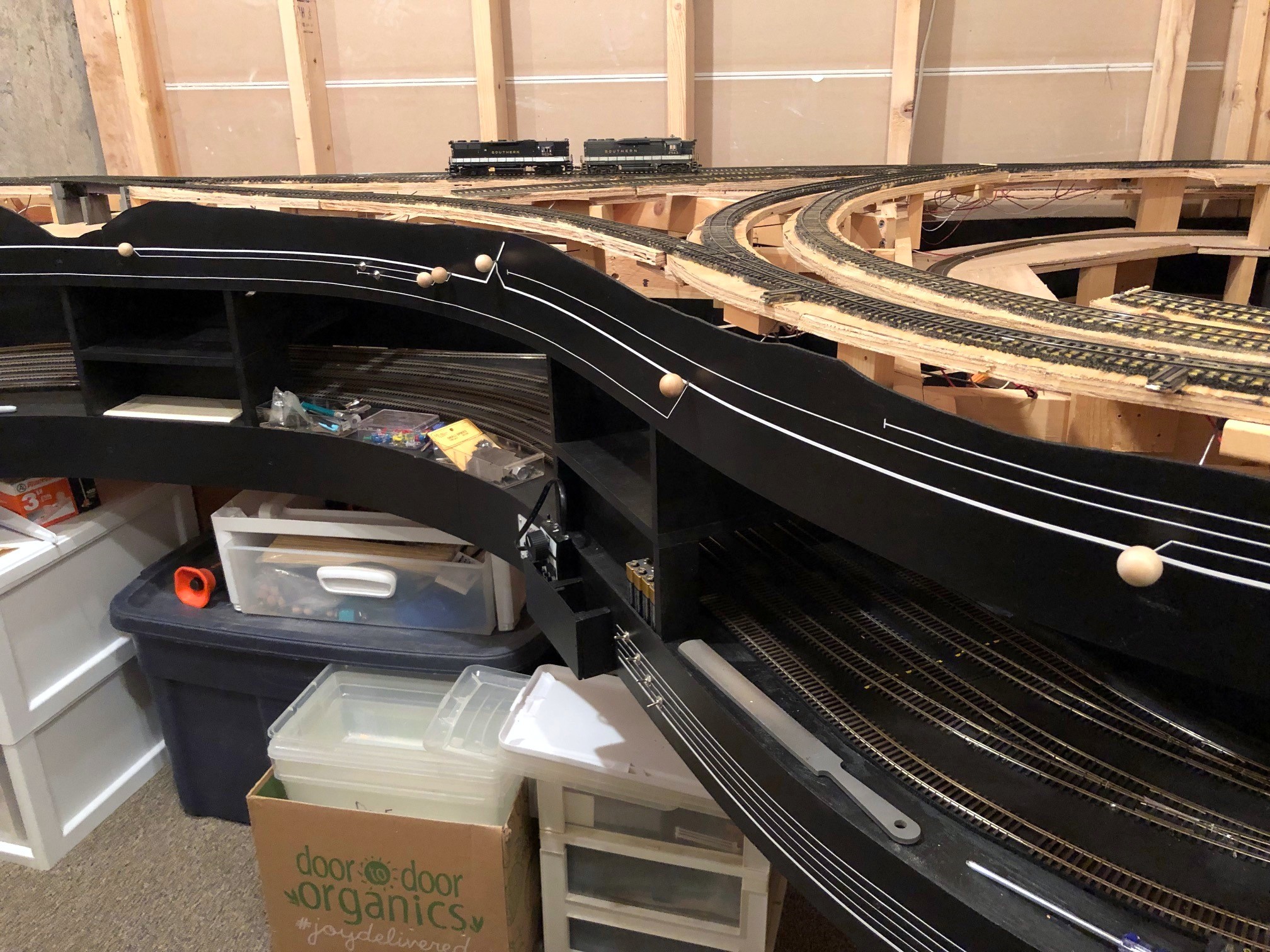
The finished helix! From here it will traverse the concrete wall in the background before emerging at Turners Siding
Reached another milestone yesterday–the main helix between the main and upper levels is now complete! I have track reaching to 58″ off the floor. Like the helix between staging and the main level, I used what I call the “double pinwheel” method of building a helix (click here for a full write up on the double pinwheel helix). It requires only straight-line cuts, it’s very forgiving of non-precise cuts, and it’s rock solid.
The helix joins the town of St Charles to the towns of Turners Siding, Kemmergem, Monarch and Benedict on the upper level. The grade (3%) starts at the RR-west end of St Charles yard and continues up three turns of the helix. There will be another 15 feet of hidden track before the line emerges, so that’s effectively a fourth turn’s worth of elevation gain after the helix. Of course, when I built the base supports for the helix, I miscalculated something that had the initial grade into the helix closer to 4%. At first I was like, “well, maybe it will work.” I test ran a few locomotives up the first loop (all I had constructed upon discovery), and while my lightest locomotive could still pull 11-12 cars up the grade, I finally wised up and decided to fix it before it became unfixable. After dropping to 3% (lowering all the supports by 3/4″), the lightest locomotive could again haul 14 cars and a cab from a dead stop up the grade, the same limit as the helix from staging. I’m sure I will be glad I made this adjustment in the future! Measure twice, cut once… thankfully it just required loosening and reattaching some screws and only a few new cuts of supports to fix it.
It will be a little while now before I start the upper-level benchwork, but finishing the helix will allow me to install the lower-level backdrop, so the beautiful insulation pads will no longer be visible on the main level. I know that will be a big disappointment to many of you who feel the insulation just adds an extra layer of realism… ok, enough sarcasm. Building helixes isn’t fun for many modelers (including me), so I’m very glad this portion of the layout is now complete!
The first level of the helix installed before discovering I needed to lower it 3/4″
Continuing up the helix using the double pinwheel method
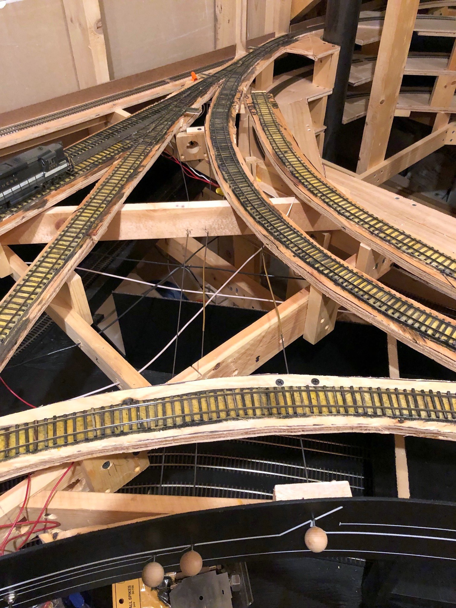
Helix almost complete
The finished helix! From here it will traverse the concrete wall in the background before emerging at Turners Siding
Operations, in my own words, is simply the means by which a railroad – or a layout – moves things to the intended location while keeping trains from colliding over a shared set of rails. Paperwork is an important part of railroading operations, so it stands to reason that paperwork should also be an important part of any operations-oriented layout. No one REALLY loves paperwork, though, so how much is enough? There are as many answers to this question as there are operating layouts, but I’ll share what I’ve settled on because I believe it strikes a pretty reasonable balance and works well for a sleepy coal branch layout like mine.
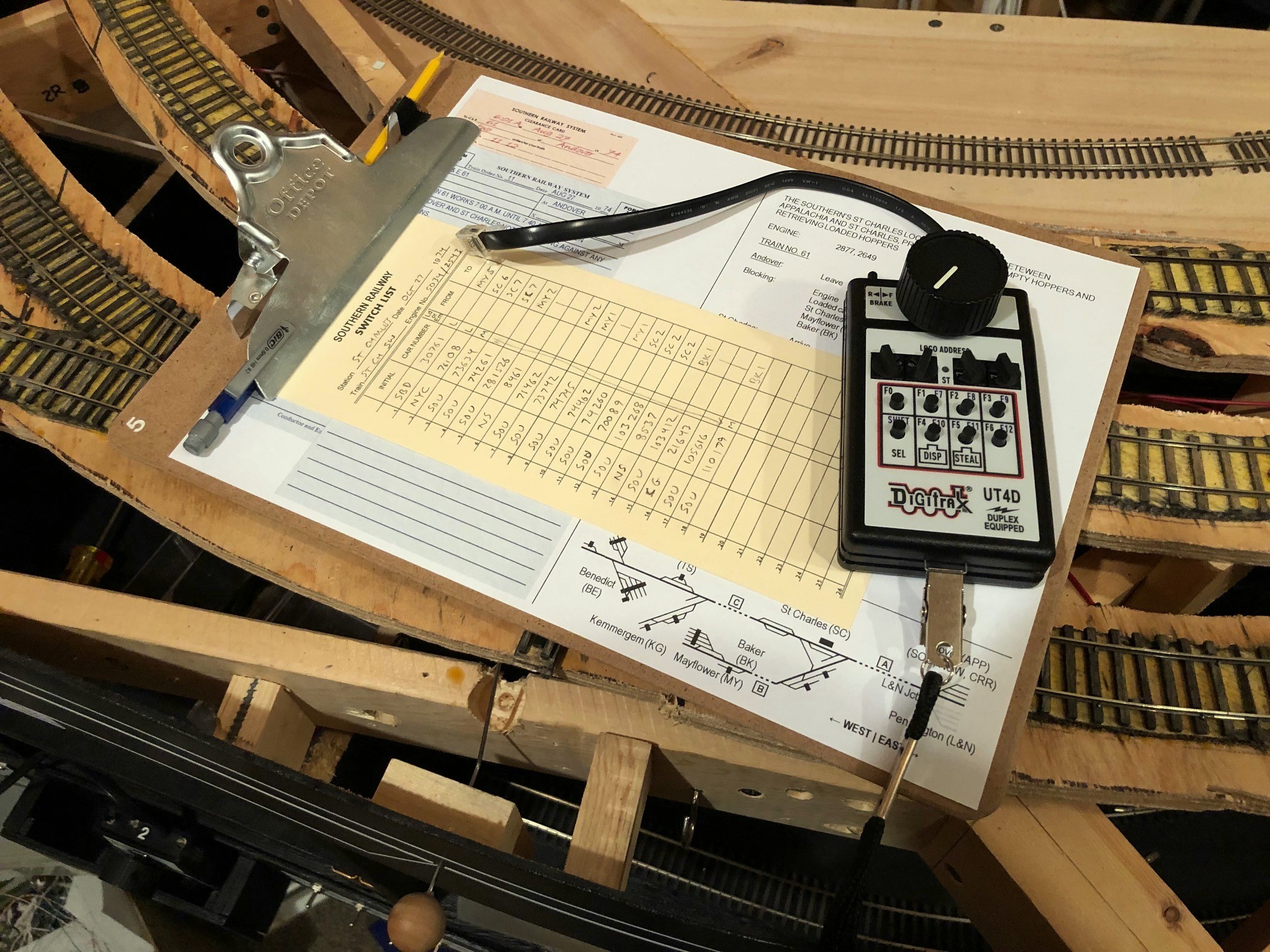
Everything the St Charles Local needs to operate on the layout
My goals for the layout’s operations:
Replicate essential elements of the prototype’s operation
Make paperwork realistic without being overwhelming (and avoid tedious paperwork that serves no modelable purpose)
Make it easy for operators to work their trains like the prototype and get the cars to the right place with minimal training
Avoid creating any boring jobs on the layout (a dispatcher would be a boring job on this layout and thus would always fall to the host)
No car cards (I realize I’m tipping some sacred cows here…)
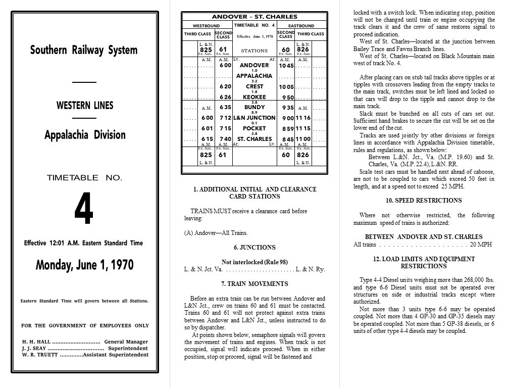
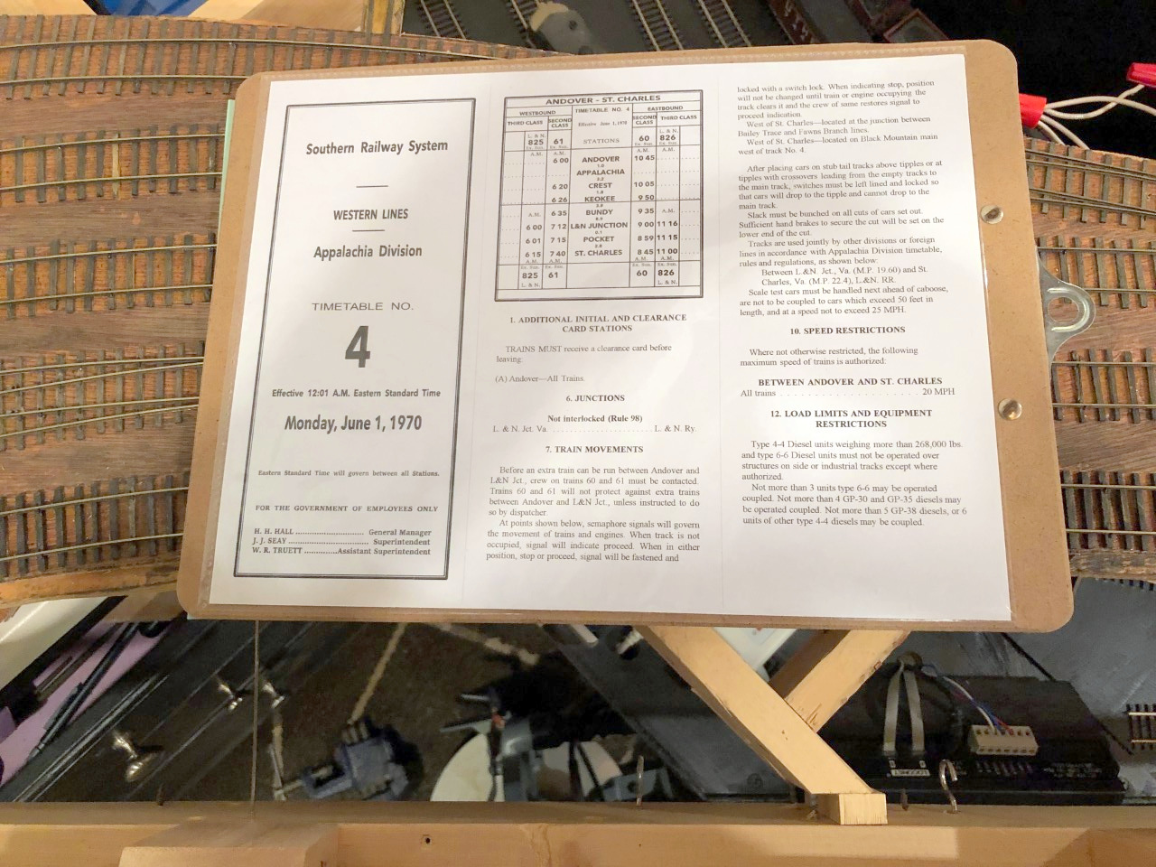
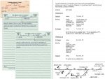
The first step was to understand operations on the prototype St Charles Branch. To help, I had photo captions, excerpts from articles, and some notes from individuals who worked in the area, but the real score was an Employee Timetable (ETT) of the Southern’s Appalachia Division circa 1970. Employee timetables are a critical piece of paperwork on the prototype. They list the scheduled trains for each line, the “class” of each train, the stations they run through, and their scheduled arrival times for each station. In a timetable and train order operations scheme, lower class or unscheduled trains (extras) must keep clear of higher priority trains in the timetable. While the timetable sets the basic scheme of operations, the dispatcher uses train orders for each crew to handle the details, telling them where and when they can work, what trains they need to meet and where, etc.
The Southern’s Appalachia Division dispatcher controlled far more than just the St Charles Branch, so a dedicated dispatcher for my railroad that employs 2-3 operators per session and no more than 2 trains simultaneously would be overkill. In the name of “avoid creating any boring jobs,” I wanted to see if I could completely simulate the role of the dispatcher in keeping the trains moving and separated without actually having a human playing the dispatcher on the layout.
Part 1. Moving the Trains
Employee Timetable
The Appalachia Division timetable listed one Southern second-class train each direction from Andover (the main coal-field yard near Appalachia, VA after 1965) to St Charles daily except Sunday (same crew with a different number for the outbound and return trips) along with one third-class L&N train each direction from L&N Junction to St Charles. All other trains, including the “St Charles Switcher”/”Black Mountain Local” mine runs out of St Charles would run as extras and have to steer clear of the scheduled trains.
Additionally, timetables list all the unique rules and procedures for that division including things like speed limits (20 MPH for the whole St Charles Branch) and instructions for working specific sections of track. One of the interesting sections in the Appalachia Division ETT reads as follows:
“At points shown below, semaphore signals will govern the movement of trains and engines. When track is not occupied, signal will indicate proceed. When in either position, stop or proceed, signal will be fastened and locked with a switch lock. When indicating stop, position will not be changed until train or engine occupying the track clears it and the crew of same restores signal to proceed indication.
West of St. Charles—located at the junction between Straight Creek and Gin Creek branches.
West of St. Charles—located at the junction between Bailey Trace and Fawns Branch lines.
West of St. Charles—located on Black Mountain main near east end track No. 5.”
I had heard about one of these semaphores from a former Southern employee who once worked in the area, but now I knew exactly where they were located and how they were used. This was perfect for my layout because I could use two of the three semaphores to protect long sections of hidden track (e.g., the helix between St Charles and Turners Siding), and best of all, the crews do the work to protect themselves on these lines without the need for a dispatcher or hard-to-model procedures like a fusee or flag.
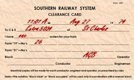
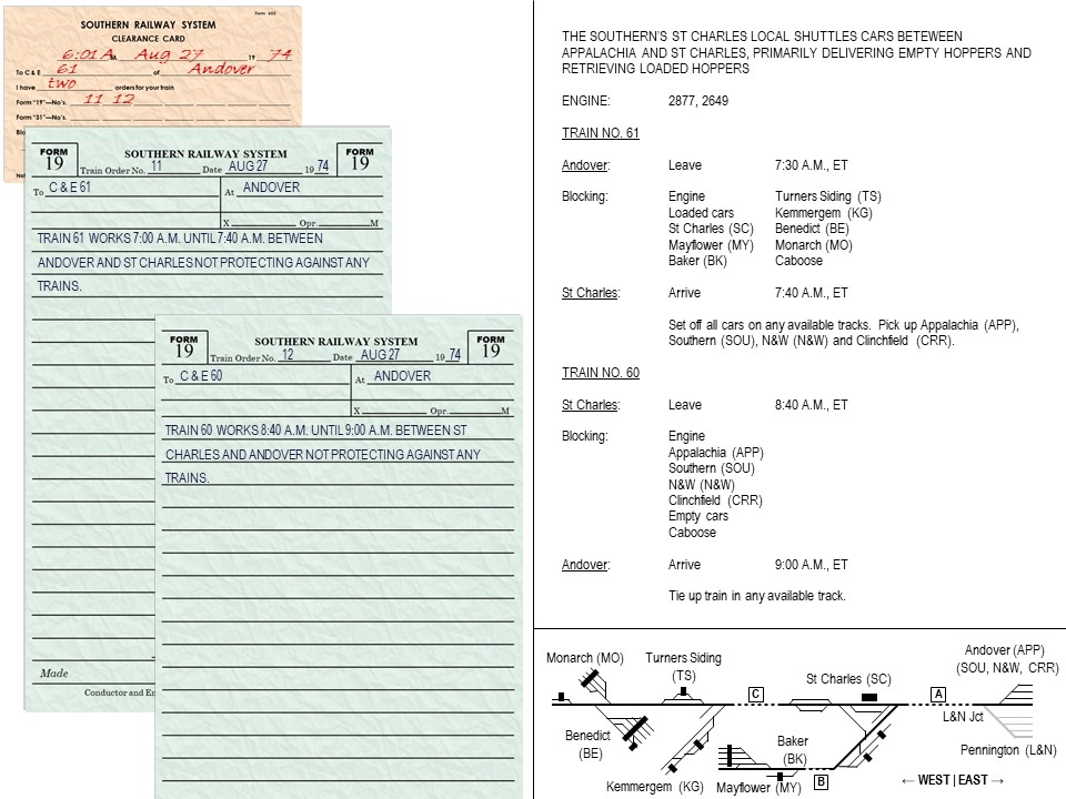
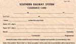
Clearance card showing how many orders the crew has
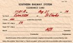
Even with these semaphores, trains still used orders giving them clearance to run. Train orders give crews instructions and authorization to occupy certain sections of track and to meet other trains. The dispatcher issues the orders to the conductor and engineer of each train, and the orders can be given over the radio or passed along to the crew by an operator at a station along the way (this was the primary use of semaphores at Southern stations–to tell a crew if they could proceed or needed to slow or stop or pick up orders). I’m no expert on orders, but the two common orders on most railroads are the Form 19 and the Form 31, similar forms in content, but crews needed to stop and sign a Form 31 while a Form 19 could be issued “on the fly.” The Southern seemed fond of the Form 19 while the L&N seemed to use more Form 31s, so I decided to use both. With no dispatcher, I also decided crews would start their jobs by receiving orders telling them their clearances and any other special authorizations or provisions. The practice of picking up orders before moving the train is prototypical, but of course, the train orders were not enough paperwork for the crews by themselves, so the Southern (along with other railroads) required all crews to have a “clearance card” before departing. The clearance card tells the crews how many orders they have and the order numbers for accountability–paperwork, after all, is all about authority and accountability.
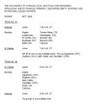
So, to get trains working when desired and to keep them from colliding, I would need a timetable, clearance card, train orders, and a couple of semaphores. The actual Appalachia Division Timetable is more than 20 pages long, but I really only needed the sections that 1) apply to the St Charles Branch, and 2) apply to model operations. I’ve created a very condensed, single sheet version of the Appalachia Division ETT which has a cover (having it LOOK like a timetable is important to me), a simplified recreation of the timetable for Andover-St Charles, and instructions such as speed limits, use of semaphores, etc. that would be relevant to a model operator. I used the exact verbiage from the Southern timetable in most places, so it has the “feel” and function of the real thing without requiring an operator to read a 20-page document before running their train. To give it even more authentic feel, I took the time to match the the fonts and formatting as close as possible to the real thing–this took a long time, but I feel it’s well worth the effort. While Microsoft Word or Publisher may seem like the best programs to use, I find it’s far easier to build complex documents in Microsoft PowerPoint where I can control text boxes and shapes better. By taking the time to match the feel of the prototype ETT, the layout’s timetable becomes more than just a source of essential information on schedules and rules; it’s one of many parts designed to transport an operator into the layout’s time, place and purpose. It reminds them they’re working on a piece of the Southern Railway, that their operation is part of a larger “Appalachia Division,” that they’re running a part of a transportation system and not a toy, and their train’s purpose extends beyond the modeled portion of the layout.
My one-page recreation of an Employee Timetable for the St Charles Branch
Train Orders
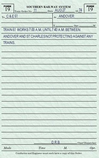
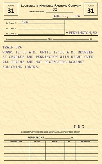
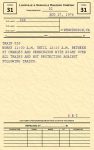
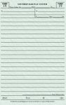
An example of my model Southern Form 19 train order
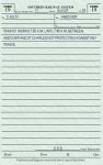
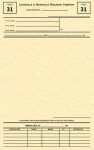
With the timetable in-hand, I now turned to train orders. Because there are very few trains running simultaneously on the St Charles branch, a single set of train orders would likely be sufficient for each train, and because all trains start at a “station” which, in reality, had an operator who could hand orders to the crew, it would be realistic to hand the orders to the crew when picking up the train. To create the train orders, I found images of actual train orders from my era online to use as examples for both the Southern and L&N. Train orders were often given in very simple and standardized language–easy to recreate and easy for a model operator (i.e., non-railroader) to understand. The Southern’s Form 19s were hand-written or printed in bluish ink on semi-transparent green paper, so I use a little color and underlying texture for my rectangle shapes to get this look out of a printer. I found some examples of Southern clearance cards and the L&N Form 31s in a book as well. Like the timetable, I took the time to recreate the Southern and L&N forms as painstakingly as I could in MS PowerPoint. The orders should remind crews they’re working for two different railroads, each with a distinctive culture and personality.
An example of my model L&N Form 31 train order
As far as what goes on the train orders, I try to keep it simple. The timetable mostly keeps the trains separated, so the most common verbiage is the train’s clearance between points on the railroad and the timeframe that clearance is valid. For inferior trains like the L&N’s CV Local (825/826), I’ll add extra verbiage like a reminder to expect to meet a superior train in St Charles and a reminder to use the semaphores for protection while on the western branch lines. I fully expect this verbiage to be refined as 1) I learn more about the prototype and actual orders used, and 2) I have more operating sessions and see what information the crews actually need to be successful at working and keeping their trains separated.
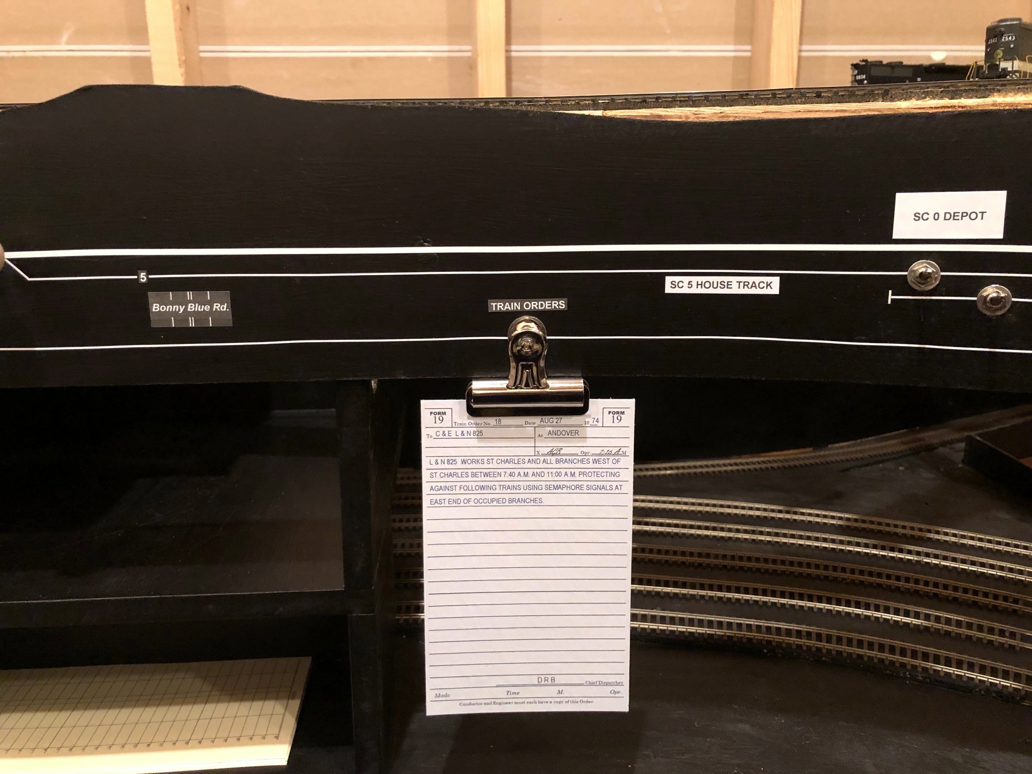
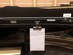
The scheduled trains on the St Charles Branch are “out and backs” which means they have a single crew and set of locomotives, but they’re technically two trains, one in each direction. This means most crews will have at least two train orders. The L&N crews receive clearance from the L&N dispatcher initially and run according to timetable on the Southern as far as St Charles. From there, they need to pick up a Southern train order to proceed railroad-west past St Charles and work the branches. I’m currently using a clip on the fascia near where the St Charles depot will go with orders to be picked up, and I’ll eventually have a semaphore at the depot I can set to tell the crews to stop.
A train order awaiting pick-up at St Charles
So far I’ve got a way to keep the trains moving and separated without a dispatcher–time to move on to getting the cars to the right locations.
Part 2. Moving the Cars
There are many ways to move cars on a model railroad including tabs on cars, car cards with waybills, and switch lists. The benefit of tabs on cars is the tab (like a waybill tacked to the car) follows the car and doesn’t create a need to carry a lot of extra paper. It also doesn’t need unique car numbers, something important with model runs of single car numbers a couple decades ago. However, for me, tabs on cars is not an option because I don’t want non-prototypical things cluttering up my models and breaking the illusion of reality more than the models are already doing, and all my cars will have unique numbers anyway. Car cards with waybills do a great job of moving a car’s destination from location to location using the prototypical practice of a “waybill” and providing additional details about a car’s lading. On the downside, they require some training (like when to flip a waybill), they require extra space on the layout/fascia at each town, and they require operators to carry a bunch of cards along with their train–I’ve been at operating sessions where cards went flying, went missing, or got separated from their car leading to messes, “mystery cars” and operator confusion. Additionally, the movement cycles of a coal hopper are very simple, and the lading and load/empty status are self-evident taking away two benefits of car cards.
Switch Lists
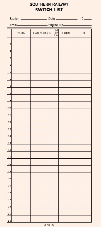
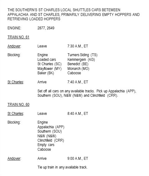
Recreated Southern switch list for my layout
That left me with switch lists. Switch lists are used on the prototype, either hand written or computer generated. They’re used mainly on local trains that will be setting off and picking up cars (not really needed for a train that’s not doing any switching). The switch list is specific to a train and tells the crew where each car in their train needs to go using the car’s initials (e.g., “SOU” and “LN”), car number, and some sort of destination designator. They often have additional information such as the car’s tonnage and load/empty status. The switch list is built by the conductor FROM any waybills or other routing information the conductor may have, so a crew doesn’t really need the individual waybills if they have a switch list.
On my last layout, I created a master list of every car on the layout and its destination (call it a “master switch list”), and I provided crews with blank switch lists they could use to build a tailored list for their train, much like a real conductor would do. However, I soon found that only the most die hard members of the crew would take the time to build their own list. For now, I’m building the switch lists for my crews and making it part of their starting paperwork along with the timetable and train order. I use the front side of the switch list for the outbound cars and the backside of the switch list for inbound cars, so crews merely have to flip it over instead of building it. I may revert to having crews build their own (or at least portions of it) in the future, but for now, I view the USE of a switch list as essential paperwork but the BUILDING of a switch list as tedium which I’m willing to endure but not push onto my operators.
To create the switch lists, I built forms in my favorite graphics program (yup, Microsoft PowerPoint) that I print out 3-per-page, front-and-back on thick tan paper and cut out. I found pictures of both Southern and L&N switch lists online (eBay is a great source for pics of old documents like this) and created railroad-specific switch lists for crews (L&N version below).
Destination Codes
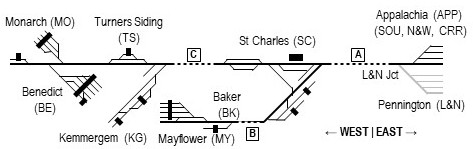
A key part of a switch list (and a waybill) is understanding the destination of the car. This can be done in many ways as long as each destination is unambiguous. Because a train usually performs switching within a town/station area, trains are typically “blocked” to group cars for each town/station–this makes it very helpful to include the town/station in the destination for each car. Once the car gets put on the correct train and taken to the correct town, it needs some sort of unique industry identifier, and for industries with more than one track, a unique track identifier. While you can use long-hand like “Mayflower / Mayflower Tipple / Empty track #3” as a destination, it gets a little tedious to write out, so like many other modelers, I use short-hand 2-letter codes for each town and a unique number for every track in the town. Here are my town codes for on-layout destinations:
SC – St Charles
BK – Baker
MY – Mayflower
TS – Turners Siding
KG – Kemmergem
MO – Monarch
BE – Benedict
I picked letters that not only make sense for the town name but are also hard to confuse with anything. For example, both “Mayflower” and “Monarch” codes start with an “M,” so I chose a second letter that would be hard to confuse with the other name (i.e., “Y” is found only in Mayflower and “O” only makes sense for Monarch).
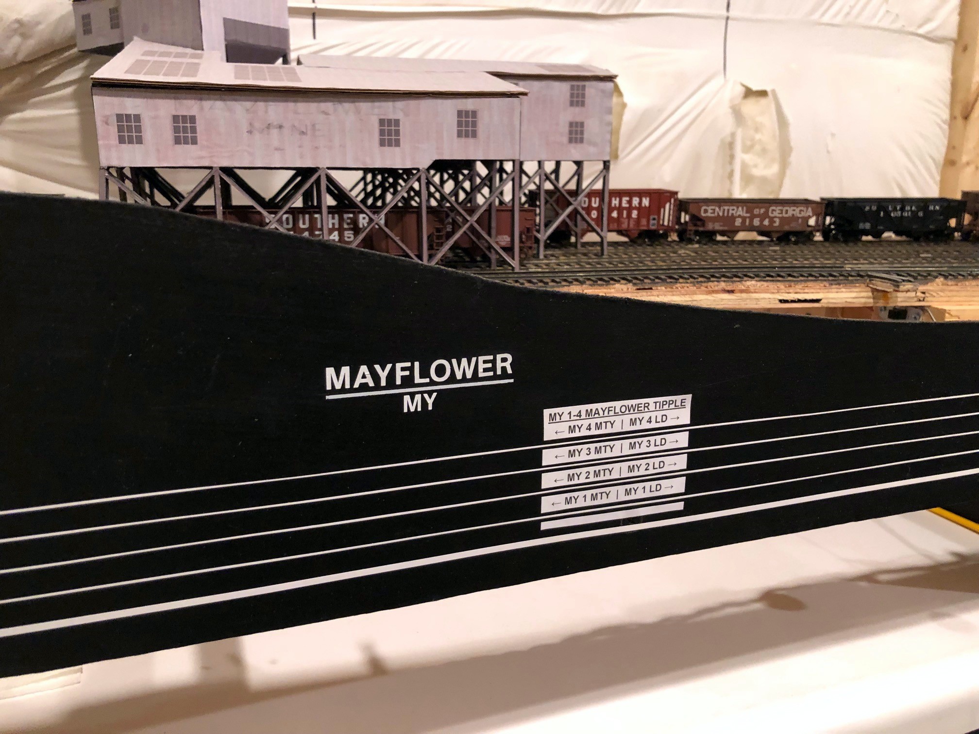
Track diagram and destination markings on the fascia at Mayflower
For the second part of the designator, I could have gone with a second letter/number for the industry and a third designator for the individual track within the industry. Instead, I opted to only use track designators since it still gets the job done and cuts out an extra symbol. So, for a town that had two industries with 3 tracks each, one industry would have tracks 1-3 and another industry would have tracks 4-6. For tracks with multiple industries on a single track, I use “4B,” “4C” etc. for each destination. For example, at the Mayflower tipple, I have a place to spot boxcars or flatcars bringing in material on part of tipple track 4, so this destination gets it’s own “4B” designator to differentiate it from the tipple. Tipple tracks on the prototype inherently have separate areas for “empties” and “loads”–because an operator can easily see if a hopper/gondola is empty or loaded, I didn’t include this in the destination code. I also created a unique track designator for ALL tracks that could be a destination for a car and not just fixed industries–for example, I sometimes use the end of the main at Mayflower as a place to spot a covered hopper, so I’ve designated the last 12 inches of the main as “track 5.” When looking at a switch list, each car bound for a destination on the layout will have a short-hand 3-letter destination code like “MY3”, or in the case of a track serving multiple spotting locations, “MY4B.”
I don’t expect operators to memorize these track numbers, so I place them on a track diagram on the layout fascia. Each town is clearly marked with its name and its 2-letter destination code. Each track is labeled near the turnout throw with its unique number. Each industry or destination spot is marked by a block at the intended spotting location containing its name and the associated track designator(s). In this way, an operator can arrive at a town, look at the fascia, and by checking the switch list know where each car in the train should go.
Track Chart
Most railroads also publish track charts for all their lines. The track chart contains useful information like grades and curvature, but it also includes a block diagram for each section of track with the town name and a diagram of all the tracks and their length–this diagram is often drawn in a blocky style using only 0, 45 and 90-degree lines. While crews on my layout don’t necessarily need to know grades and curvature, they do need to have a basic understanding of where towns are in relation to one another. For this, I drew up a simple little track chart of the entire layout for operators to use.
Simple track chart for my St Charles Branch layout
The track chart is laid out in “right = east” orientation and includes the town names (and short-hand designation) in the correct order. It also has a basic track diagram of each town, and I’ve depicted tipple and depot locations (depots are usually drawn on track charts, tipples are usually not). I’ve also included dashed lines for the hidden areas of the layout with letters that correspond to markings on the fascia to help crews better understand logically where their train is headed when they head out of the visible scene. The track diagram also helps them understand how to construct and block their train when heading west of St. Charles.
Blocking Instructions
Southern Blocking Instructions for layout crews
Speaking of blocking a train, prototype trains aren’t put together in random order but rather are assembled into “blocks” based on the destinations of the cars. Switching and local crews are typically required to block their trains in a certain manner to make them easier to handle at the next station or by the receiving crew, so I want to simulate this on the layout as well. Trains waiting in staging are already blocked by me before an operating session (you’re welcome), so the majority of the blocking for crews is for trains taking cars from the upper layout to staging. I could have just left the blocking at “Southern” and “L&N,” but I wanted to give crews a little more prototypical work to do. In addition to the online destination codes, I’ve got multiple destination codes for the Southern’s offline staging yard representing Appalachia, VA (pre-1965) or Andover, VA (post-1965). The loaders in the vicinity of St Charles loaded mainly two types of coal: raw coal for the huge Westmoreland transloader in Appalachia and clean coal bound directly for customers (routed geographically south of Appalachia/Andover) or to connections east of Appalachia/Andover with the N&W and Clinchfield, so all cars that aren’t L&N have a destination code APP, SOU, N&W or CRR to be used by crews to block their trains prior to returning to staging.
The Southern produced a periodic document called Freight Train Schedules and Blocking Instructions. This book has a page for every scheduled freight on the railroad describing how it should be blocked including engines, cars by destination, and caboose. I’ve created a similar document for my crews. In addition to blocking by destination, I’ve also included blocking instructions that place loaded cars on the head end of empty hopper trains and empty cars on the back end of loaded hopper trains, a common prototype practice to improve train handling on grades and curves. I also add a couple basic instructions for the crew to help them understand the train’s purpose and their chores a little better.
Part 3. Putting It All Together
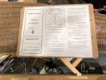
So, in summary, a crew on the St Charles Branch needs a timetable for basic train schedules and area instructions, a clearance card telling them how many train orders they have, at least one train order giving them clearance and specific instructions for their job that day, a switch list telling them where each car should go, a key for each town labeling destination tracks to match the switch list, blocking instructions to get cars ready for the return trip off the layout, and a track chart to help their brains understand the arrangement of towns and tracks. That sounds like a lot of paperwork, but it really isn’t. First, the “key” for each town is on the layout fascia, so they don’t have to carry it with them. Most of the other bits of paper can be combined into a single sheet. For each train, I build a single sheet that has the clearance card and train orders printed on the left, the train description and blocking instructions on the upper right, and the track chart in the lower right. Now, when you add the timetable and switch list, the operator only needs 3 physical sheets of paper. This is still a bit much to carry loose, so I provide each crew with a clipboard for their train. Clipped on the front is the sheet with clearance card/train order/blocking instructions/track chart. On top of that is the switch list. The timetable goes into a plastic sheet protector on the back for easy reference. Add a pencil and an uncoupling tool (attached by Velcro), hand them a throttle, and they’ve got everything needed to operate successfully on the railroad!
Single sheet for crews with clearance card, train order, blocking instructions, and track chartThe one-page timetable fits neatly in a plastic pocket on the back of a clipboard
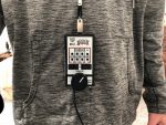
One final note, when using model paperwork, operators need a convenient place to set things down or else they’ll either leave it behind (bad) or set it on top of the layout (more bad). For those who’ve been keeping up with the layout’s progress, you’ll remember the fascia pockets I build around the layout between the staging and lower levels–this is why they exist. No matter where an operator is in the layout room, they’re never more than about an arm’s length away from a clipboard pocket. How about the throttles? When an operator is handling a train solo, they need to be able to quickly set the throttle down to interact with the paperwork. While there are throttle pockets all around the layout, it’s even better if the operator can just keep the throttle with them. This is where the throttle lanyards that allow an operator to just drop the throttle and let it dangle from their neck come in real handy–this is perhaps the best $1.50 solution to a $25.00 problem on the layout so far!
Conclusion
I’ve taken a little more time on this post because I want it to serve as a more thorough article for those looking for ideas on realistic model railroad operations. I will never claim to have “THE solution,” and there are definitely pluses and minuses to my methods. I do believe this method, though, strikes a good balance that gives the die hard prototype enthusiast or ex-railroader enough sufficiently realistic paperwork to make them feel at home while being limited and simple enough to avoid intimidating newbies or weighing crews down with tedious tasks that only a small percentage of people find fun. While I will continue to refine my operations as the layout evolves, this method definitely meets my goals and needs for the short-term. I’m always learning, so please feel free to post your critiques, feedback and better ideas in the comments section! I’ve also included some jpegs of the blank forms below–feel free to use these for your own personal use. The easiest way to “fill them out” is to copy the images into MS PowerPoint or similar program and create a text box on top of the image.
Clearance card showing how many orders the crew has
An example of my model Southern Form 19 train order
An example of my model L&N Form 31 train order
Southern Blocking Instructions for layout crews
Single sheet for crews with clearance card, train order, blocking instructions, and track chart
My blank Clearance Card
My blank Southern Form 19
My blank L&N Form 31
A train order awaiting pick-up at St Charles
Everything the St Charles Local needs to operate on the layout
The one-page timetable fits neatly in a plastic pocket on the back of a clipboard
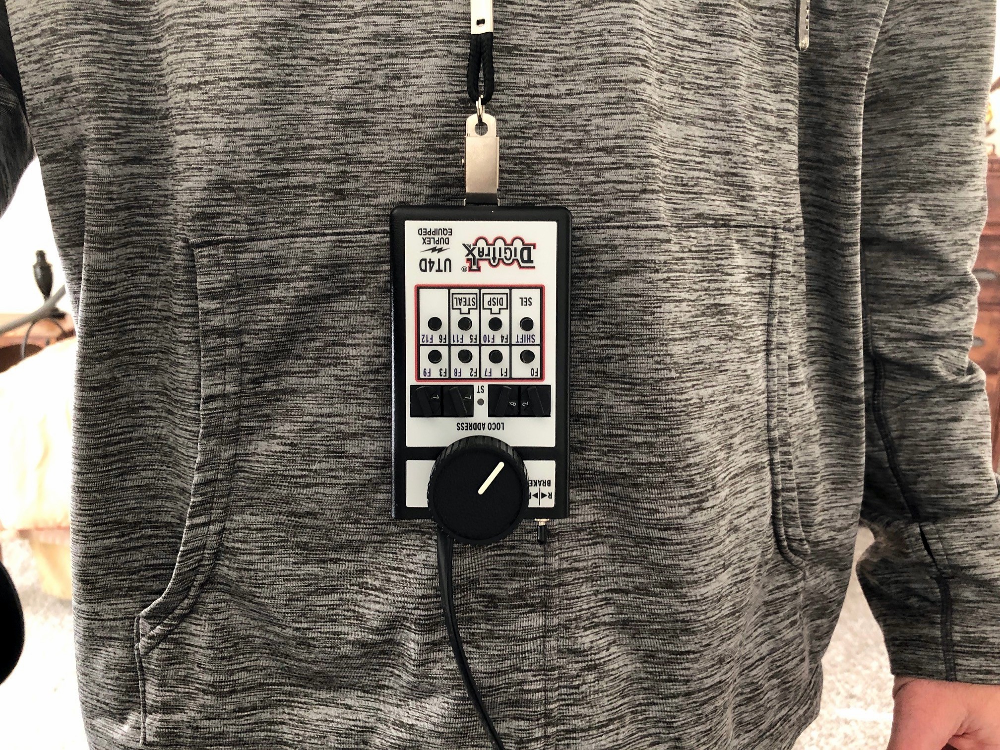
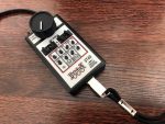
I’m continuing to capture little projects on the layout as I think about them. I bought a “spare” Digitrax UT4D utility throttle recently and was reminded of the modification I’ve done to all my UT4s to make them more user friendly. I use the UT4D 2-way radio throttles because they’re light, very easy to use, and the wireless makes them very convenient to use anywhere on the layout. Despite this convenience, there’s still one major problem with the UT4 (or any walk-around throttle for that matter)–where do you set it when you’re not using it? This is not a problem when you’re done with your train as I’ve got plenty of throttle pockets along the fascia in which to stash them and plug them in to keep the batteries from draining. But what do you do with the throttle when you need your hands for other chores like uncoupling and paperwork? This is a major consideration for a switching oriented layout like the St Charles Branch.
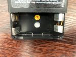
On my last layout, I came up with the idea of attaching a simple anchor for a clip-style lanyard. It does require drilling a couple holes into your throttle, but it’s only through a narrow part of the plastic casing and into the battery compartment, so it’s not a threat to the throttle’s electronics. The anchor is made from .025″ steel music wire which you can pick up at most hobby stores. Lanyards come in many styles, but I use the lanyards with the “bulldog clip” that doesn’t swivel and provides a very easy pinch mechanism to attach and release the throttle such as the ones in this link (yes, I get a little commission if you use this link, and it doesn’t cost you anything extra to use this link–thank you).
Here are the rest of the steps:
REMOVE THE 9V BATTERY FROM THE UT4!!!
Cut a piece of .025″ steel wire about 2″ long
Bend into a squared-off “U” with the bottom about 1/2″ wide (just wide enough for the lanyard clip with about 1/32″ of slack) and each side about 3/4″ long
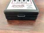
Mark the bottom of the UT4 throttle case for drill holes–make them the width of the U and centered within the “groove” of the plastic
Drill 2 holes into the case–use a drill bit that’s slightly oversized so the wire slides freely without rattling
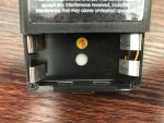
Insert the wire “U” into the case and attach a lanyard to the bottom of the “U”
Push the “U” into the case as far as it will go and then back off just slightly (“U” extends approximately 1/8″ from bottom of throttle case)
Bend the ends of the “U” that are inside the case outward to mark where the bends need to be
Remove the lanyard, push the “U” as far as it will go into the case and bend the ends inside the case with needle-nosed pliers until they are parallel with the case bottom
Extend the “U” outside the case then reinsert 9V battery, pushing it up against the top (antenna side) of the throttle as far as it will go
You should now have a clip anchor that retracts into the little groove when the throttle is set down on top of it that extends just enough to allow a lanyard to attach when picked up. It doesn’t get in the way of anything if an operator chooses not to use a lanyard, and it provides a secure way to let the throttle dangle when not needed. I’ve been using these mechanisms for years and have never had a catastrophic throttle drop (your results may vary ;-). Similar techniques may work on other throttles as well, though I’ve only tried it on the UT4D.
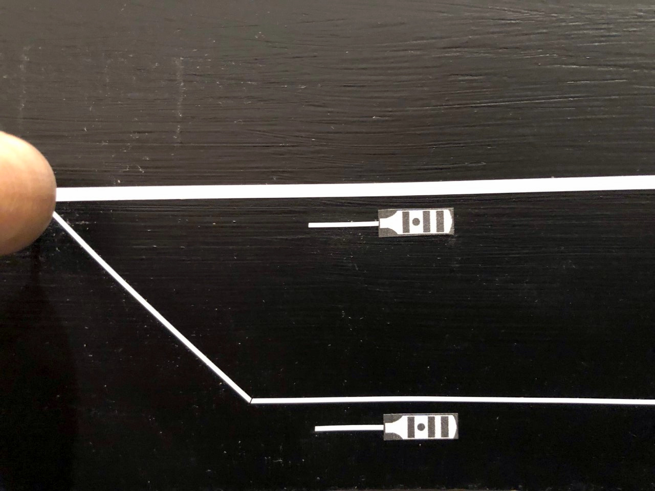
A couple of Southern-style whistle posts on the fascia track chart
I thought I’d share a little addition to the fascia–Southern whistle posts. I never thought about this on my last layout because none of my locomotives were sound equipped. Now that I’m moving toward sound, I wanted a way to tell crews when they need to sound the horn for grade crossings. On the prototype, posts are set up on either side of a grade crossing to give the crew enough time to sound off their loooong, loooong, short, looooooooong blast of the whistle or horn. While most railroads used a white sign with a prominent “W” for this purpose, the Southern used a vertically elongated white sign with a stripe, a stripe, a dot, and a stripe (for long, long, short, long). I decided I wanted my posts to be Southern-esque, so I created a simple black-and-white version from basic shapes in MS PowerPoint, sized them to about 1/2″ high, and printed them on a label sheet.
I cut them out and placed them about 15-18″ from the sites of future grade crossings (I have no roads modeled yet) which gives crews about 4-5 seconds of warning at 10 scale MPH, probably about right for the areas where these grade crossings reside. After placing the whistle post stickers on the right side of the track diagram (making them horizontal), I added a little 1/2″ piece of 1/32″ white graphics tape representing the post for the sign to ensure operators can tell which direction the sign is pointing. Once I have scenery, I’ll add some real scale whistle posts trackside, but for now, these will give crews one more prototypical thing to remember while operating their trains.
Lower level fascia complete and awaiting a few labelsPush rods can indeed be used for distant switches (48″ here) if properly guided and reinforced
This week’s project was completing the fascia for the lower level. I love the look of the curved black fascia and track diagrams. I’ve detailed fascia elsewhere, so I’ll stick to what’s unique here. While the switch mechanisms can be partially installed prior to fascia, it takes the facia being in-place to install the manual switch control knobs and push rods. While most of the mechanisms were pretty basic, there are three switches more than 30″ from the fascia on the “RR east” end of St Charles wye where the tracks emerge from the helix and staging. I wasn’t sure if I’d be able to use the push rods for long distances, especially since two of the switches are beyond 36″, the length of the .062″ steel rods I use. The trick with the push rods is the longer they are, the more they tend to flex and bend (and, in turn, not throw your switch mechanisms). This can be partially rectified by using additional brass tube guides in wooden blocks along the rod’s path, about every 12-15″ or so. That was good enough for the first mechanism that was <36″ from the fascia.
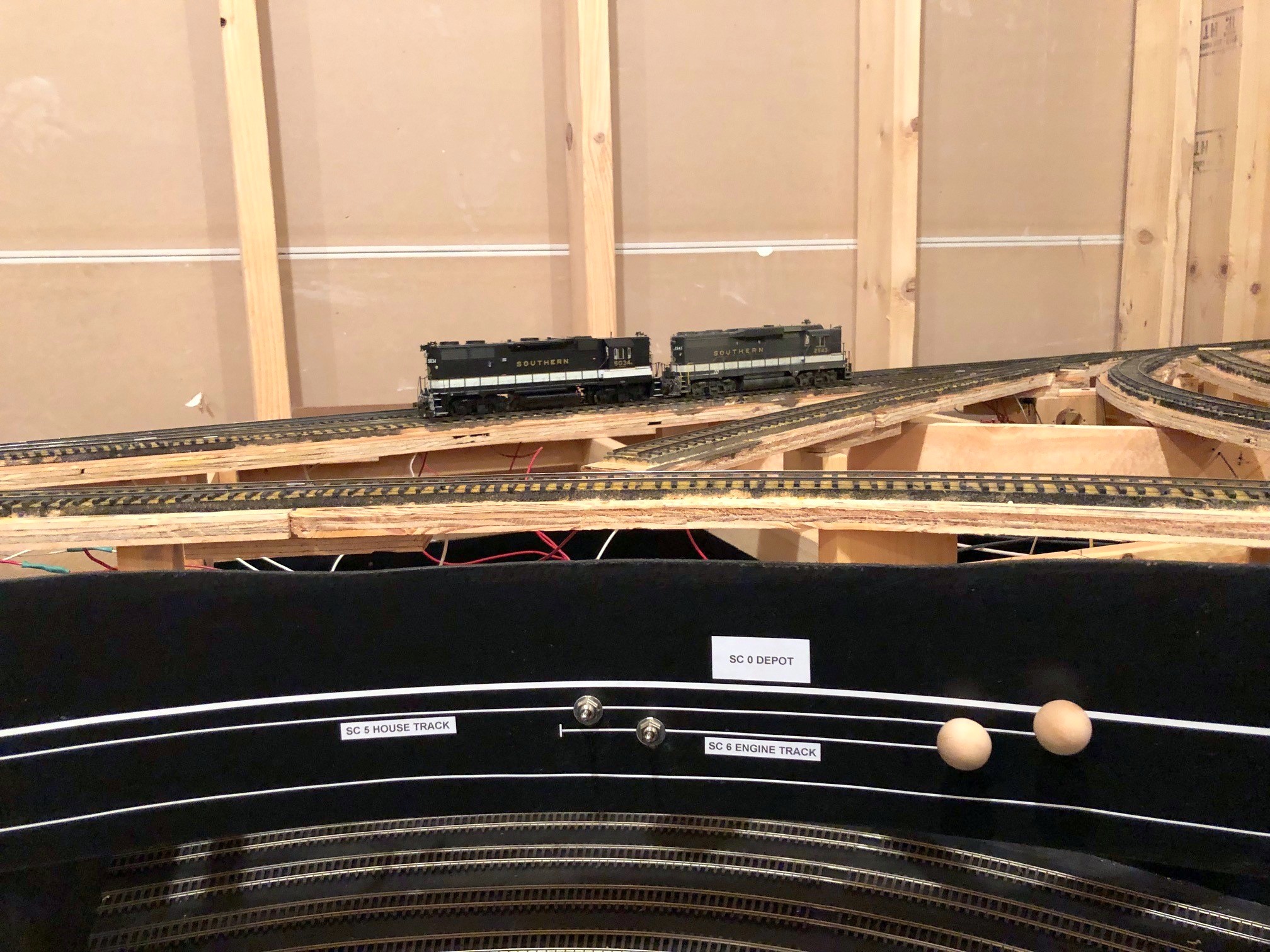
St Charles wye has two insulated tracks where engines might tie up
For the longer rods, I decided to try connecting 2 steel rods using a 6″ piece of 3/32″ brass tubing and Gorilla Glue. I use the Gorilla Glue to attach the wooden knobs to the steel rods, so I know it’s got at least SOME game with metal. Since these rods will be hidden by scenery, I decided not to trust glue alone, so I lightly bent both the tube and steel wire about 1″ from the end of the tube on both sides–if there’s one thing I’ve learned, even a slightly bent .062″ wire does NOT want to pull through a 3/32″ piece of brass tube! Once I added the bends, the mechanism is solid as a rock! I’ve now verified that the manual push-rod controls are viable to at least 48″ from the fascia–not bad at all, and all remaining switch controls should be well under this length.
Another unique feature of the St Charles fascia is the addition of two SPST toggle switches that isolate two of the tracks from the wiring bus. A while ago, I detailed how I did something similar for my staging tracks so I could easily silence sound locomotives when they’re not actively involved in the operations. St Charles was often home to a mine run, so the pair of mine-run engines hung out on either the “house track” or aptly named “engine track” adjacent to the depot. Since these are the only tracks on the levels with scenery where I anticipate parking locomotives, I decided to give them the same insulation and toggle setup as the staging tracks. While I will likely rarely use these, I figured it’s SO much simpler to add them now than decide I need them after-the-fact.