Layout wiring on the St. Charles Branch is simple yet very robust using common household wiring supplies. First, I’ve divided the layout into six blocks: four “main” blocks (1. Staging, 2. St. Charles, 3. Mayflower, 4. Upper Deck), and two reversing sections (1R. Staging loop, 2R. St. Charles Wye). Even though I don’t have a power block distribution circuit yet (like a PSX4), I’m wiring the layout for that eventuality and just tying all the blocks together at the command station as an interim.
The bus wiring for each block is copper Romex wiring. . . that’s right, Romex, the 14 AWG copper wire you use to wire household sockets and light fixtures. It’s overkill, but it’s easy to find, comes in long lengths, and the current loss for DCC applications is pretty much zero. I strip the outer sheathing, remove the bare ground wire, and use the black and white wires. I run them under the track through holes in the benchwork separated by about 2.5″. Lesson learned: if running the bus for two blocks side-by-side, make sure you label each about every other piece of wood to avoid cross-wiring blocks later.
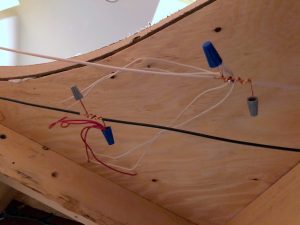
I drop feeders at least every 5 feet, so on every 2-5 feet of bus wiring, I’ll strip off about 1″ of insulation and make a “pigtail” if you will using a length of 4″ of the bare copper wire (Romex ground wire) wrapped tighly around the bus core about 3 turns and soldered. I leave about 1″ of copper sticking off either end and cap it with a wire nut. I separate the pigtails for the white and black wires by about 4-6″ to avoid accidental contact of exposed wire.
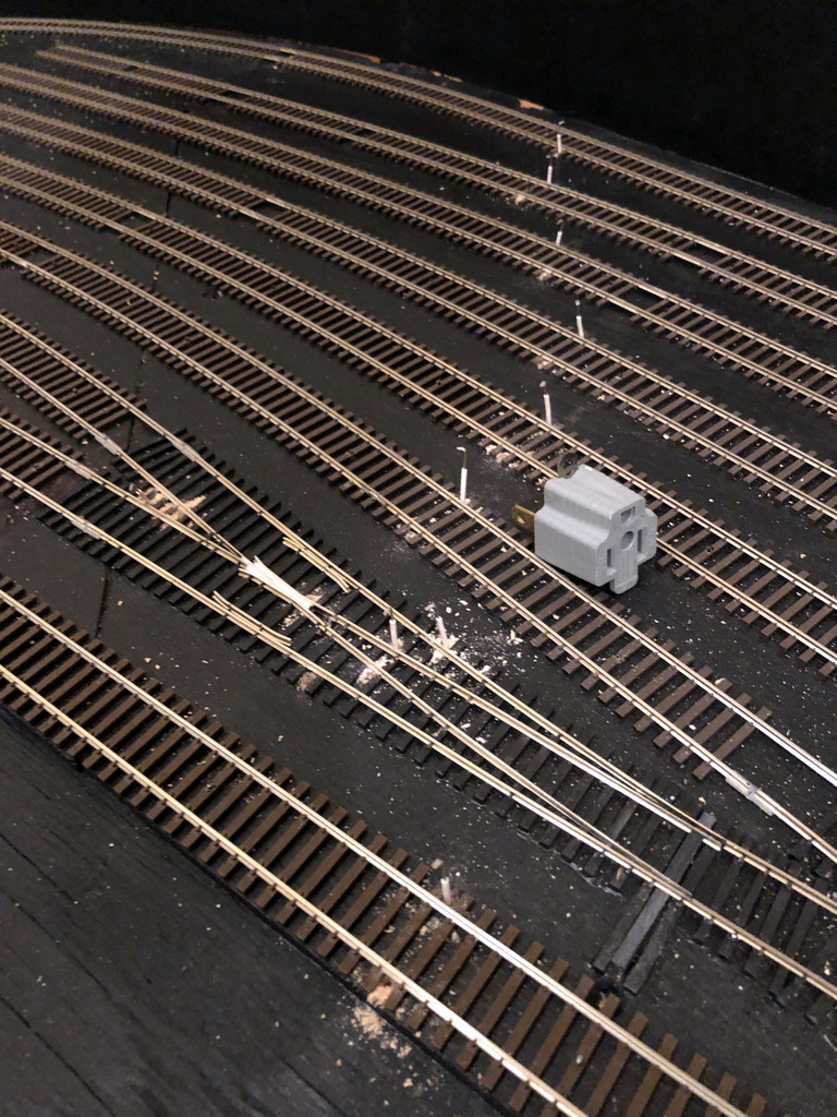
Finally, the feeders. As mentioned, I try to drop them every 3-5 feet of rail. For bulletproof operation, every single rail on the layout is directly connected to the bus either through its own feeder or a single soldered joint to the rail next to it that’s connected to a feeder (no trusting rail joiners to carry current and signal). I drill the holes first, then drop pieces of 18 guage stranded wire through to connect to the bus. You’ll notice in the picture above the layout the little gray plug. I use this to mark the location of the pigtail under the layout so I can accurately cut the feeders to length, leaving about 1.5-2″ extra length to account for vertical distance through the subroadbed and some wiggle room for orienting the feeder to fit into the pigtail. Because I hand-lay my switches, I need a LOT of extra feeders for the point rails and frogs (connected to switches under the layout).
To make sure I hit all the holes, I leave the sawdust from drilling them in-place until all feeders are in. I also work one color at at time; white for one rail, red for the other. Once all the feeders of one color are in place, I’ll tin them with solder and solder each to the rail. Under the layout, I’ll gather together 2-3 feeders, twist them together, and tie them to the pigtail using a common wire nut (size depending on the number of wires being tied together). A little tug ensures they’re solidly in-place.
I’ve found this method creates rock-solid wiring that’s easy to modify and troubleshoot–just disconnect and reconnect the wire nuts as needed. This method also works perfectly with Digitrax DCC which prides itself on picking a slower data rate that works well with non-high-speed wiring. If using on a different system, I recommend doing some testing first.