Everyone with a layout has that “special” locomotive. No, not your favorite one with the custom paint and weathering or the one with the beautiful sound system. You know, it’s the one that despite every effort you’ve made to make sure there’s nothing obstructing free movement, there’s nothing dragging, and all the wheels are in perfect gauge, still manages to find ways to fail to stay on the rails where 100s of others have succeeded before. . . that kind of special. These locomotives serve a wonderful purpose, but I’ll get to that later.
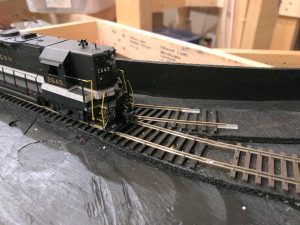
My special locomotive is Southern GP35 2649. It’s a kitbashed Athearn model with a high nose and Alco-style truck sideframes. There’s nothing remarkable about the drive system, wiring, or anything else–if anything, it might be a tad on the light side.
For the last month, I’ve been running trains on my staging level. It’s been a great exercise in working out the kinks in the trackwork and power, getting re-acquainted with my DCC system and JMRI DecoderPro, and just enjoying watching some trains run. I’ve gotten to the point where I could back a 34-car train of empty hoppers with 3 units shoving all the way around the layout and through all three of the reversing loop tracks–I was pretty proud of my work! Then came the Special. . .
My “special” locomotive, Southern GP35 2649, next to the track joint that it alone didn’t like. Yes, there’s a solder blob there, but now that it’s working for 2649, I don’t dare touch it!
Southern 2649 never got a lot of running time on my last layout as it was one of the last locomotives to make it to running shape before I had to tear things down. I decided to break it in a bit more today by running it in loops around the staging level. First long-hood forward–no problem, negotiated everything like a pro for 30 minutes! Ok, let’s reverse direction–looking good, going through the last switch. . . on the ground. Hmm. put it back on the rails, backed up, through the last switch. . . on the ground again. I repeated this process several times and determined it wasn’t the switch, but it was running over the outside rail right at the transition between hand-laid switch track and flex track. I felt the track joint–smooth as it could be. I checked the gauge–spot on. I re-soldered the joint anyway. . . on the ground. I could propel the engine over the spot by hand with no issues, but as soon as it was under its own power, it would climb right over the rail–infuriating!
I removed the brake cylinder piping on the front truck to make sure it wasn’t catching. . . on the ground. I took off the truck sideframes and smoothed out the backs of the brake cylinders to make sure they weren’t catching. . . on the ground. I finally went back to the soldering iron and re-did the entire track joint, using a screwdriver to lift up the rail a bit and a pair of pliers to push one rail further in to provide a little more curve to the rail before hitting the joint. Let’s see, will 2649 like it? . . . I stood there, looking like an expectant father who’s watched his kid fall 100 times learning to ride a bike and thinking “maybe, just maybe this time will be the one!”
Lo and behold, 2649 made it through! I watched proudly as it circled the layout like a champ, passing yard after yard of flex track, across the last switch before making it back to the starting point, and then “bah, dah, dah, dah, dah, dah”. . . the telltale sound of wheels on ties. Sigh. At least this time it was an easy diagnosis, a spike I had put on top of a rail joiner to hold it more securely in place was just a little too high. Yes, every other wheel on the layout had passed this joint 1,000s of times without incident, but alas, 2649 can find any flaw!
And that’s why I’m happy to have the very special 2649 on the roster. With 24″ radius curves, S-curves through switch ladders, and even some #4 curved turnouts, the track work on this layout needs to be flawless to be reliable. And it’s not flawless until 2649 says it’s flawless! As frustrating as its finicky nature may be, 2649 makes me a better modeler, and that’s what makes it truly special.
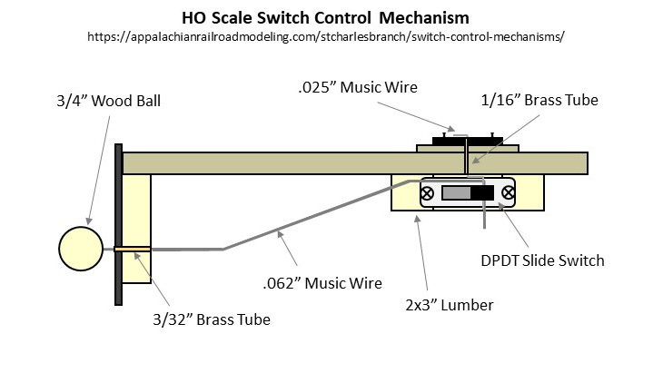
I’m taking a pause on construction to work all the bugs out of the staging level before building on top of it, so I thought I’d share my method of building manual switch control mechanisms that operate from the fascia. I developed these mechanisms for my last layout, and since they proved to work so reliably, I’m doing the same on my current layout. What I like about these mechanisms is they’re rock-solid, easy to use, and unlike alternatives such as Caboose Industries ground throws, they keep fingers away from the scenicked area of the layout. As an added bonus, using a DPDT slide switch as the “guts” not only gives it a “snap”, but it makes it easy to power frogs and LED indicators if you want them.
The Design
The figure shows most of the relevant parts of the mechanism. It’s essentially a DPDT slide switch mounted to a piece of 2×3″ lumber for the mechanism, a piece of .062″ music wire and a 3/4″ round wood ball for the control arm, a piece of .025″ music wire for the throw, and pieces of 3/32″ and 1/16″ brass tubing where the music wire needs to go through wood.
Making the Parts
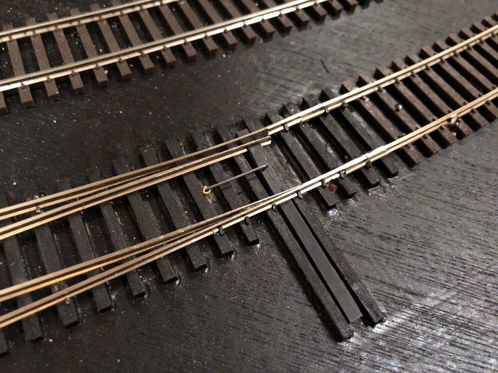
The top portion of the throw bell crank made from music wire
I create the throw first by drilling a snug hole for the piece of 1/16″ tubing about 5/8″ from the throw bar of the switch. I normally drill this dead center between the rails on the frog side of the throw, but if you have benchwork interfering below, you can put this anywhere along the throw bar on either side. I’ve found 5/8″ distance works well with the DPDT switches I use–anything shorter and it won’t throw far enough; anything longer, and the wire is not stiff enough for a reliable throw. I cut a piece of 1/16″ brass tubing just long enough to reach the bottom of the subroadbed while remaining just a fuzz above the ties on top and gently tap it in with a hammer. Next I drill a hole large enough for the .025″ music wire in the throw bar adjacent to the hole for the tubing. I cut a piece of .025″ music wire about 4-5″ long and bend one end to fit perfectly into the throw bar (clipping it to avoid dragging under the throw bar) and dropping into the tube. While holding down the top part of the wire, I reach underneath and bend the other end of the wire as tight as I can by hand opposite the direction of the throw and perpendicular to where the control arm will go–it doesn’t matter that the bell crank is in line with the throw; it matters that it’s perpendicular to the direction the control arm will need to move. Finally, I use a pair of needle-nosed pliers to bend the wire toward the ground about 3/16″ from where it exits the bottom of the tube. The bell crank is now complete, and you should be able to easily throw the switch by moving the bottom of the wire back and forth.
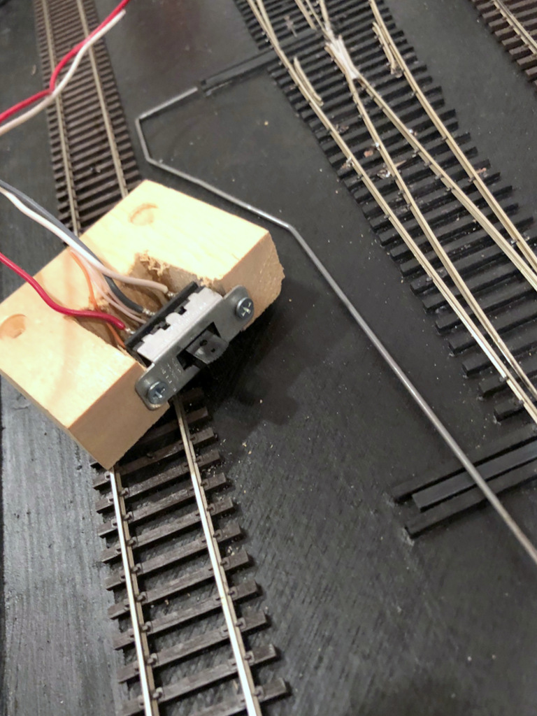
Switch mechanism ready for mounting sitting next to its control-arm wire
Next I build the mechanism. First I solder feeders onto the DPDT switch–I use red and white for the connections to the track bus and gray or blue in the center for the connection to the frog. Next I cut a piece of 2×3″ lumber about 2 1/2″ long (you can use any size, but smaller will be more delicate, and larger will be tougher to fit around benchwork). Then I a notch about 1″ deep just wide enough for the DPDT switch to fit. At this point I designate a “top” of the mechanism and install the DPDT switch with small wood screws. With the mechanism placed between the throw and the frog, the feeders should be REVERSED from the normal orientation of your track bus. In other words, my track bus is normally oriented red/black-front, white-back, so I install my DPDT switch with the white feeder in front. Finally, I drill two holes through the slide portion of the DPDT switch, one just big enough for the .062″ control wire and the other closer to the tip of the switch for the .025″ throw wire. I’ve found drilling both holes with the smaller bit and then enlarging one prevents the plastic from breaking. I put a little countersink into the top of the holes by spinning an X-Acto knife in them to make it easier to insert the wires. NOTE: my switches are hollow inside which makes it a bit of a pain to insert the wires sometimes–it just takes a litte patience. I finish by drilling and countersinking two holes where I want the screws for mounting it to the layout will go.
The next step is the control arm. First I decide where I want the control knob on the fascia. For me, I use a simple track diagram on the fascia with switches drawn in (more on this in a later post), so I draw the diagram first, then drill the hole that will tightly fit the 3/32″ brass tube perpendicular to the ground and aimed toward the end of the throw crank under the layout. Then I cut the 3/32″ brass tubing to fit just through the fascia and 2×3″ board edging the layout. In some spots, there is no board, so I’ll glue a square piece of 2×3″ lumber behind the fascia to ensure adequate support. There might also be other lumber between the fascia and the switch. If its a fairly short distance (<12″), I’ll drill a 5/8″ hole where the control arm will go through. If it’s a longer distance, I’ll drill a second hole for 3/32″ tubing in line with the first–this isn’t tough to do if you take a piece of straight .062″ wire, push it through the fascia tube and mark where it hits the intervening lumber. The straigher you make these two tubes, the smoother the mechanism will be. Finally, I bend a control arm. Starting at the switch end, I bend the last 1″ 90 degrees toward the ground where it will go through the slide switch, then I make a slight bend downward about 1″ from the 90 degree bend toward the fascia hole, then another bend about 1 1/2″ from where it will go through the 3/32″ tubing. The sharpness of the anlged portion depends on how much room you have between the switch and fascia and how far down on the fascia your control knob will be. The shallower the bends, the more solid and reliable the mechanism will be. I cut it with a Dremel tool and cutoff disk (enjoy the fireworks!) so it will protrude about 1 1/2″ through the fascia and file the burrs off the end.
Mounting the Mechanism
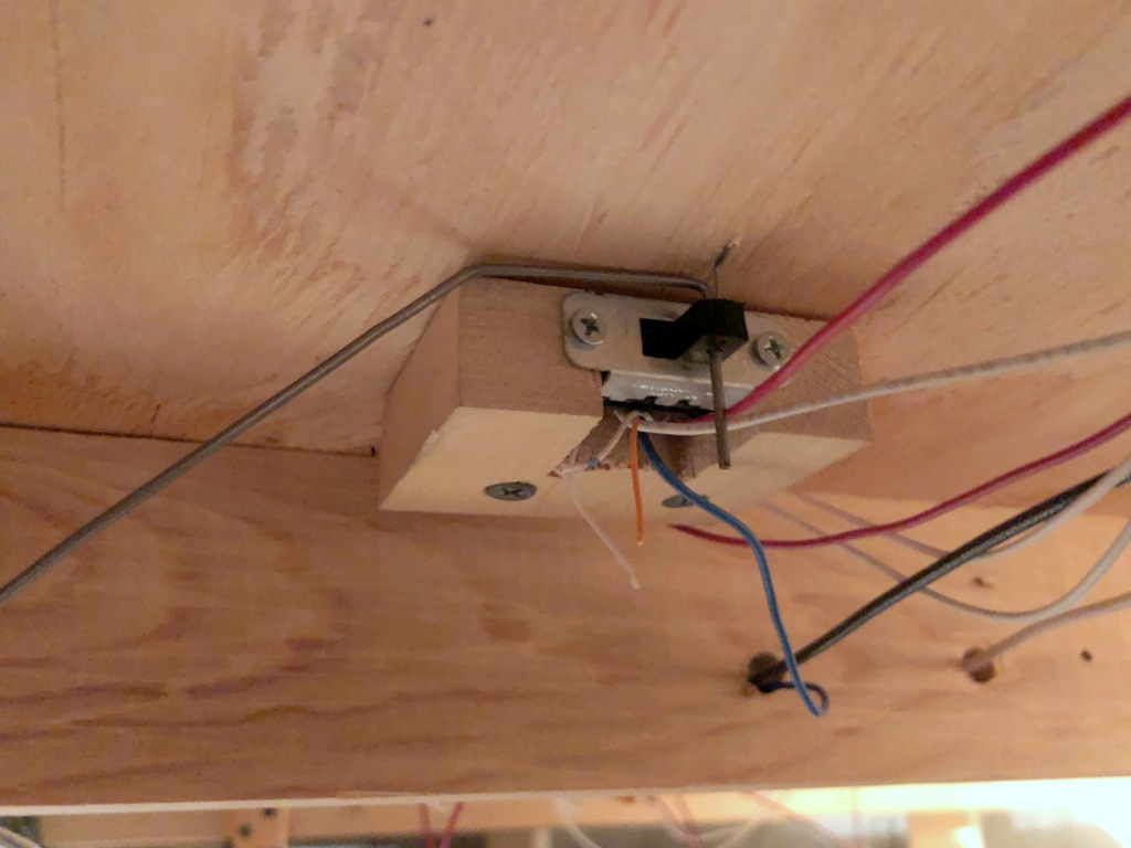
Here’s what a completed installation looks like under the layout
This part is straightforward, but it can be tricky and sometimes frustrating to get the switch is exactly the right spot–it requires some experience and skill to get it right, and that experience and skill requires some misfires and mistakes to gain. I first install two 1 1/4″ drywall screws into the mechanism mounting holes with about 3/32″ of the tip sticking through–this gives a way for the mechanism to grab the subroadbed a little while you’re placing it. Then I insert the control arm through the DPDT switch and run the other end through the 3/32″ tube(s) and out the fascia. Next I place the mechanism onto the .025″ bell crank (this part can be tricky and frustrating if the wire and holes don’t line up well). Once everything is inserted, I place the DPDT slide in the middle position and do the same with the throw topside–with both of these in the middle position and the DPDT slide direction in line with the control arm, I press the mechanism into the subroadbed and hold it in place. While holding the mechanism in place under the layout, I’ll try work the mechanism to ensure it throws snugly to both sides. This is a matter of trial-and-error, but once I’m satisfied, I’ll put one of the screws into the subroadbed. Inevitably, it will leave a gap between the mechanism and subroadbed because I wasn’t able to pre-drill the hole. . . no worries. Then I’ll start the second screw, go back to the first and back it out then put it back in to cinch it up, then do the same to the second. If all has gone well, the control arm will easily push the slide switch to both limits, and the throw will push the point rails snugly to each stock rail. If not, back out the screws and try again!
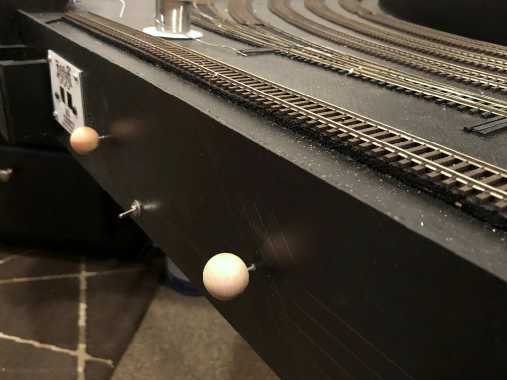
How the completed switch mechanism looks on the fascia
Once I’m satisfied that the mechanism is where it needs to be, and everything is operating smoothly, the last step is to install the control knob. I first push the control arm wire in, then cut it off with the Dremel about 5/8″ from the fascia and file smooth. Then I drill a hole straight into and about 2/3 of the way through the round wood ball. After moistening the wire and ball, I add a drop of Gorilla Glue to the wire and place the wood ball onto the wire. It should be tight enough that you have to twist it on. I like for the control knob to sit about 3/16″ from the fascia when the knob is pushed in. Work the switch a few times while the glue is wet to make sure it feels right where you’ve placed it, then let it dry. Connect the feeder wires to the track bus and the third wire to the frog and the switch mechanism is complete! While it sounds like a lot of steps, if you mass produce the 2/3″ mounts and DPDT switches with pre-drilled holes and wires pre-soldered, you can install 3-5 mechanisms in an hour.
The top portion of the throw bell crank made from music wire
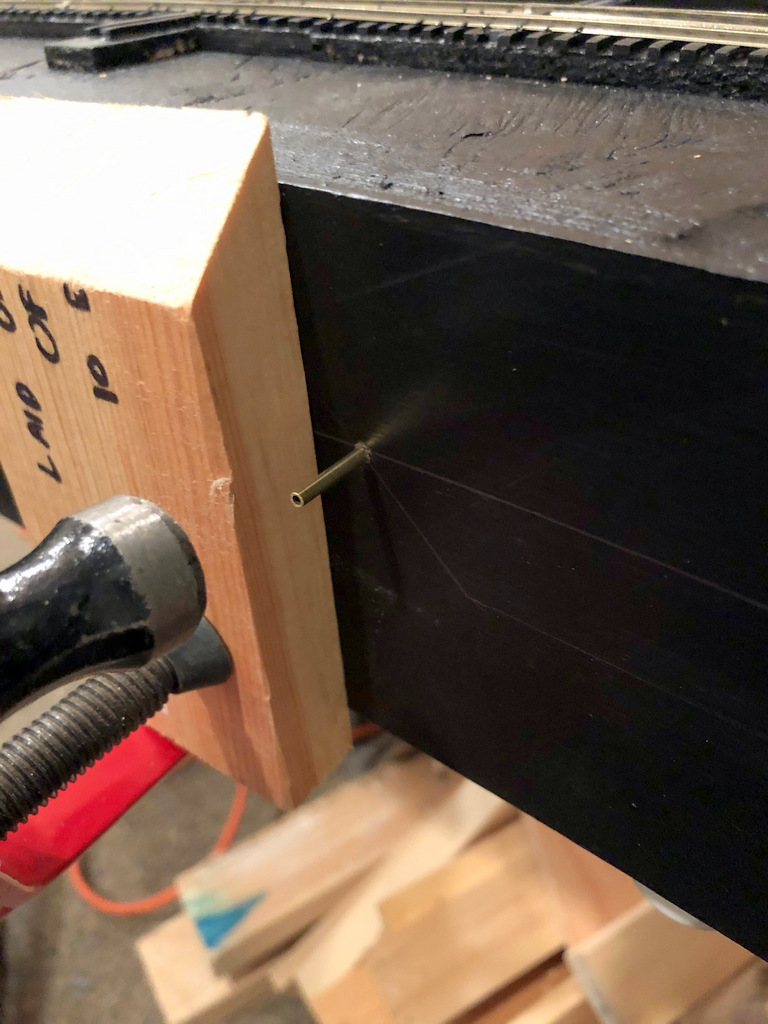
Hammering the 3/32″ brass tube through the fascia–the tubing should fit snugly. the board and clamp are holding a piece of 2×3″ lumber onto the back side of the fascia to add stability.
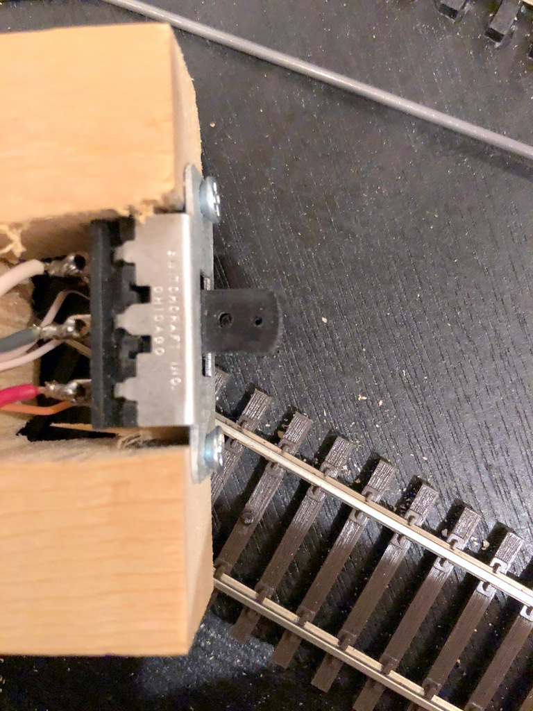
Two holes drilled into the DPDT switch lever, one for the control arm and one for the bell crank
Switch mechanism ready for mounting sitting next to its control-arm wire
Here’s what a completed installation looks like under the layout
How the completed switch mechanism looks on the fascia