Monthly Archives: July 2023

Simple Paintbrush Handbrakes for Spotting Cars

Paint brush handbrake holding empties above the tipple
Handbrakes in action holding empties securely above the Mayflower tipple

The ability to set handbrakes to keep cuts of cars in place on a grade is a crucial part of railroading, and a model railroad is no different, especially one set in the Appalachians. I’ve covered my technique for building manually deployable handbrakes via a retractable wire between the rails (article here), but the controllable brakes are complicated to make and install, so I reserve them for areas where I’ll be holding long cuts of cars on a steep grade or for where I need to hold a car for a while and then let it loose for some “gravity assisted switching.” But there are several dozen spots on the layout where I’ll need to spot small cuts of cars on slight grades, so for these areas, I wanted something simpler. I also like free-rolling cars, so tricks like putting a tiny spring on the end of one of the axles was also off the table–it needed to be something in the track. Enter the cheap plastic paintbrush! Each paintbrush handbrake costs just cents to make, and I can easily make and install a dozen in under an hour.

I picked up a box of 100 inexpensive plastic paintbrushes a couple years ago when the local Christian bookstore was having a big sale. I didn’t know how I would use them, so I put them away for a rainy day. That day came when I was playing around with different ideas for holding cars in place. It needed to be something I could roll cars and locomotives across easily without derailing or causing too much friction that would also be sturdy enough to hold a car when spotted over the brake. I first tried two methods that I’ve seen work for others. The first is a little dot of CA on top of the rail, but many of my spotting points were just too steep for this. Next I tried little lengths of fishing line mounted between the rails–these are good because they’re tough to see and work pretty well, but they make a noticeable “plink” every time they clear an axle or a hopper bay… in sections of the yard where I had several in a row, it sounded like a tiny music box playing a discordant tune!

Paint brush handbrake cheap brushes
The starting point for handbrakes are inexpensive plastic paintbrushes from an art or hobby store

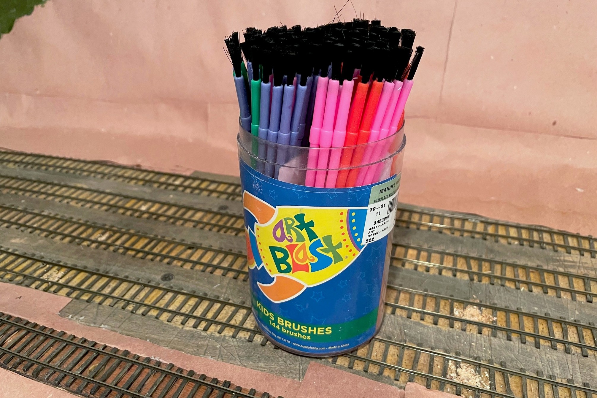
Then I remembered the brushes. The plastic bristles are pliable enough to give when trains are moved across them but stiff enough to hold a car when no other force is exerted. They could also be trimmed both in height and in density using a pair of scissors. They are certainly more noticeable than the fishing line or CA dots, but my hope is they’ll blend right into dirty coal-covered tracks, and those that don’t blend in can be painted to look like weeds. Even with nothing to disguise them, I find they don’t draw the eye much anyway.

Paint brush handbrake holes
Step 1 is to locate where you need the brakes and drill a hole–the hole is offset to avoid wear-and-tear on air hoses

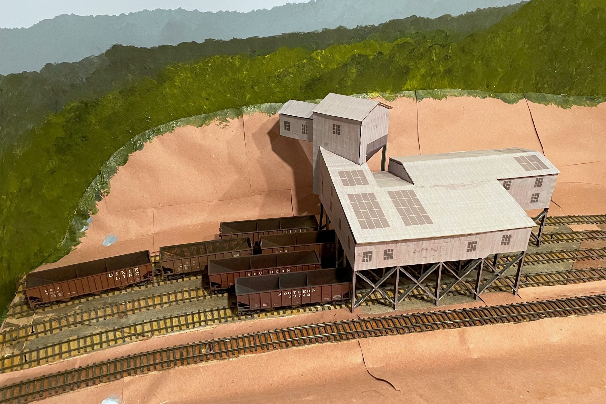
The first step is to locate where you want to install the “brake.” Figure out where you want the car or cut of cars to sit, then mark the spot where the most downgrade axle will sit–this is where you want the brake. In some cases, like the end of a track, you can mark the spot of the downgrade axle of the upper truck–I use this at the end of stub tracks where I need all the room I can get. For tipple tracks, I find it useful to have up to four handbrakes per track. One at the uphill end of the empty track to hold a full cut of empties, one just above the tipple to hold a shorter string of empties, one just below the tipple to hold a shorter string of loads, and one just before the fouling point of the downhill switch to hold a longer string of loads (or any “gotaways”).

PPaint brush handbrake trimmed down
Starting and ending points with the brushes, just a little off the top and thinned down with scissors
Paint brush handbrake ready to install
The finished “brake” ready to install between the rails


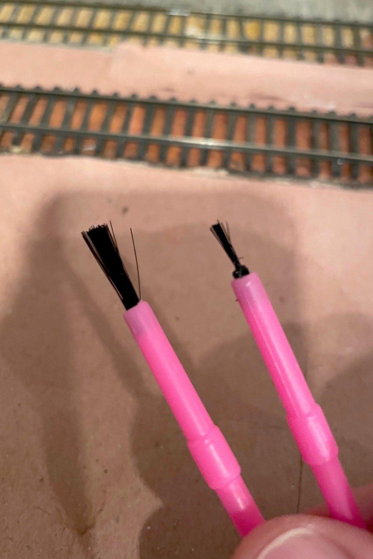
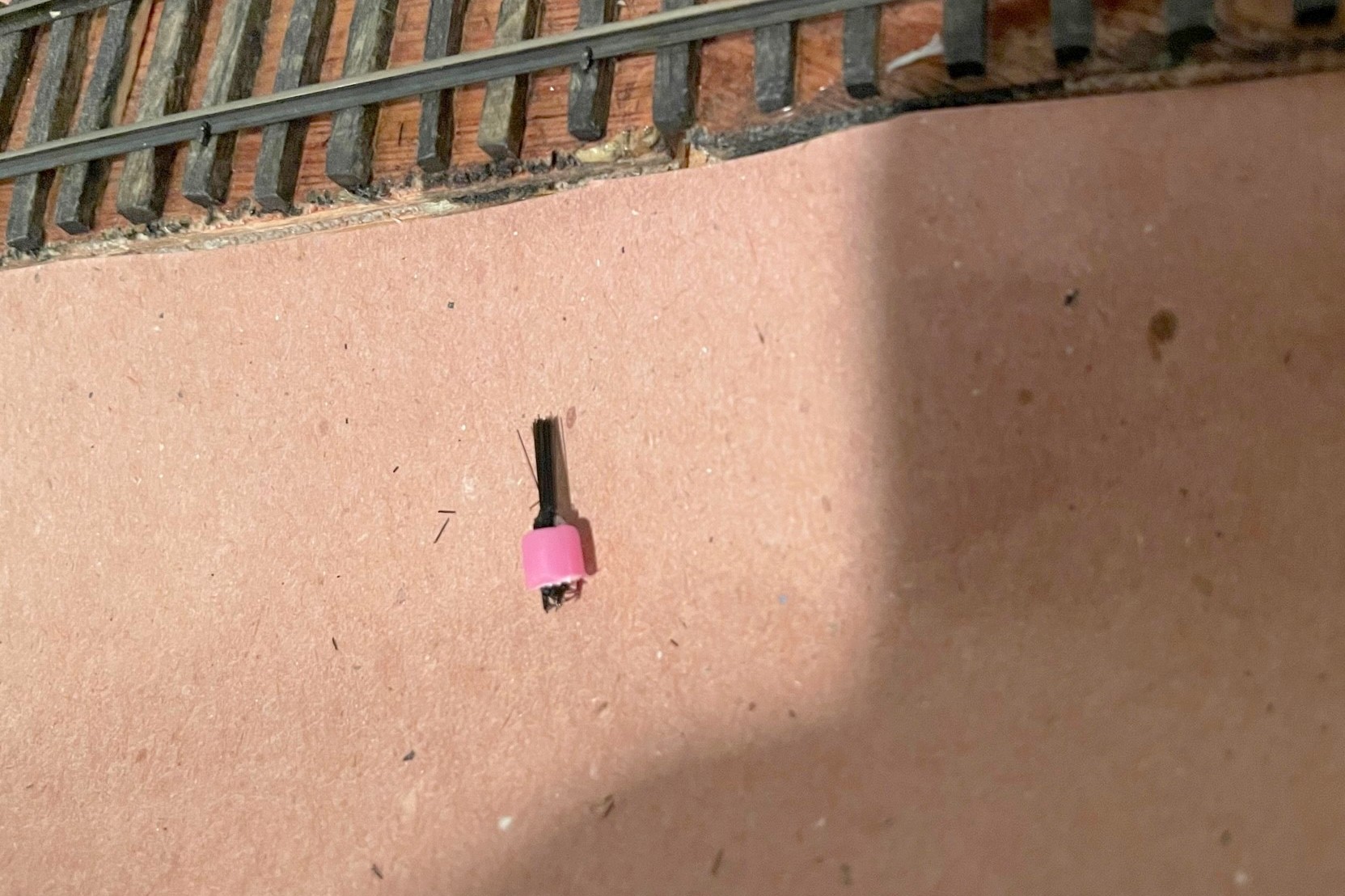
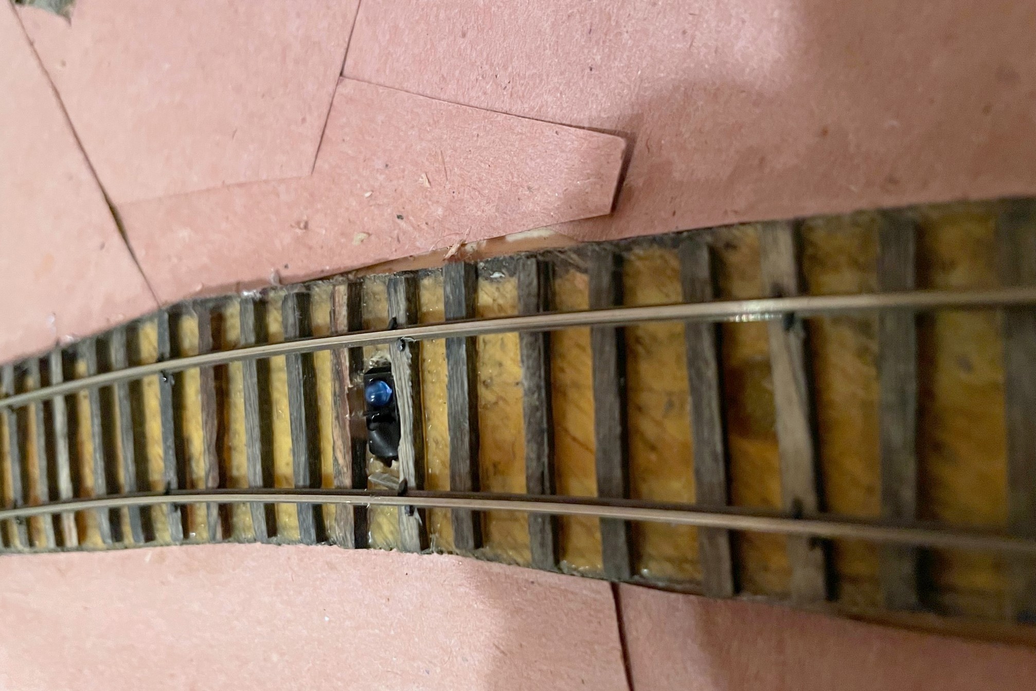
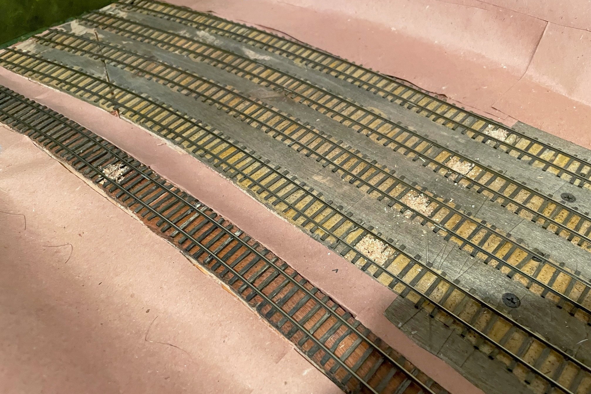
The second step is to drill a hole between the ties for each hand brake location. I found a 5/32″ bit drilled about 1/4″ deep worked for my paintbrushes, and I offset my holes closer to one rail to avoid constantly hitting delicate air hoses on cars. To prep the paintbrush, I first cut off about 3/16″ of the bristles with scissors–the idea is to have them tall enough to catch axles but not the sills of the cars or cut levers. Then I thin out the bristles by repeatedly cutting into the brush with just the tip of the scissors while rotating the brush around. How much you thin it out depends on the grade and how many cars you want to hold, but for my light grades, I trim down to about the last 20 or so bristles. It’s easy enough to thin them a bit more once they’re installed, and if you get it too thin, it’s easy to just make another. Then I use scissors and cut off the brush end of the paintbrush leaving about 3/16″ of the plastic handle to keep the bristles secure. Installing them is usually a press fit, but if they’re loose, a little carpenter’s glue will help hold them in place. I press them down until the handle is below the ties where its bright color will be covered up by ballast.

Paint brush handbrake installed
Paint brush handbrakes installed between the rails

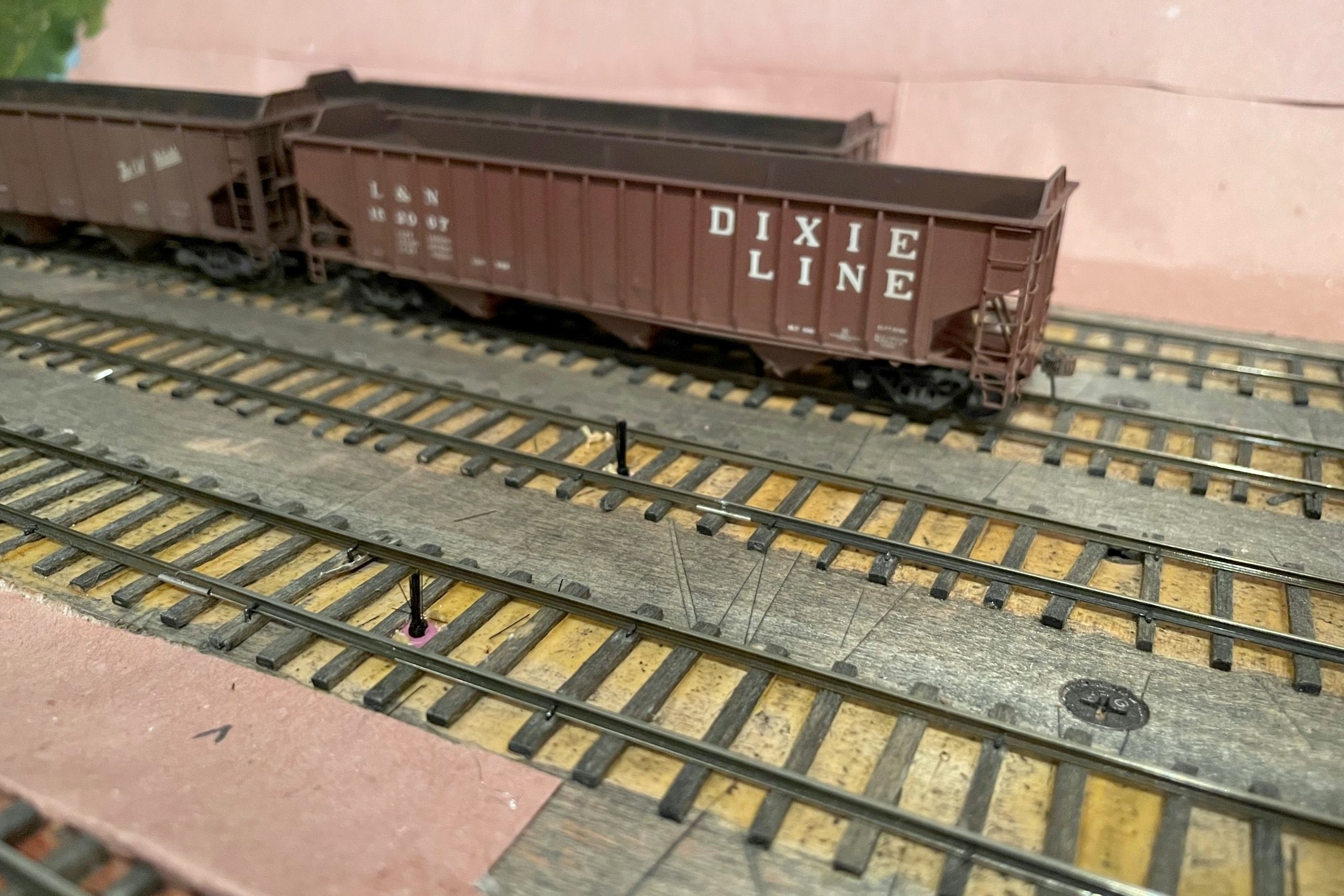
The final step is to test the brake by running strings of cars across them to make sure they don’t derail and don’t cause any noticeable jerking movements in the cars (if you look closely, you’ll see some movement, you just want to avoid it being distracting). When you let go, the cars should roll and then come to a gentle stop once they hit the brake. Also test a locomotive across each brake to make sure it doesn’t interfere with the trucks (this is the most stressing pressure on the brake). On steeper grades, you may find having a few brakes in series is needed to stop a string of rolling cars, or you may have to spot the cars exactly on the brake to prevent them from rolling in the first place. It’s easy enough to add and remove these brakes while you’re trying to figure things out. In the end, I’ve found this is a great way to hold cars in place without the worry of damaging cars or scenery, and it’s tough to beat the price and ease of installation!

Paint brush handbrake in front of tipple
Finished “handbrakes” to hold the loaded cars in front of the Mayflower tipple mock-up

Installing Automatic Grade Crossing Signals

CV Local and grade crossing signals
The CV Local led by L&N RS3 100 crosses Bonny Blue Road with its newly installed crossing flashers

Many of the grade crossings on the St Charles Branch didn’t have flashing signals and were protected by flagmen or fusees (see how I simulate fusees here), but a few of the more prominent crossings were protected by automatic flashing signals and bells. One of those crossings is Bonny Blue Road which crossed two legs of the wye in St Charles. I was looking for a way to make these signals work automatically with nothing required of the crews (beyond sounding the horn for the crossing) and no hardware needed on any rolling stock. I quickly settled on using IR sensors mounted near the tracks to trigger the circuits required for the crossing. While many of the major manufacturers of railroad electronics offer circuits for flashers and for triggering based on sensors, there seemed to be a lack of good, simple options for the sensors. So I did what many of us do when we’re looking for something–I turned to eBay.

I found a lot of products for flashing crossing signals, but one it particular caught my eye. A company called “WeHonest” was offering what looked to be decent looking LED signals that came with a flashing circuit for a very reasonable price. Being a little suspect of a foreign company calling itself “WeHonest,” I needed four signals, so I ordered a couple sets and hoped for the best. I ordered the signals with two heads instead of four (front and back) because my signals would only been seen from one direction, and the ones with four heads looked too thick front-to-back (I plan to add dummy heads on the back later). When they arrived a couple weeks later, I was impressed with the quality for the price. The lettering is easily readable, the construction is mostly metal, and the size and shape are good for HO scale. I had to clean up some areas of the metal crossbucks, and some of the silver paint flaked off, but these were easy fixes. I initially hooked up the flashing circuit to a pushbutton on the fascia, and the flashing circuit worked flawlessly and controlled all four signals in a synchronized manner.

The signal piece was solved, so now I needed a way to automatically control them. My confidence in “WeHonest” was bolstered, so I explored their options. They offer a “model train detector automatic signal controller crossing system trigger etc” (also called a “master board”) which shows a diagram of how it can be configured to trigger a grade crossing flashing circuit using simple, single-unit IR sensors that don’t require a broken path. I also needed a circuit that could support four sensors due to the tracks that would trigger this grade crossing, and while the board only supports two sensors, their diagrams show that you can connect more sensors via separately available splitter cables. They also offer a sound effect circuit with multiple grade crossing signal bells (and a rooster). I ordered a master board, sound effect board, two splitters, and some additional IR sensors.

Wiring Diagram for Grade Crossing Signal Circuits
Wiring diagram showing the connections needed between the three circuit boards, signals, and sensors

The documentation you see on eBay is all you get, so it took some studying and tinkering to set things up, but it wasn’t difficult. The basic idea is the master board is connected to 12V DC and the IR sensors. The sound effect board and flasher circuit are daisy chained off the 12V DC “output” side of the master board which is only live when the IR sensors are triggered. The only surprise on wiring was there are no normal contact screws for the 12V DC input, only a plug for an adapter and a specific connector type (both of which are sold separately). I found a plug off an old RC helicopter I disassembled years ago that did the trick. I mounted all three circuits and the speaker on a piece of masonite to keep the wiring tight and organized. Rather than use the supplied speaker, I attached a pair of baffled cube speakers I had pulled out of a locomotive when I replaced it with a Scale Sound System speaker.

Grade crossing circuit boards
I mounted all three circuits and the speaker on a single piece of masonite to declutter and protect the wires

I installed the IR sensors between the rails and ties as the company indicates in the pictures. When anything passes over it within a couple inches, the IR sensor is triggered. There is no documentation on how the sensor works, but it has two elements, a blue dome and a black dome. I can only speculate that it transmits IR from one dome and receives reflected IR in the other dome. When I hooked everything up, it worked great… with two IR sensors plugged into the two separate sensor inputs on the master board. When I tried to use all four IR sensors, it would trigger the circuit no matter what I did even if nothing was present. I noticed some sensors were more sensitive than others, so I experimented with different placements and combos and even the positioning of the elements within the sensor. Unfortunately, I destroyed one of my sensors in the process, but thankfully they’re inexpensive, and I found the WeHonest customer service to be very responsive and helpful!

Grade crossing IR sensor
Here’s an IR sensor with a portion of the black dome covered in electrical tape to decrease its sensitivity

When my replacement sensors arrived, they did the exact same thing as before. Two sensors worked fine, four sensors triggered the circuit even with nothing present. I really liked the overall operation of these circuits, so I kept experimenting to see what might work. I speculated that the circuit detects based on a threshold of received IR energy–with one sensor, the ambient IR was low enough to stay below the threshold, but with two sensors, the ambient IR increased above the threshold to make it appear a train was present. I found that if I covered a portion of the black domed element on some of the IR sensors, it would keep the circuit from triggering but would still trigger if a train passed. After playing around, I found covering about 60% of the black element of all IR sensors with a small piece of electrical tape made everything work as intended.

Now that I’ve worked out the kinks, I’m very happy with the crossing! I’m able to control the sensor sensitivity via the electrical tape, I can control the flash rate of the LEDs via a dial on the flasher circuit, I can select the bell sound from one of several good options on the sound effect circuit, and all of this works automatically with no actions needed from the crew. I have two more flashing grade crossings to go on the upper level, and I’m satisfied enough that I’ve already ordered the parts to replicate this installation on those crossings.