The last couple of weeks I’ve been working on the fascia and wiring for the staging level, and I’ve also installed the DCC system. It’s a lot easier to install when there isn’t a lot of layout in the way, and most of it resides on the bottom deck anyway.
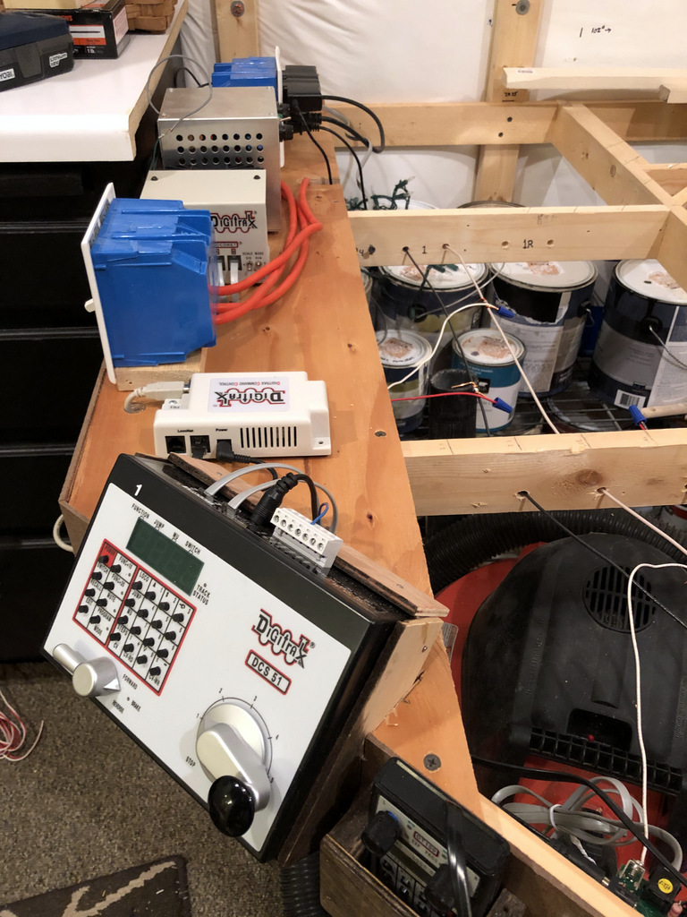
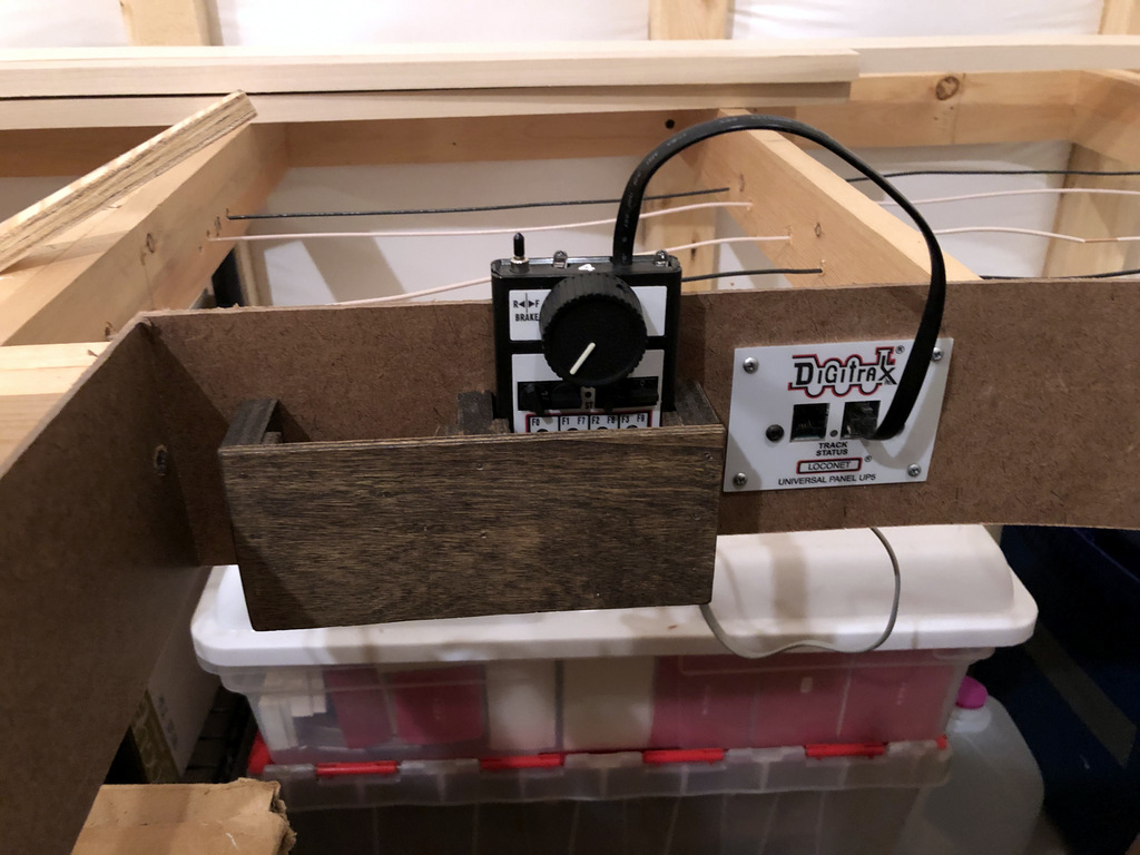
I’m using the Digitrax DCC components from my last layout. While I have an upper-end DCS100 “Chief” system, I’m actually using a smaller, entry level DCS51 Zephyr Xtra as my command station. While the Zephyr doesn’t have the same functionality as the Chief, it’s got everything I need, and it’s much simpler to operate. Like my previous layout, I’ve mounted it on the fascia where it’s easy to access and can be used as a throttle for the staging tracks or for smaller visitors.
The rest of the throttles are UT4D 2-way wireless throttles connected through a UR92 wireless receiver/transmitter. Even though everything’s wireless, I still use several UP5 throttle plug-ins around the layout. This allows someone else to bring and use their favorite Digitrax throttle, and it allows an ops session to go on if the wireless is acting up. Each of the panels has an adjacent throttle pocket that perfectly fits the UT4D throttles (those who visited my last layout will recognize these). This not only gives the operators a convenient place to set the throttles, but it protects the buttons and also promotes the plugging in of throttles when not in use to preserve batteries.
I’m using three sources to power components. The first is straight wall power, and this powers the UP5 panels to supply keep-alive power to the throttles (preserves batteries while the layout is off). The second is switched power for the DCS100 and UR92, and the third is switched power for the Zephyr command station and a PR3 computer interface. I kept these separate so I could turn on just the “Z” and PR3 when I’m programming locomotives.
One lesson I learned from my last layout was to keep a functional diagram of the Digitrax setup so I could easily determine how the components are wired together even when they’re covered by the layout–it’s a great aid in troubleshooting!