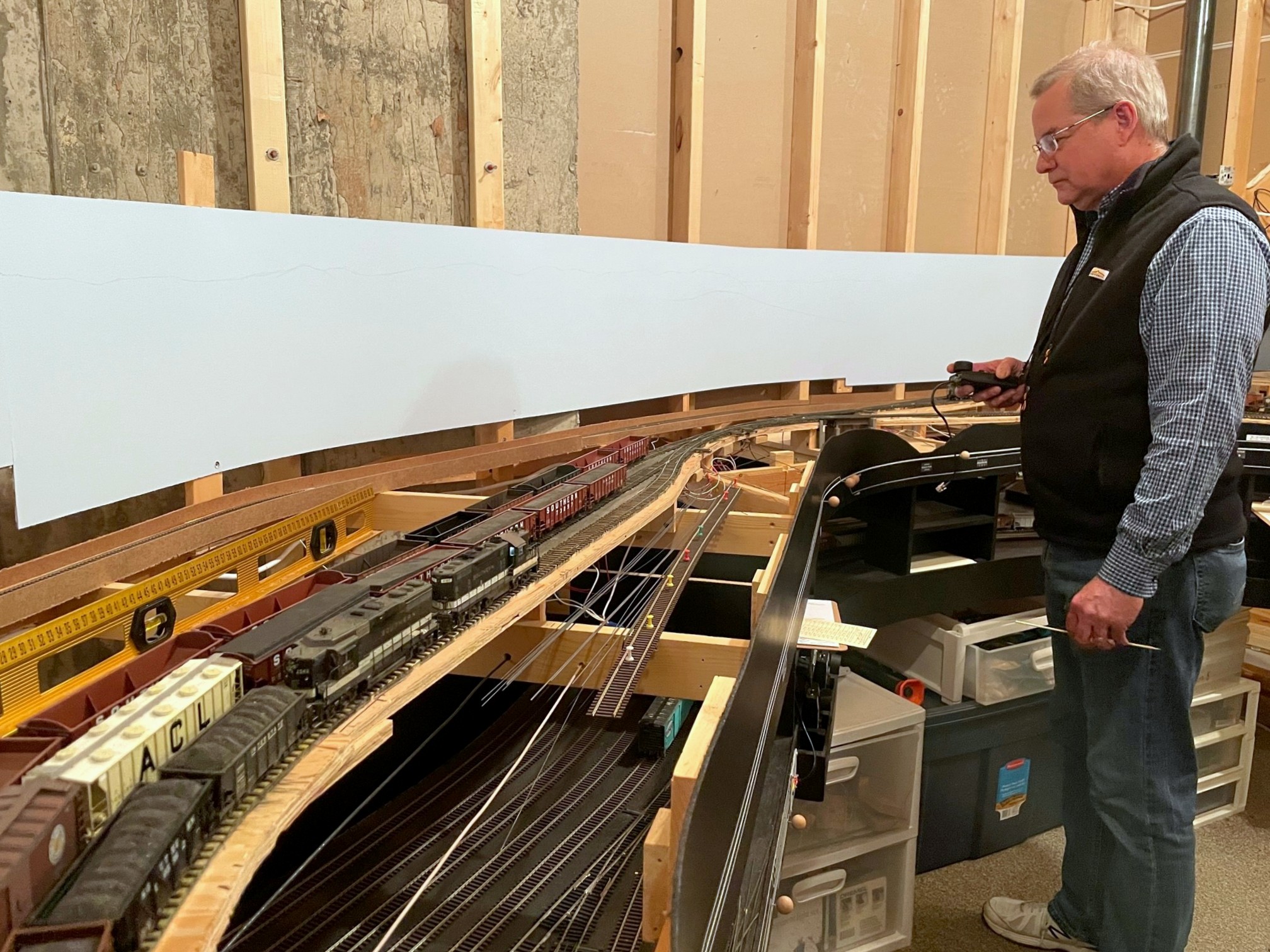
Patrick working the St Charles Local–dropping off fresh empties and picking up loads to take back to Appalachia and Andover
Yesterday was the second operating session on the St Charles Branch, and Patrick Tillery was again my partner in crime. Despite only having the tracks for one deck complete, we were able to run 4 trains, and it took us about 2 1/2 hours to get all the chores done. That’s a pretty good showing for only 1/2 the layout and 2 operators! I learned a lot in the session, mainly which switches to keep working on to avoid derailments, but at least we didn’t have any repeat offenders, so I’ll call it progress!
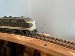
L&N 100 (still an “in progress” model) works Mayflower as the power for the CV Local
For this session, I picked the date July 30th, 1969 which meant F-units for the Southern’s mine run and and RS3 for the L&N. We ran a “busy day” with two Southern mine runs. Since the helix was recently completed, I staged the “Black Mountain Local” on the helix with loaded hoppers as if it was returning from the tipples which will eventually be on the upper deck, so it was more like 1/2 a train, but it did add a little more operation as the train needed to be blocked in the yard and the power tied up. It also required some “meets” in St Charles, so the orders needed to specify which legs of the wye to occupy and which to leave open for the higher priority trains. No collisions, so I guess I’ll call that a success.
In addition to having a full set of fascia controls to work with and the beginnings of backdrops, this session had some other notable “firsts”
First session with first gen diesel sounds (EMD 567s and and Alco 244)
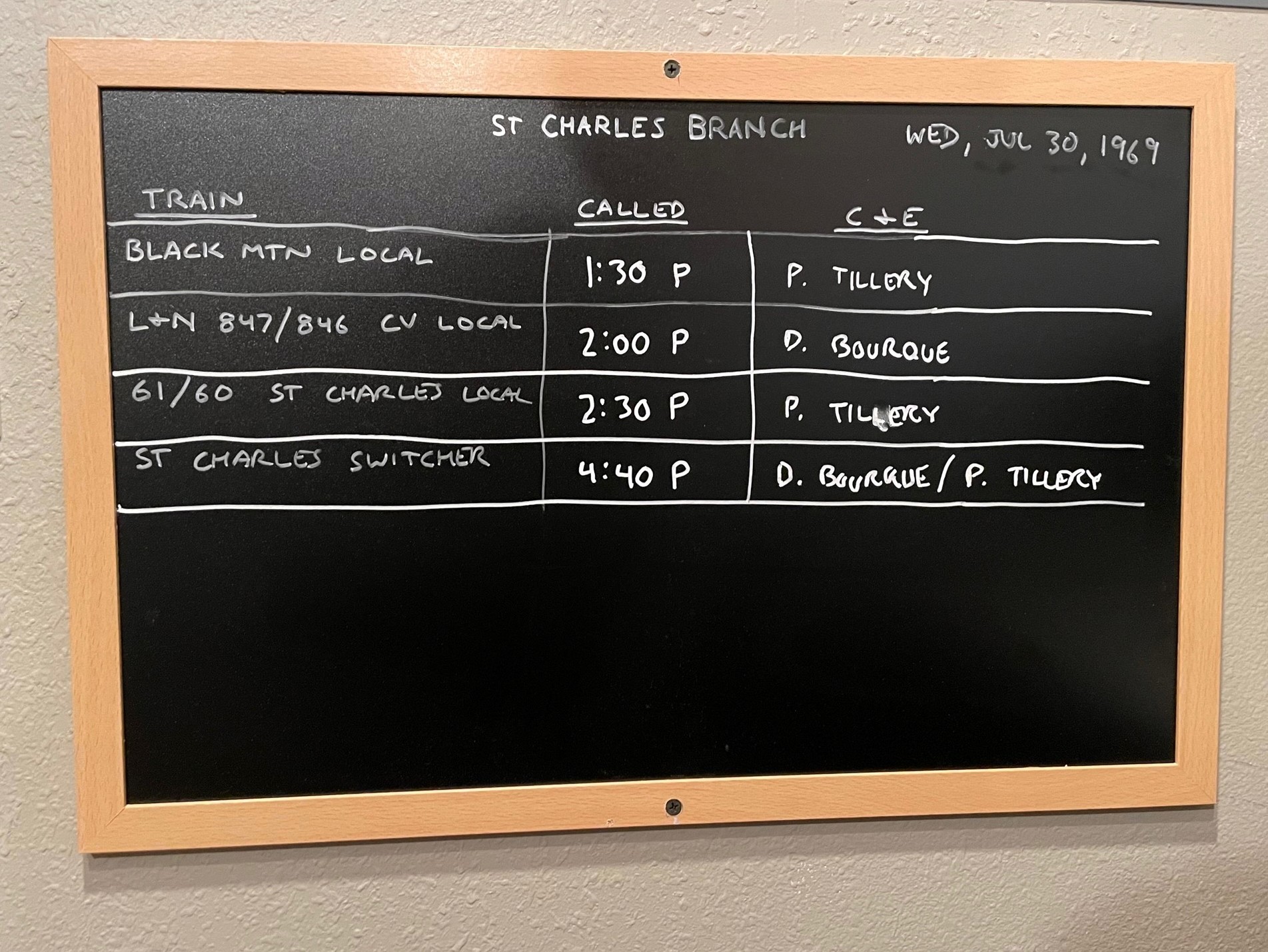
This is the makeshift job board for session #2 and the 4 trains we ran
Some things I learned:
Even with the switch lists, I probably still need a “master switch list” everyone can access
Instructions for the crews need to be a little more explicit on the job required and not just a blocking sheet
A little momentum in the locomotives made it more fun and realistic–I’ll probably turn it up a bit more next time
Even though it’s a small chore, using the switch locks and semaphore controls added some prototypical realism and slowed things down a little (which is good)
Overall I’d call it a success. It was fun, and it motivates me to keep going! If anyone reading this is ever in Colorado Springs, give me a shout and we’ll set up another.
This is the makeshift job board for session #2 and the 4 trains we ran
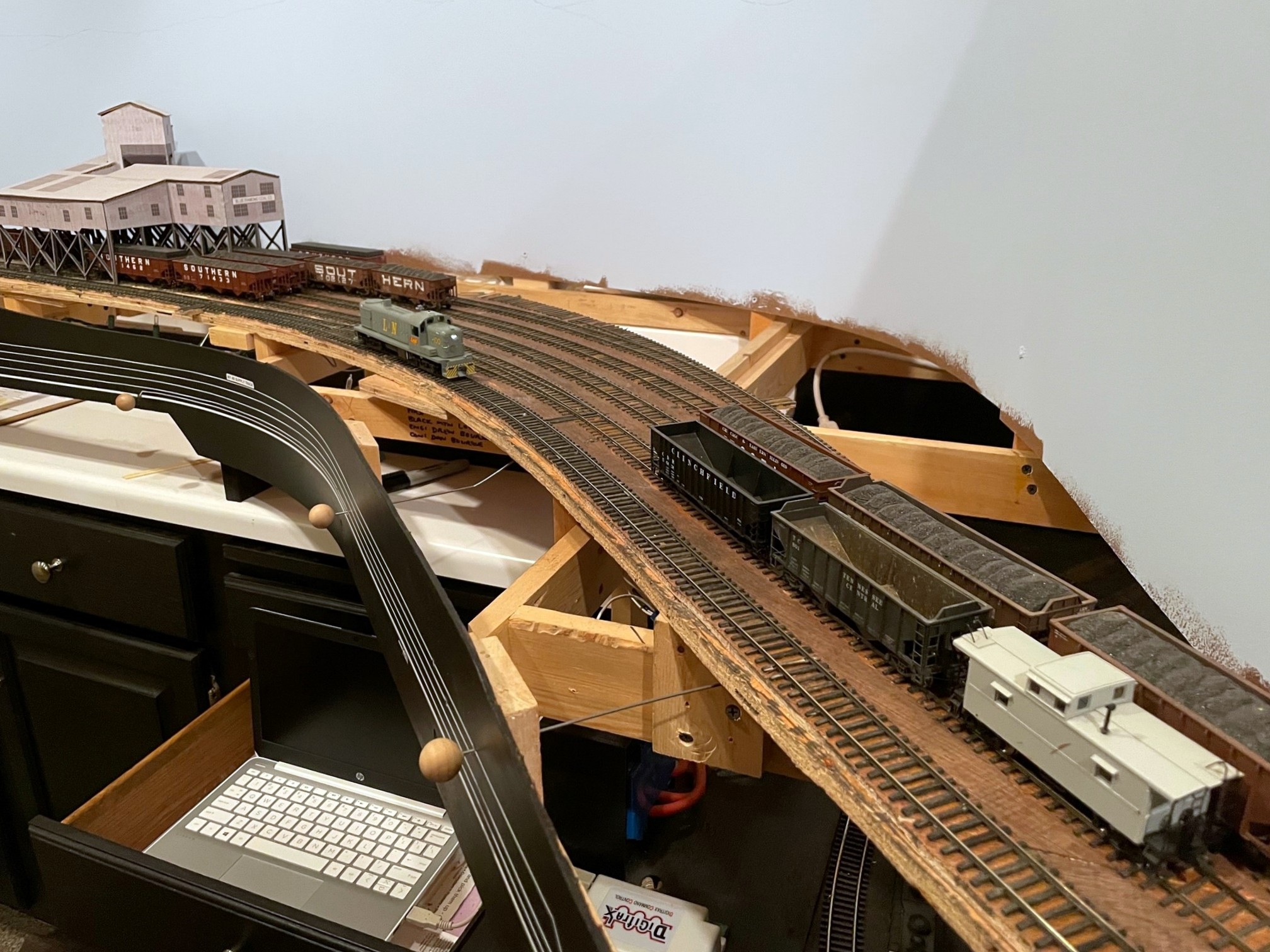
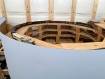
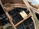
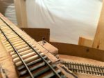
Since there’s no upper deck yet, the helix served as a staging track for the “Black Mountain Local”
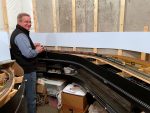
Patrick finishing up the Black Mountain Local by blocking cars for pick-up by the St Charles Local
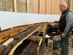
L&N 100 (still an “in progress” model) works Mayflower as the power for the CV Local
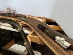
Patrick working the St Charles Local–dropping off fresh empties and picking up loads to take back to Appalachia and Andover
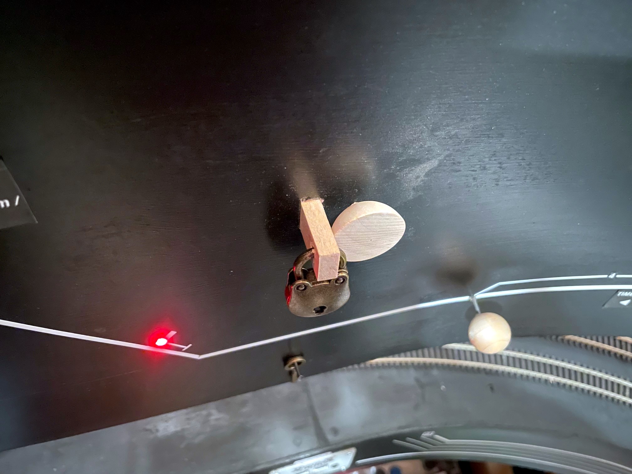
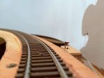
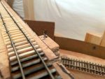
The Black Mountain Local stops to reset the dwarf semaphore now that their work is complete
Semaphores were a common way of signaling trains on the Southern Railway. Semaphores were often used at stations to indicate whether or not the train was cleared to proceed or needed to stop (or at least slow down) to pick up orders. Semaphores were also used to protect branches when trains were working on them, and these semaphores were usually set by the crews themselves. The St Charles Branch employed three such semaphores to protect the lines RR west of St Charles. Here’s the exact verbiage from the Employee Timetable:
“At points shown below, semaphore signals will govern the movement of trains and engines. When track is not occupied, signal will indicate proceed. When in either position, stop or proceed, signal will be fastened and locked with a switch lock. When indicating stop, position will not be changed until train or engine occupying the track clears it and the crew of same restores signal to proceed indication. West of St. Charles—located at the junction between Bailey Trace and Fawns Branch lines.”
I definitely wanted to model this aspect of operations, and as a bonus, two of the locations of these semaphores correspond with long sections of hidden track on my layout, the hidden track between St Charles and Mayflower on the Bailey’s Trace Branch, and the helix between St Charles and Turner’s Siding on the Black Mountain Main. These would not only serve the purpose of adding more prototypical operations, but they would also serve a very practical function of protecting trains that can’t be seen without a dispatcher.
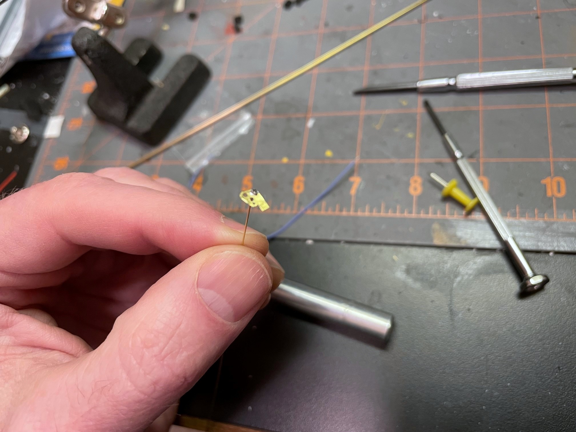
I learned from a former Southern employee who worked in this area that these were “dwarf semaphores.” I haven’t been able to find a picture of one of these exact devices near St Charles, so I Googled “dwarf semaphore” to see what they were all about. They operate just like the tall semaphores and come in both upper- and lower-quadrant designs, and most have lights. They only sit about 3-4 feet tall, though, and have a blade somewhere around 14″ long–that’s super tiny in HO scale! I picked a Union Switch and Signal upper-quadrant, two-light design. I didn’t see anything resembling this available in HO scale, so I set about building my own operating version from sheet brass and wire.
Faceplate and blade made from brass with the swivel wire soldered in place
I made a drawing of the blade and faceplate with the lights, sized it down to HO scale, and printed it on sticker paper. After sticking it to a sheet of .005″ brass, I was able to drill holes for the lights, swivel and actuating arm and then cut it out with scissors. After cleaning it up with a file, I bent a piece of .015″ brass wire, inserted it through the swivel hole, and soldered it to the faceplate. I drilled a hole for the wire through a piece of 1/16″ brass tubing for the base. I wanted to use fiber optics for the lights, so I soldered a 1/16″ long piece of tube to the tall tube angling up to where the light would be to hold the fiber optic strand. I painted the faceplate and tubing black, then made lenses by melting the end of a piece of fiber optic into a mushroom shape holding it near a soldering iron. A little red for the blade and a white sticker stripe and the faceplate was complete.
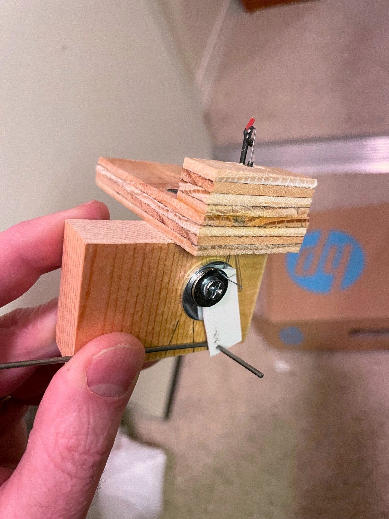
Completed dwarf semaphore model and lever mechanism
I mounted the base post in a piece of plywood and drilled a hole for a second piece of 1/16″ brass tube underneath the blade for the actuator arm. After inserting the faceplate and securing it with a bend on the back side of the tube, I had a faceplate that swiveled freely. A piece of .012″ steel music wire bent at a 90 degree angle at the end was inserted into the blade and the tube for the actuating arm. On the bottom, I made a lever for the actuator that raised the actuator just slightly while allowing for significant travel for the longer actuating rod connected to the fascia. I filed the end of a fiber optic strand so it would be parallel to the faceplate and inserted it into the little brass holder and through a hole in the base. A little silver paint for the post, and the tiny dwarf semaphore was complete!
One of the things I wanted to model was the use of switch locks. I found some Miniature Locks on Amazon that suit this purpose perfectly! I decided to use a slide-switch mechanism like I use for all my switch controls, but I needed a longer slide to enable the lock to go in front of and behind the control knob to “lock” it into either position. I found some old three-position slide switches on eBay that did the trick! The slide switch serves two purposes–it “snaps” into position to hold the control and semaphore securely in position, and it allows for the routing of power to LEDs, in this case some bi-color red and green LEDs that change color when the polarity is reversed, something easy to do with a slide switch. After mounting the switch to the layout using a piece of 1×4″ board, I drilled two holes in the slide handle and used .o62″ steel wire to connect the slide to the lever under the semaphore and a separate rod through the fascia for the control knob, a 1/2 ball piece of wood.
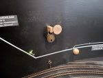
Semaphore control in the “stop” position showing the red fascia indicator and lock
For the lock mechanism, I used a bar of 1/4″ x 1/2″ basswood with a hole drilled for the lock and inserted it through a hole in the fascia and benchwork adjacent to and just touching the control knob. The hole sits just ahead of the control knob when it’s pressed in and just behind it when pulled out. I also connected two LEDs to the slide switch and a 12V DC power supply. One LED is mounted behind and just through the fascia to serve as an easy indicator for the full-size operators. The second was inserted into a hole drilled in the semaphore base where it can shine into the fiber optic strand.
The result is a semaphore with working lights, blade and a switch lock. While the dwarf semaphore sits about 3′ from the aisle and is tough to see, it is pretty cool to have an operating model and a tiny little red or green glow that matches the indicator on the fascia. Now the operators on the St Charles Branch, just like their real-world counterparts, have to stop at the semaphore, unlock the lever, change the indication, and re-lock the lever before proceeding up the branch (and do the reverse on the way back). While I’m not sadistic enough to make operators lock and unlock every switch they need to throw, working with switch locks a couple times during a session is one more step toward replicating the actions required on the real thing, and it adds a little prototypical time to the work required. Oh, and it helps protect trains without a dispatcher which is pretty useful.
[Note: since I first published this post, I decided to reverse my control mechanism so “proceed” is pulled out and “stop” is pushed in. It just required me to reverse the lever used to lift the arm. I figured having the crew move the lock to the front of the pull knob where it’s more obvious makes more sense.]
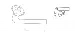
My PowerPoint drawings of semaphore blades and their HO scale counterparts
Faceplate and blade made from brass with the swivel wire soldered in place
Close-up of the mostly complete dwarf semaphore made from brass and fiber optics
Completed dwarf semaphore model and lever mechanism
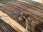
The three-way slide switch wired up–the short leads are for the LEDs, the long leads connect to 12V DC
The internal guts of the control mechanism showing the two control rods routed through the handle of a slide switch
Two holes in the fascia, one for the control rod and one for the locking bar
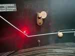
Finished dwarf semaphore in the “stop” position–note the red light
The Black Mountain Local stops to reset the dwarf semaphore now that their work is complete
HO scale dwarf semaphore in the “stop” position
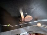
HO scale dwarf semaphore in the “proceed” position
Semaphore control in the “proceed” position showing the green fascia indicator and lock
Semaphore control in the “proceed” position showing the green fascia indicator and lock
Semaphore control in the “stop” position showing the red fascia indicator and lock
Semaphore control in the “stop” position showing the red fascia indicator and lock
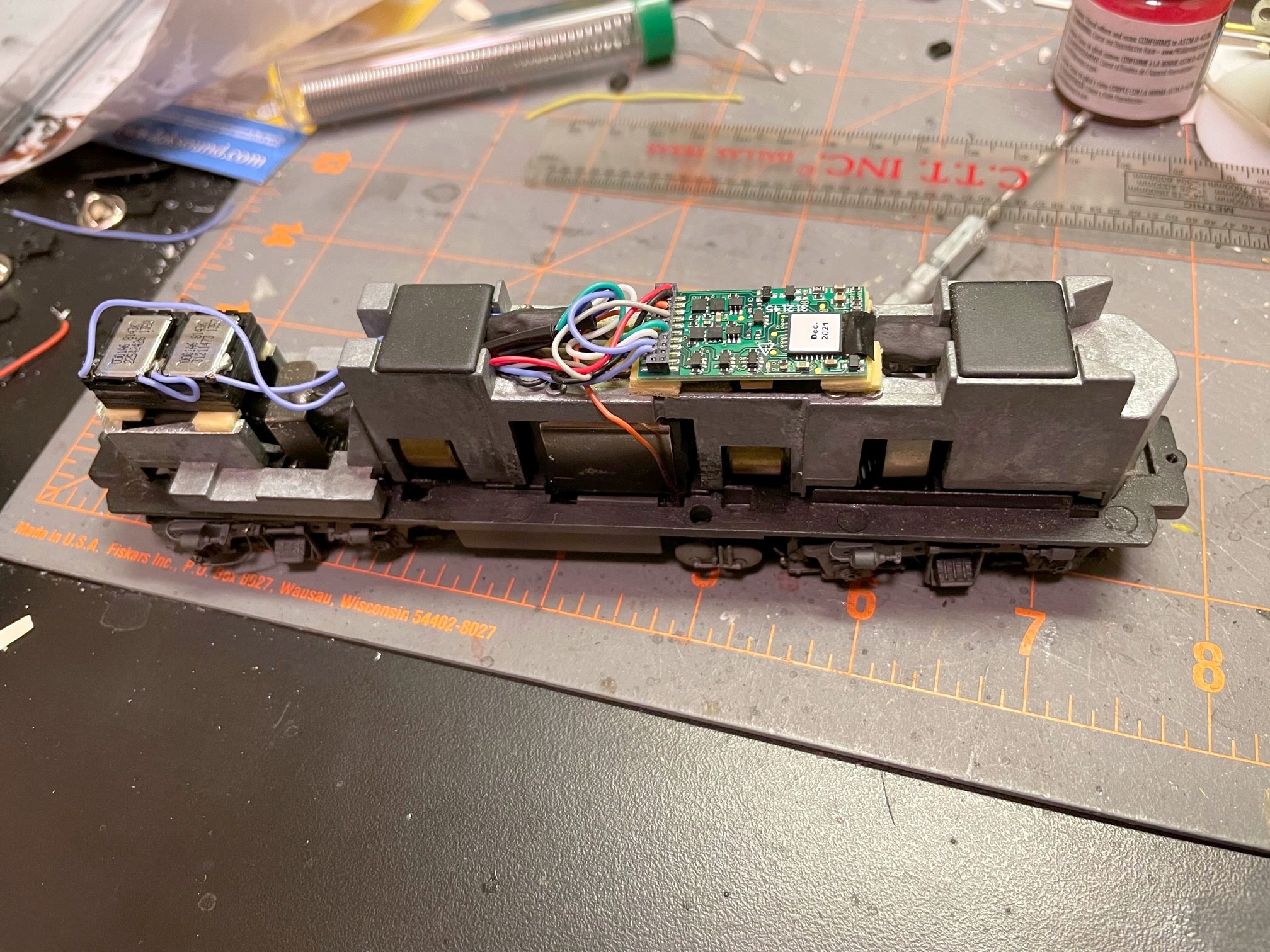
You may remember Southern GP7 2187, a Proto GP7 I finished last summer. Well in addition to fixing the railings and steps for my 1970 timeframe (black and white instead of yellow), I decided to install sound. Now sound is something pretty new and intimidating to me, but after running a couple factory-equipped sound locomotives, it was tough to go back to no sound. I finally decided to just jump in! There are many great sound decoders out there, and everyone has their preference. I won’t claim to be an expert, but after doing some research, I decided to start with some Soundtraxx Econami decoders. As you might guess from the name, these are “budget” decoders that run about 2/3 the cost of a full-featured sound decoder from any manufacturer. The Econami is pretty basic, but it does have the key features I need, and it uses the same basic sounds as the more expensive Tsunami 2s. Best of all, the Econami Diesel version allows the user to select from a handful of prime movers including everything I need for my first-generation fleet: the Alco 244 for RS3s and the non-turbo EMD 567 for Fs, GP7s and GP9s.
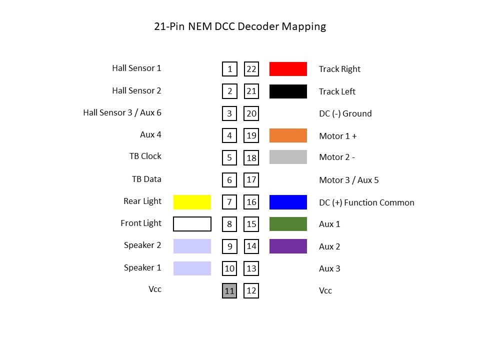
Basic mapping of a 21-pin connector for DCC (use at your own risk)
Soundtraxx makes two versions of the diesel Econami, the larger ECO-PNP and the smaller 21-pin ECO-21PNEM. I picked up a couple ECO-PNPs, one of which was intended for 2187, but once I got the decoder, it was obvious that it wouldn’t fit without major modification to the large metal weight–I needed something smaller. After installing the PNPs in an RS3 (just barely) and an F3A, I decided I was happy with the sound produced by the Econami and a pair of mini cube speakers, so I looked to see if I could install the smaller 21-pin decoder in the GP7. The 21-pin arrangement is newer, and I was surprised at how tough it was to find a cheap 21 pin harness I could wire into the locomotive. You can find cheaper ones in Britain, but it was going to cost me an extra $20 to get one in the states–what’s the point of using the Econami if a simple harness was going to eat up all the savings?
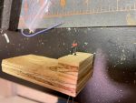
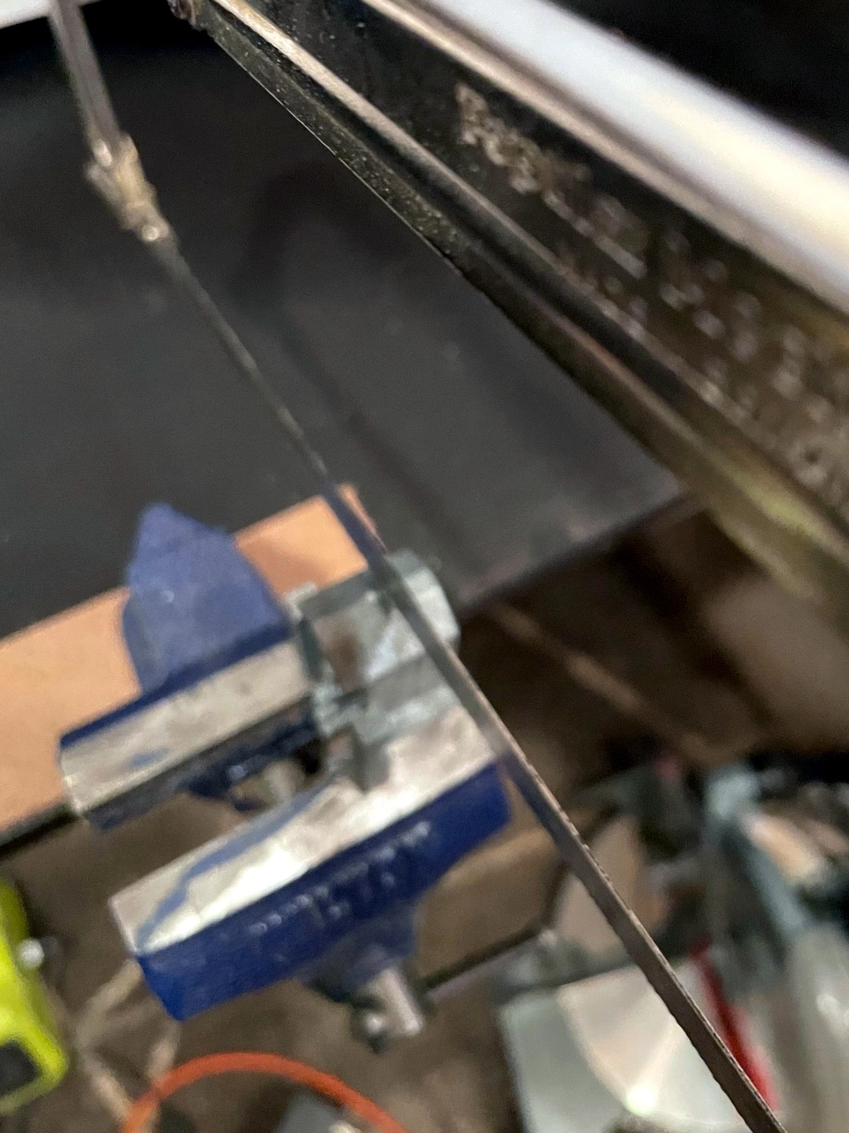
Taking 8mm off the height of the weight in the nose of the Proto GP7 to make room for speakers
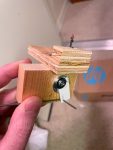
So, could I get the 21-pin Econami to work without a harness? While it was a little tough to find info, I finally figured out the mapping of the 21 pins (thankfully German shares some commonality with English…). I knew it wouldn’t be practical to solder directly into the decoder (the pin holes are tiny and close together), but I thought I might be able to shape the wires to act as pins, so I ordered up an ECO-21PNEM. What I found was I could tin the wires on the locomotive, cut the end so about 2mm of metal was exposed, and then carefully insert the wire into the correct pin hole. While the connection is not bulletproof, it’s snug enough that the wires don’t come out easily, and if you can push the wire in until the insulation is flush with the board, there’s little chance of a short. For the extra wires (e.g., speaker wires), I used 30 AWG stranded wire tinned with solder–I had to use a little extra solder to get a snug fit, so a 28 AWG wire would probably work as well. Once I verified everything worked, I used a piece of electrical tape to hold the wires down and in-place.
Using a 21-pin Econami decoder without a 21-pin harness
Now for the speaker. Unfortunately, I decided to use the large clear plastic blocks for the number boards and lights, so the little room that was left in the top of the shell was taken up. I decided the best course of action was to take the weight off and remove about 8mm of metal height from the nose section with a hacksaw. After filing the cut clean, I was ready to install the speakers. I’m using the 11 x 15mm cube speakers made by Loksound. You can find a lot of sources for speakers this size, but I love that the Loksound versions come with different baffle arrangements including both short and tall and a base to install two speakers side-by-side (my preference). I built a double baffle with the short walls using CA and connected the speakers in series (16 ohms impedence). Yes, the decoder is 8 ohms and the speakers are 16 ohms. My research leads me to believe this is not ideal but is acceptable as long as I don’t run the amp at max, which I don’t–if you have a good technical reason why this is not a good idea and will damage things in the long-run, please feel free to post a comment!
So, in the end, I was able to fit a sound decoder and two small speakers into the Proto GP7 with just a small, one-cut modification to the body weight, and I’m really happy with the sound! I’ve got a Soundtraxx Tsunami 2 EMD diesel decoder now as well, so I’ll do a comparison at some point and let you know how I think the Econami compares. For now, I’ll enjoy the chugging sounds of the EMD 567 and hauling coal hoppers interrupted occasionally by the chimes of a Nathan M5! St Charles is now a much louder place.