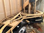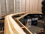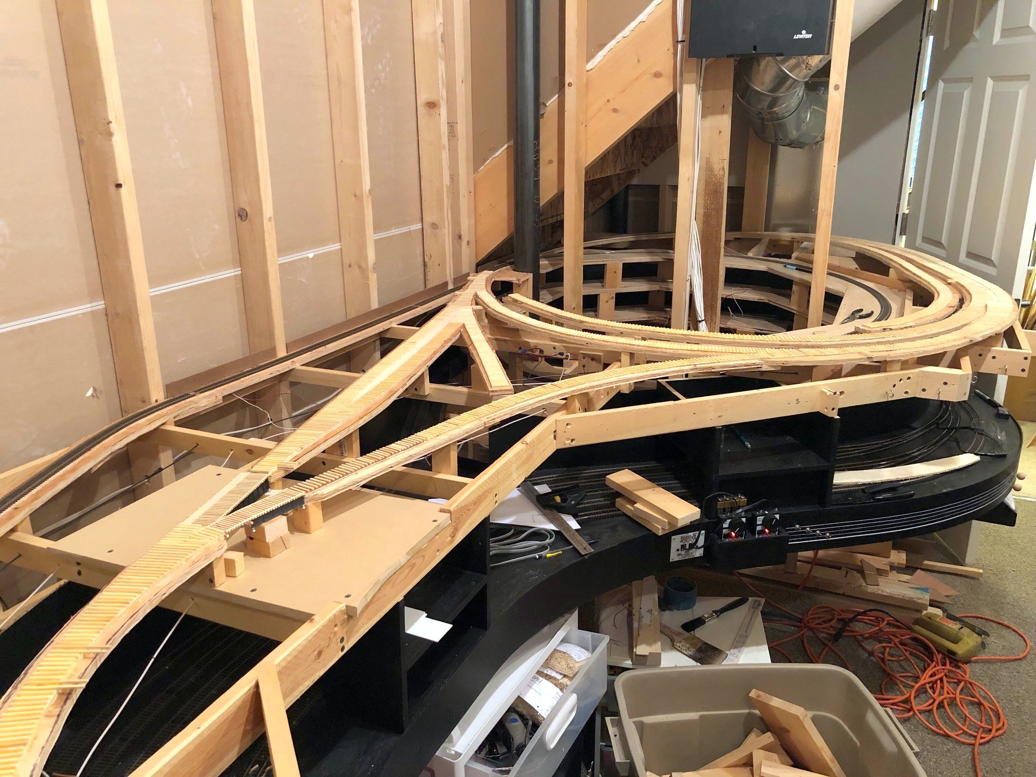
After a nice and productive summer focusing on building models (thank you St. Louis RPM meet for the motivation), I’ve returned to working on the layout. The next step is a big one, the scene of St. Charles, VA. This is the central scene of the entire layout. This is where trains emerge from staging, the site of the local station and engine tracks, the small yard for the branch, and the wye taking trains either up to Mayflower or Kemmergem, Monarch and Benedict. While I could have modeled these tracks in pieces, I decided to do the entire scene at once to avoid further stalling and to limit the need for multiple coats of stain on the ties (takes forever to clear out the smell!).
I’m using basic cookie cutter construction. I lay down 1/4″ door skin ply and draw out the tracks using templates and a piece of flextrack with thumbtacks to hold it in place. After cutting the upper subroadbed, I then trace the pattern only 1/2″ plywood staggering the seams. For this scene, I cut out all the 1/4″ ply to make sure everything fit, then cut the thicker ply. Construction so far is proceeding according to the plan, though I did make a modification to the track plan–instead of having the two small coal-loader tracks butting into one another, I reversed the siding on the wye to place the switch along the benchwork instead of in the back corner where it would be tough to reach. The prototype siding in this area appears to have been double-ended, so it’s not a big deal either way. As a bonus, the new arrangement allowed me to get a few more cars’ capacity on these sidings.
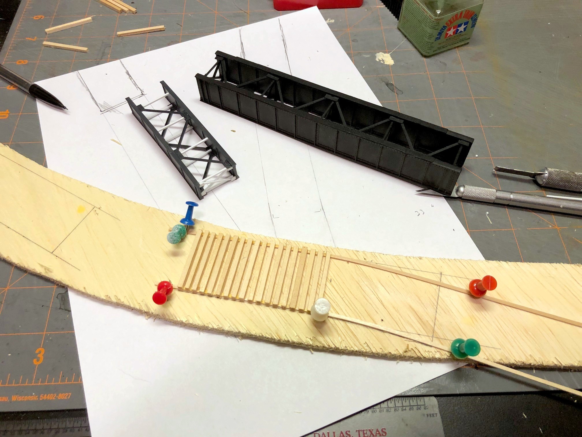
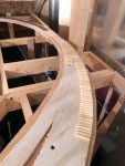
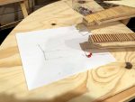
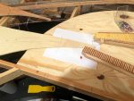
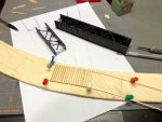
The toughest part of this scene is the pair of bridges across Bailey’s Trace at one end of the wye. On the prototype, there was a plate girder bridge just over 50′ in length on the main, and a shorter plate girder bridge (about 25′) which adjoins a curved bridge portion which appears to have been joined with a short wooden trestle on the curved portion (it’s all been redone with ballasted decks now). I used a 50′ Micro Engineering bridge for one section and cut down a 30′ ME bridge by one section on the other. I hand-laid the bridge ties using a template I drew up on a piece of paper. Next will come the concrete supports so I can attach the bridges and lay the rails across.
It’s encouraging to see progress in the layout room again, and I will definitely have my work cut out for me between now and Christmas hand-laying 14 switches!