This post is less of an update and more of an effort to chronicle a minor but important part of layout construction: DCC track bus planning. Installing DCC has two major components, the first is wiring up the DCC system with its command station, booster(s), throttle panels, computer connections, wireless throttle receiver, and network cables–I covered the installation of the DCC and logical connections of the DCC system here. The second component of DCC is installing the wiring for the track which includes electrical buses, circuit breakers, and dividing the layout into zones which I’ll cover here. Even if you don’t plan to use circuit breakers, its still a great idea to “future proof” your layout by wiring for zones–you can always tie the zones together at the booster, but you don’t want to be installing new buses and feeders under finished scenery. These zones will also help with electrical troubleshooting if you can’t find a short–you’ll at least be able to isolate it to a smaller section of track.
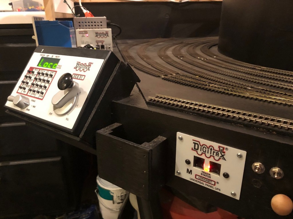
My layout is small enough to easily be powered by a single 5A DCC booster, in my case, an old Digitrax DCS100 Chief acting as a booster (a DCS51 Zephyr is the command station). At most, I’ll have 3 trains and perhaps 6 locomotives running at any given time. The DSC100 can handle this current easily, but with circuit protection provided by only the booster, if any one locomotive runs against a switch and shorts on the frog, power for the entire layout and all trains shuts off. The solution? Dividing the layout into zones and using solid-state circuit breakers!
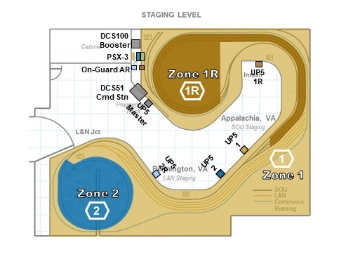
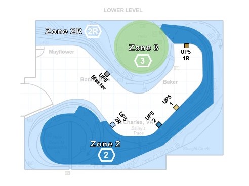
I already needed at least three zones on the layout because I have two reversing loops which need to be isolated from the main bus and powered through an auto-reversing circuit breaker. In my case, I use the On-Guard AR reversing breakers from DCC Specialties. Although a tad on the expensive side, the solid-state AR circuits are rock solid and work more reliably than their analog counterparts, especially with the current draw of sound locomotives. Aside from the reversing zones, I decided to divide the remainder of the layout into 3 additional zones, one per level. How many zones you use is a balance of cost and functionality–too many, and the cost quickly gets out of hand along with the wiring (each zone needs its own wiring bus), too few, and operators causing short circuits will quickly ruin the fun of other operators in the same zone.
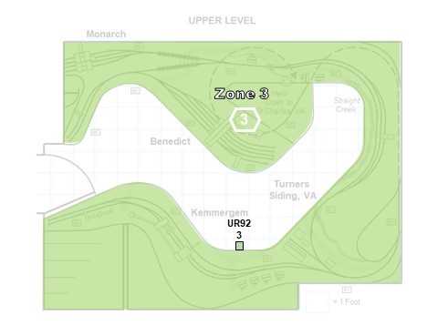
With my max of three trains in mind, I drew zone lines primarily to ensure each train would be in its own zone most of the time. Consequently, the zones are different sizes based not only the amount of track it powers but the operating locations for the trains. For example, zone 3 is the largest on the layout and powers not only the entire upper deck but the helix between the lower and upper decks as well. That’s a lot of track, but only one train at a time will venture to the upper deck, so it can be large. The main level is two zones with one covering the wye and yard at St. Charles, and the second (a reversing zone) covering the branch to Mayflower–there will often be a train at St Charles while another works the Mayflower Branch. Finally, I made the staging level its own zone (along with a second reversing zone) so that operators moving things in and out of staging won’t impact operators on the visible portion of the layout.
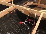
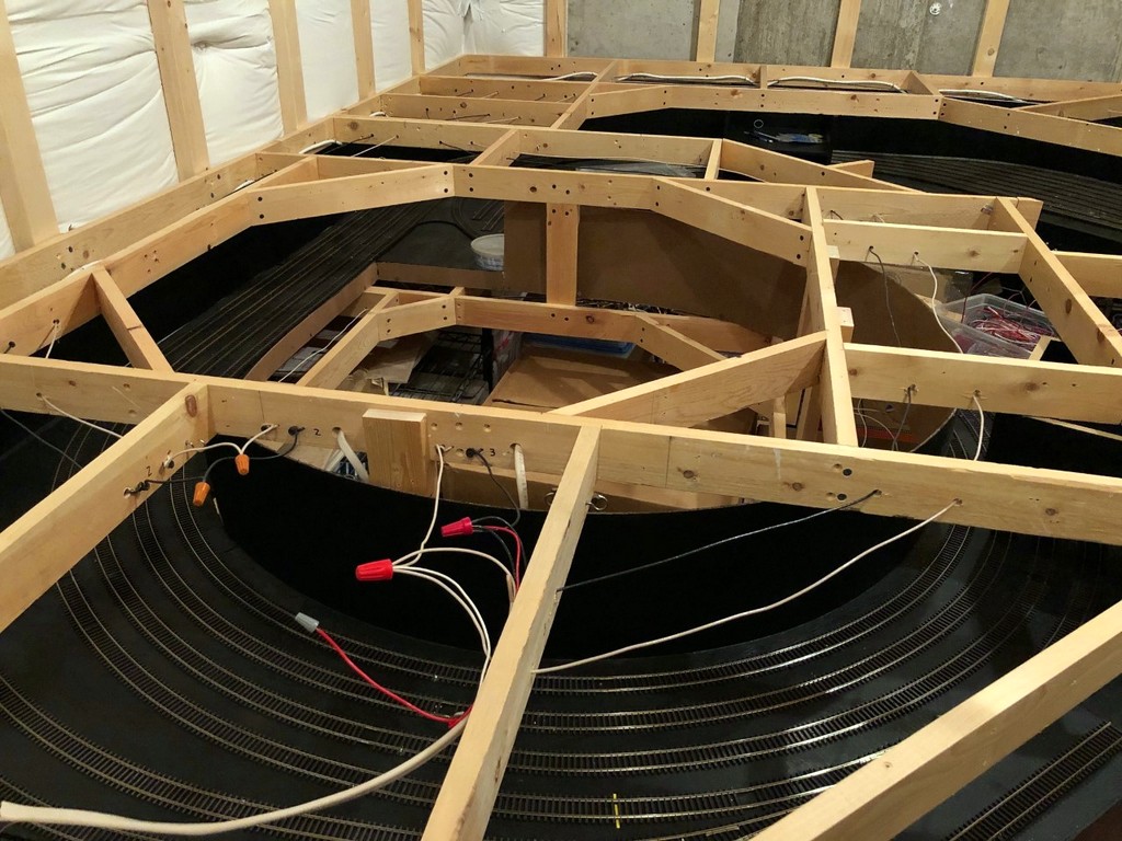
Once I knew where the zones would be, I ran an electrical bus from the vicinity of the booster all along the benchwork where the tracks of that zone would go. I’m all about overkill here, so I use household Romex 14 gauge copper wiring that I pull out of the sheath. I drill holes and run the black and white wires through the benchwork about 4″ apart. One important step is to LABEL THE BENCHWORK with a Sharpie every few pieces of wood, especially if you have multiple buses running side-by-side, so you don’t become confused as to which track you’re hooking up to what zone–if you mess this up, your track could be wired to multiple zones simultaneously and eliminate any benefit of electrically isolating the zones. At the ends of the run, I just wrap the lines around a drywall screw. If I need to run a bus in two directions, I just make a junction and join the three wires together with a wire nut, just like I would do with household wiring.
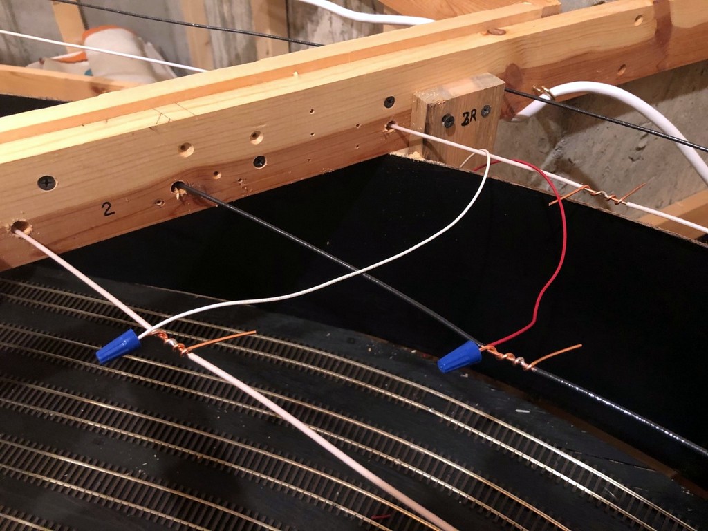
I strip about 1″ of insulation off each wire about every 2-3′ where it will connect to track, and I wrap a 4″ section of the uninsulated ground wire from the Romex around the bare spot about 3 times leaving 1″ or so hanging off both ends. A little solder keeps this pigtail in place. I’ll offset the white- and black-line pigtails by about 4-6″ horizontally in addition to the distance between the wires to minimize the risk of shorts. These pigtails become the connection points for track feeders using wire nuts. Of course, you’ll need to physically separate the tracks between zones by either cutting gaps in the rails or using a plastic insulating joiner. Be sure to overlap your gaps by 3/4″ – 1″ for zones connected to an auto-reverser!
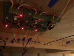
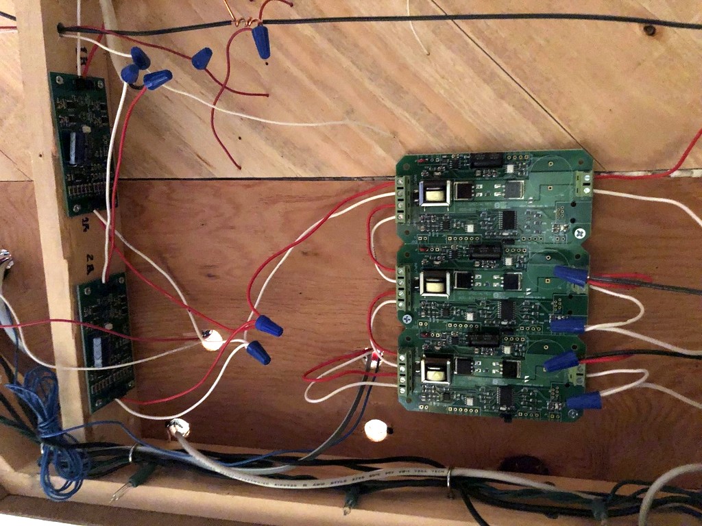
Between the bus for each zone and the booster is a circuit breaker, in my case a PSX-3 (essentially 3 PSX-1s) from DCC Specialties (I covered how to program these with a DCS51 here). Like the auto-reversing breakers, the PSX breakers are solid-state and are well worth the money over analog breakers, especially if you’re running sound locomotives. I have been extremely impressed with these units so far! The PSX design makes it easy to daisy-chain multiple breakers with just one set of wires to the booster. The only split I had to make was after the PSXs when I had to run the last booster connection off the PSX to the two AR circuits. To make the connection to the buses easier, I made a simple “panel” on part of the benchwork where the 14 gauge wires for each bus come through, get wrapped around a drywall screw, and have the ends exposed for connection to the PSX via smaller wires connected with wire nuts.
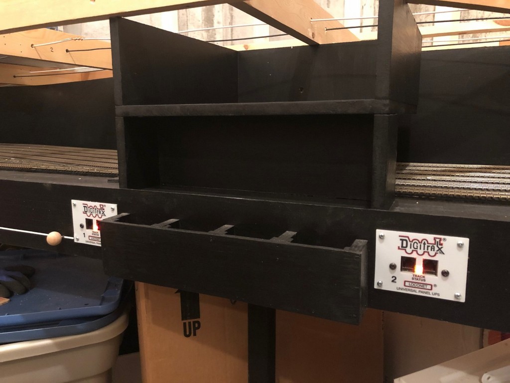
A final step for me was figuring out a way to monitor each zone to know what’s active and what’s shorting out. It’s more difficult to detect a short with the PSX than the DCS100 because the booster makes a distinct noise when it’s reacting to a short, but the PSX is silent. For monitoring, I turned to the Digitrax UP5 universal interconnector panel. I have five of these panels at various spots along the fascia of the staging level for connecting throttles, and each has a “track status” light that can be wired to the track bus. I chose one in proximity to each zone to be the “zone indicator”, labeled with a sticker for the zone number to help me remember, and wired it to pigtails of the corresponding track zone. This way, if a short occurs, only one light corresponding to the affected zone will go out to aid troubleshooting. I wired the UP5 adjacent to the command station and booster directly to the booster wires (no circuit breaker in between) and labeled it to be the master monitor–if it’s on and everything else is out, it tells me the problem is somewhere in the circuit breaker wiring.
Finally, I drew pictures (the ones seen here) of the zones on top of a layout diagram to help me remember exactly where the zones go, and I placed this in my layout binder with all the other helpful information on the layout. This wiring took a good bit of time to plan out and install, but now the layout has the robust electrical backbone to make for smooth connections, easier troubleshooting, and ultimately more fun for operators.