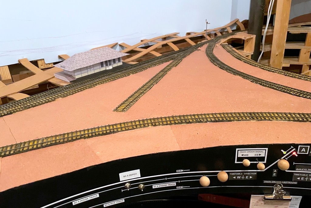
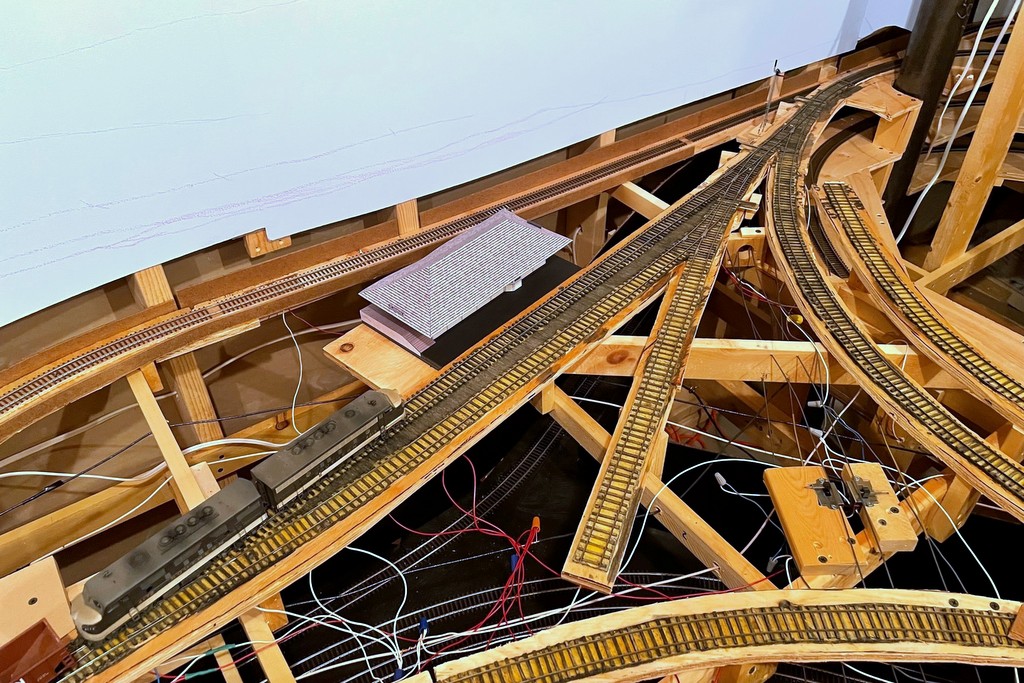
The basic scenery form is now almost done in St Charles–just some cardboard strips and red rosin paper… and lots of glueThe almost finished crossing after whittling, sanding, and scribing lines and bolts with an X-Acto blade and thumbtack
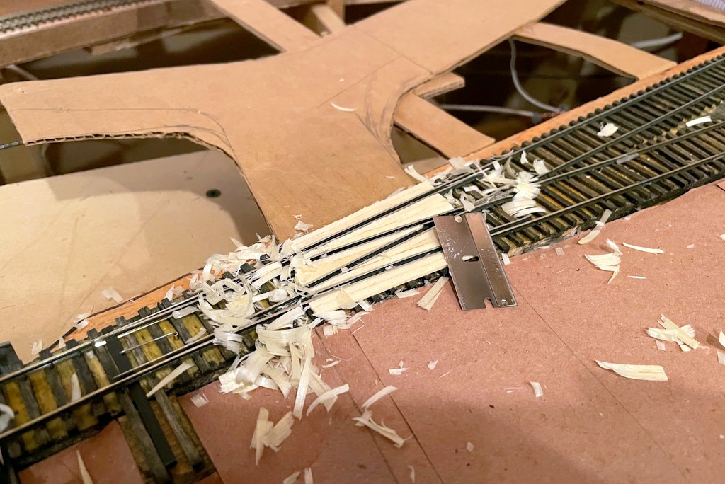
Just a quick progress update. After procrastinating and working on a semaphore, a station mock-up, and even safety signs, I’ve finally started work on the scenery again. Using the same “paper shell” method of cardboard strips, red rosin paper, and lots of hot glue, I’ve been able to get the wye in St Charles filled in with the basic land form. Of course, putting in the cardboard underlayment for the roads got me thinking about grade crossings, so I had to pause again and put in 6 grade crossings using rails and wood. Pretty simple and nothing profound, but I’m happy with the way they’re turning out. I didn’t worry about vertical height of the wood initially, only horizontal placement. I used a razor blade to whittle the wood down to rail-height level (a little tricky and scary, but effective), then used a little sandpaper and a “bright boy” track cleaner to ensure the wood doesn’t stick up and cause electrical contact issues.
That’s all for now.
The basic scenery form is now almost done in St Charles–just some cardboard strips and red rosin paper… and lots of glue
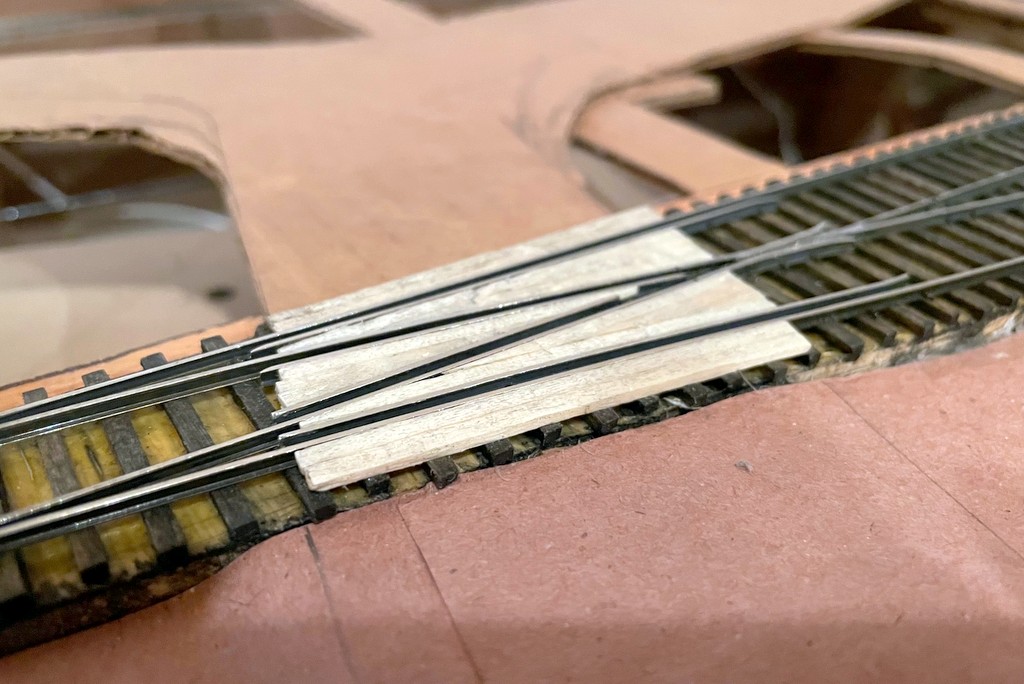
Step 1 of a complex grade crossing–adding the guard rails (extending the existing guard rails in this case)
I used full size ties and wood glue to fill in between the guard rails, then used a razor to whittle everything down to rail-height
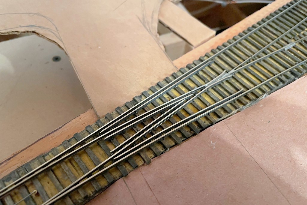
The almost finished crossing after whittling, sanding, and scribing lines and bolts with an X-Acto blade and thumbtack
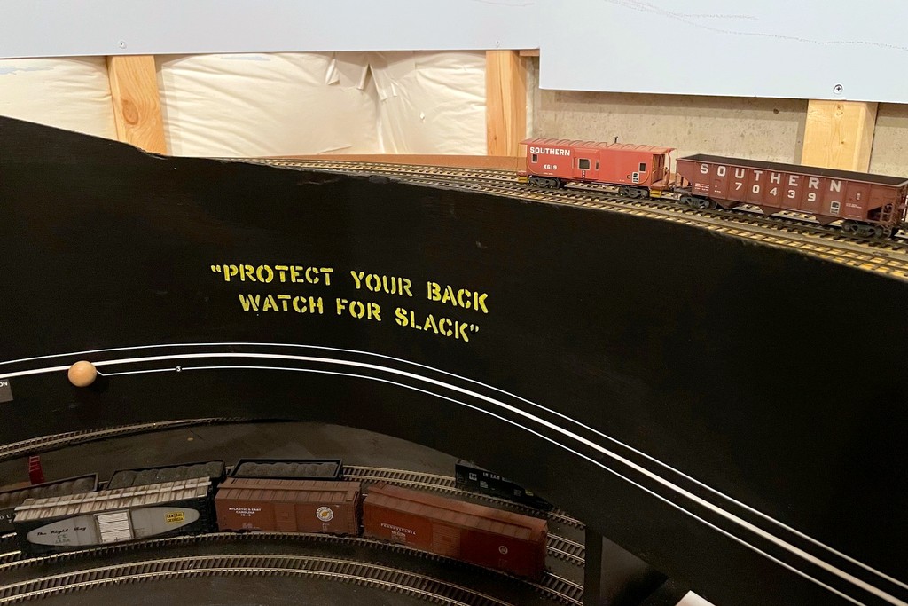
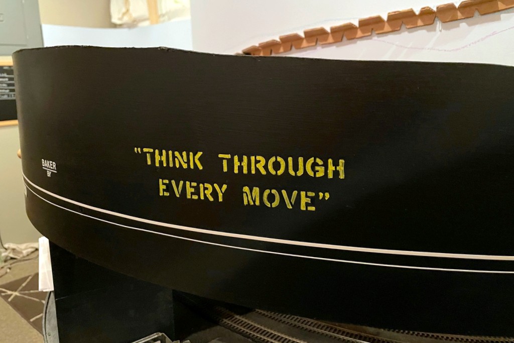
“Protect Your Back Watch for Slack” safety slogan in the yard at St. Charles
Real railroaders are inundated every day by safety slogans. This focus on safety appears to have ramped up in earnest in the 1970s with slogans appearing on all sorts of company publications, in shops, and on rolling stock like cabooses. I thought it would be fun to bring some of these prototypical safety reminders to the layout.
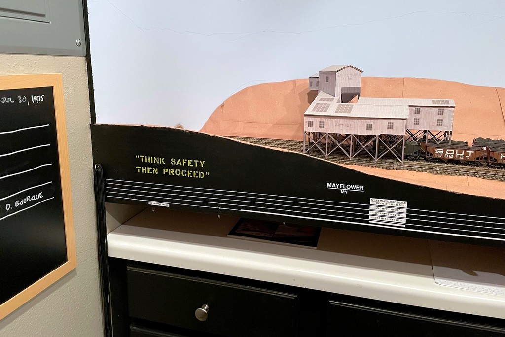
Safety slogan “Think Safety Then Proceed” occupying a corner at Mayflower
The first step was to determine what kind of safety slogans the Southern used. I found the best place to find them was just above the steps of a caboose, so I pored over hundreds of photos of Southern cabs, zooming in over the steps to see what slogans I could make out. I was able to capture more than a dozen slogans including the following:
“SOUTHERNERS THINK SAFETY”
“WATCH FOR SLACK”
“GET A GOOD GRIP FOR SAFETY”
“GET ON AND OFF AT SAFE SPEED”
“ON OR OFF CHECK FOOTING”
“THINK SAFETY THEN PROCEED”
“LIFE GOES YOUR WAY WITH SAFETY”
“SAFETY – GO FOR IT”
“DISMOUNT AT SAFE SPEED”
“PROTECT YOUR BACK WATCH FOR SLACK”
“THINK THROUGH EVERY MOVE”
“GET A GOOD HOLD ON SAFETY”
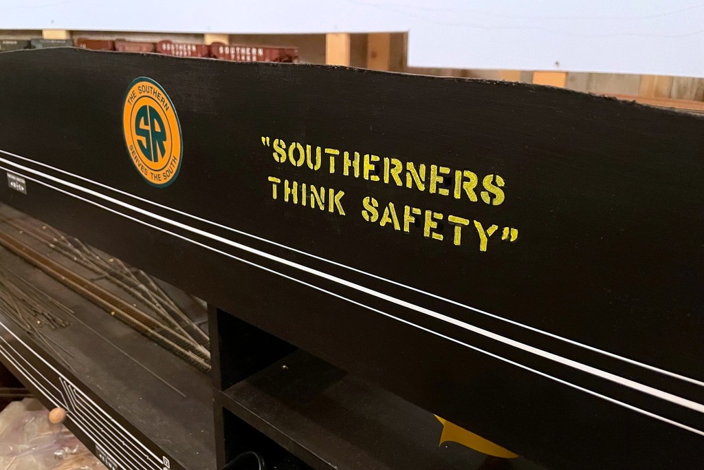
This safety slogan is the most unique to the Southern, so I placed it next to the Southern logo on the fascia
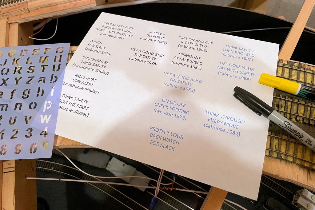
Armed with these slogans, I headed off to Hobby Lobby to pick up the closest lettering stencil I could find in the 3/4″ size range, a yellow paint marker, and a black paint marker – less than a $10 investment. I selected a few blank spots of fascia around the layout and used masking tape to provide a level reference line for the lettering. I just hand-held the stencil against the fascia, applied some yellow paint marker in the correct letter, and wiped the wet paint off the template. I carefully held a paper towel up to the freshly painted letter and dabbed it dry without smearing–this not only allowed me to move on to the next letter quickly, but it helped to created a worn and mottled look to the letters that I liked. Once the upper line was done, I measured and picked the middle point of the line, reset the masking tape for the lower line, and started with the middle letter for the lower line to keep things centered.
I decided to add the quotation marks as well. They appear on some of the slogans (not all), but I think it helps make it clear that these are pulled from somewhere instead of just being a random sign on the fascia. The template didn’t have the quote marks, so I used an X-Acto blade to make my own stencil in a blank spot on the plastic template. After things dried, I used a combination of the black paint marker and a sharpie to clean up around the edges. Finally, I used the Sharpie to draw in some extra stencil lines across the letters using pictures of actual Southern stenciling as a guide (for example, a line under the top part of the “T” and lines across the top and bottom of the “C” and “S”).
Ok, there’s one more project down that’s been rattling around in my brain and one less excuse to procrastinate on getting back to scenery…
This was a simple project that only required a list of slogans, a cheap lettering template, a paint pen and a Sharpie
This safety slogan is the most unique to the Southern, so I placed it next to the Southern logo on the fascia
Safety slogan “Think Safety Then Proceed” occupying a corner at Mayflower
This safety slogan seemed particularly appropriate for a switching-based layout
I put the “Protect Your Back Watch for Slack” slogan in the yard at St. Charles
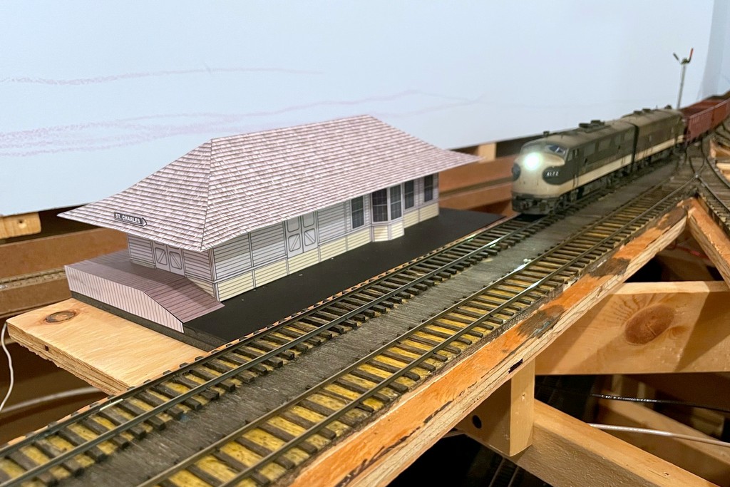
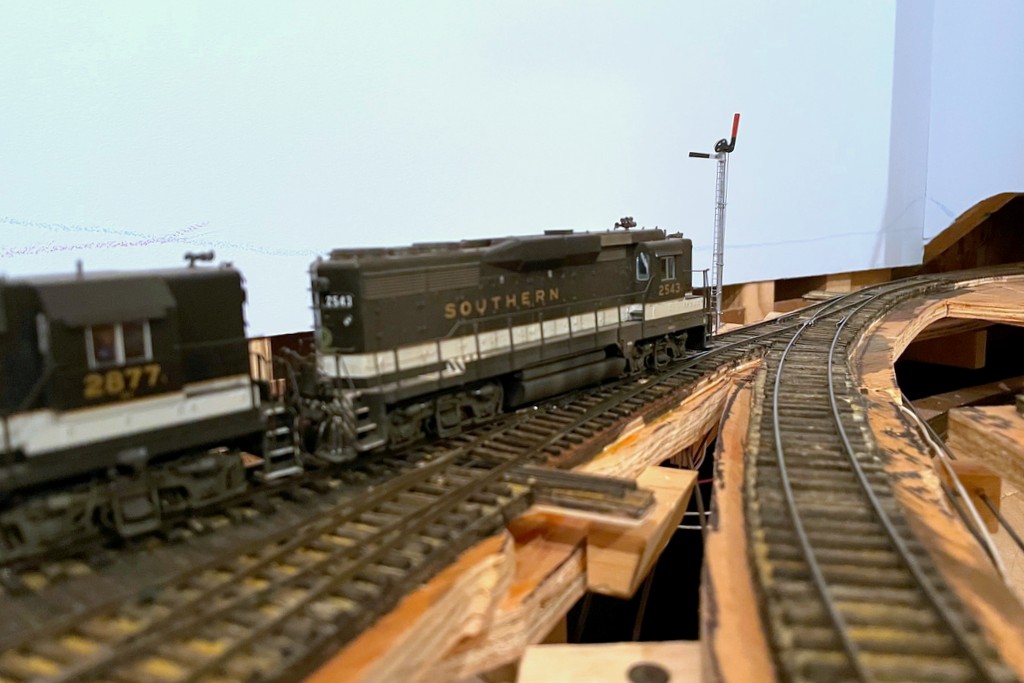
The St Charles local slows to pick up orders from the operator at the St Charles depot
This update is proof positive that I will do anything to procrastinate on building scenery… Of course, in my mind I’ve justified this delay as important because I need to be able to visualize the scene in St Charles before putting in the basic landforms. Sure, let’s go with that very logical explanation!
Several months ago I shared my plan to build mock-ups of the major structures on the lower level, the first of which was the Mayflower tipple which has appeared in many updates since it was built. I don’t want to build the permanent structures until construction on the upper deck is complete, but I’d like to have some of the key buildings represented both to visualize scenes and to give operators something better than just a block of wood to represent the buildings they’re working. Creating these mock-ups also requires me to build scale drawings (in MS PowerPoint) which, in theory, will make it MUCH easier to build the actual structures down the road. Of course, PowerPoint makes it easy to add colors and textures, so why not?
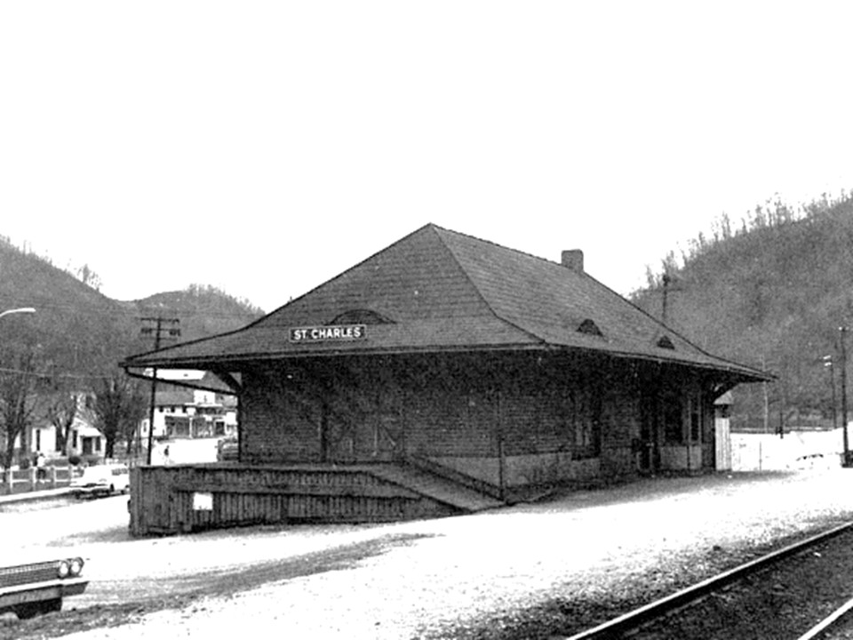
One of the few pictures I’ve found of the St Charles depot–it was darker, but I lightened it to see more of the details (photographer unknown, please tell me if you know so I can give proper credit)
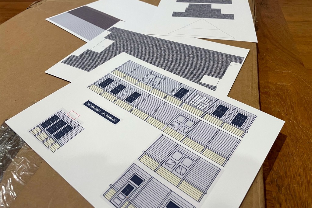
The St Charles depot burned down in the late ’70s, so there are very few photos of it. I worked with a couple of grainy shots and one grainy overhead image to get the basic size and layout. I used scanned plans from other Southern stations to get basic dimensions and features and to serve as a template for building the drawings in PowerPoint. I don’t have the space to model the station full-size, so I aimed for about 90% to scale on the length and about 70% on the width. The toughest part of the drawing was getting the cut angles for the roof right in a flat rendition so I could get the 3D shape correct. It required some trigonometry that made my brain hurt, but in the end I got a double-pitched roof with 22- and 35-degree slopes, pretty close to the drawings of other Southern stations. I omitted the curved roof windows for the mock-up as they would have been a pain and aren’t important to visualizing the scene. The detail like windows and siding is just lines and shapes drawn in PowerPoint, and the roof shingles are a texture I found online. Don’t ask me why the door on the track side of the station is suspended on the wall with no ramp or dock, but as you can see on the prototype photo, it is!
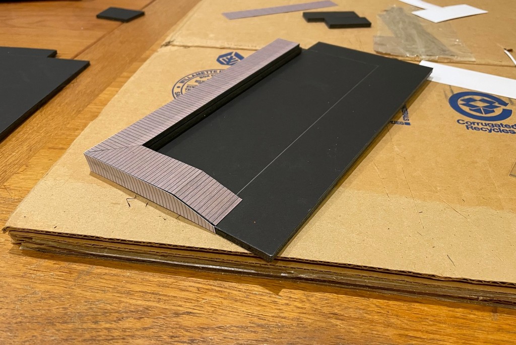
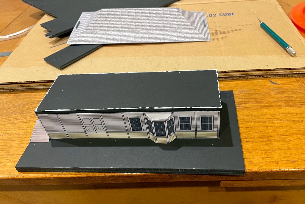
I used 1/4″ foam core to give stiffness to the basic structure
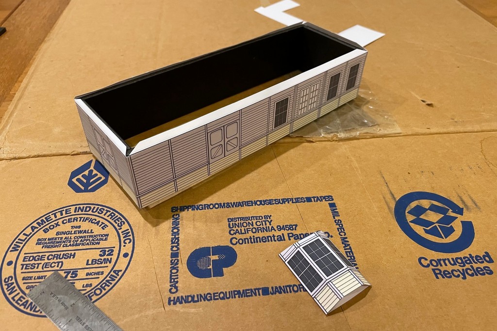
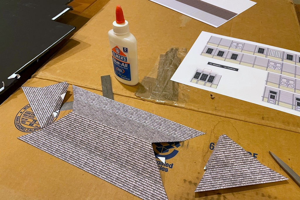
I learned from the Mayflower tipple that using ordinary paper results in the glue bleeding through and staining the color, so I printed this one on heavy paper, almost card-stock and about as thick as my printer would handle. I cut the basic walls out of 1/4″ foam core using the drawings as a template to give it rigidity, but the roof is just the card stock. I built a base and the loading dock on two sides using layers of foam core and covered parts with print outs of boards and vertical siding cut to shape. A couple of tiny “ST CHARLES” signs made from folded paper completed the mock-up. Everything is assembled with basic white glue. After it dried, I set it on a piece of plywood I attached to the sub-roadbed using spacers to level it on all sides–I figure this will make it easier to install the final structure level.
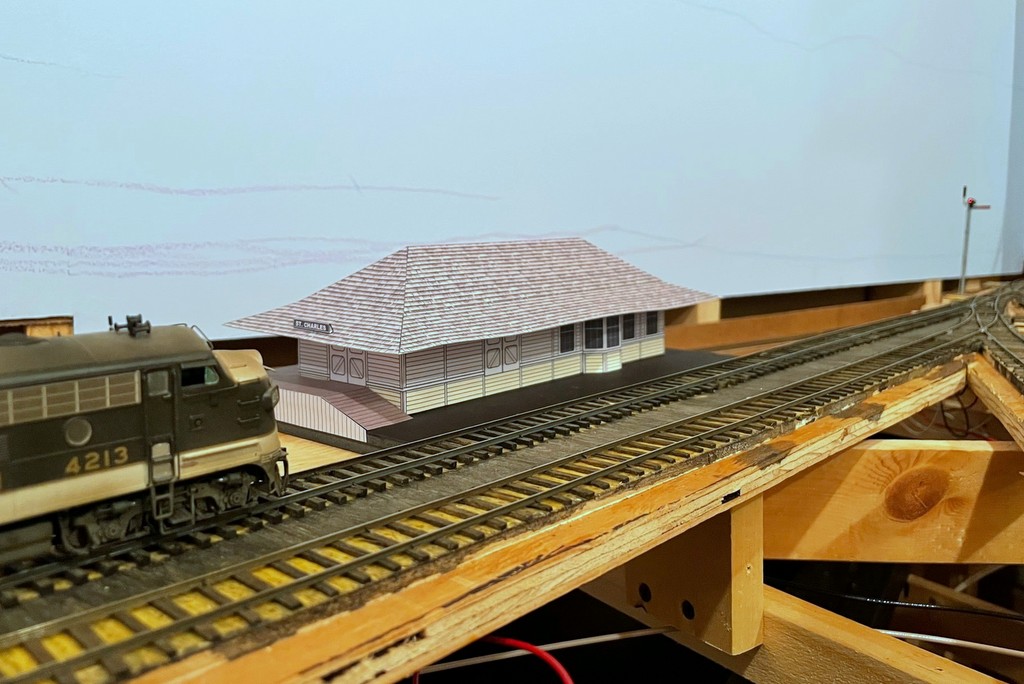
Now that it’s in place, I see that I need to raise the roof probably another 3/16″ which will be easy enough to fix in the final version [update, I raised the roof another 3/16″ as seen in the first photo, and it looks better]. For now, though, it’s great to have something anchoring the scene in St Charles, and I’m sure it will perform many years of dutiful service as I’m very slow. Oh, and if you know what colors the St Charles station was painted (there are clearly two), please leave a comment!
Here is the set of scale drawings flattened and printed on heavy paper
The toughest part of the drawing was getting the angles of the roof right… trigonometry in 3D… my brain hurts, but it worked!
I used 1/4″ foam core to give stiffness to the basic structure
The base and loading dock are made from layers of foam core with paper boards cut and glued to the edges
The original mock-up with the roof too low… didn’t look quite right
Bird’s eye view of the station scene–the track in the back will be hidden by a hillside behind the station
After letting the mock-up sit for a day, I decided to “raise the roof” to get it closer to prototype. I carefully removed the roof with an X-Acto blade and cut a piece of 1/4″ (really 3/16″) foam core to raise things a bit
The St Charles local slows to pick up orders from the operator at the St Charles depot
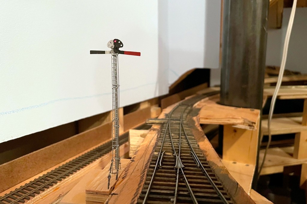
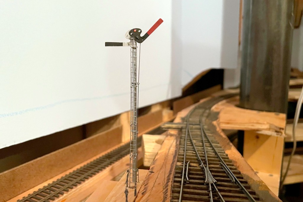
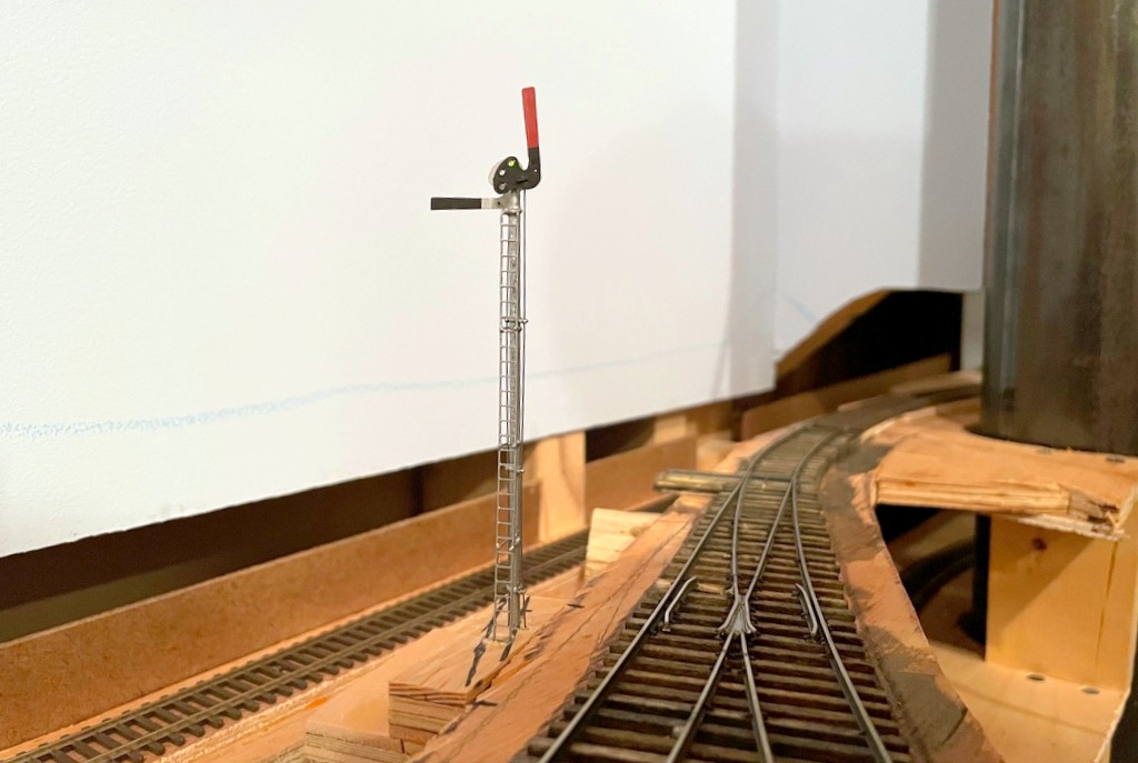
The semaphore in action indicating the St Charles Local has no orders to pick up before proceeding eastward to AppalachiaBlade down and red light indicating both east and westbound trains must stop at the station to sign for orders
I had one major project to complete before completing the scenery base on the lower level, and that was the train order signal in St Charles. I’ve been putting this off for a couple of reasons. First, I’ve never made a full working semaphore before, so I wasn’t sure exactly what I was taking on–the dwarf semaphores I made a while ago gave me a significant head-start, but this was much more complex. Second, I don’t know exactly if the Southern used a semaphore in St Charles – or if they did where it was located – so I was hopeful my procrastination would result some evidence. Alas, I finally just had to bite the bullet and build the thing! Yes, I know there are commercially available semaphore kits, but what would be the fun in that? I’m a glutton for punishment, and I had a bunch of brass stuff laying around, so why not try to scratchbuild one?
I know with 100% certainty that the station in St. Charles had an operator who passed train orders to Southern and L&N crews working the branch. There is both photographic and timetable evidence for this. In the era I model, it was typical for a train order station to have a three-color signal of some sort indicating “red” (stop to sign for orders), “amber” (slow down to pick up orders) or “green” (no orders – proceed), and a three-position semaphore was common. On most stations, the semaphore is built right alongside the station’s office with the control levers inside the station. However, pictures of the St. Charles station clearly do NOT show an adjacent semaphore or any other type of signal. The only thing I can think is that the Baileys Creek Branch to Mayflower cut off the St. Charles main a couple hundred yards geographically south of the station, and train movements on this branch were controlled by the station–perhaps the signal was closer to this junction to allow train crews to see it an heed from both the St. Charles and Baileys Creek Branches. So, that’s what I chose to model!
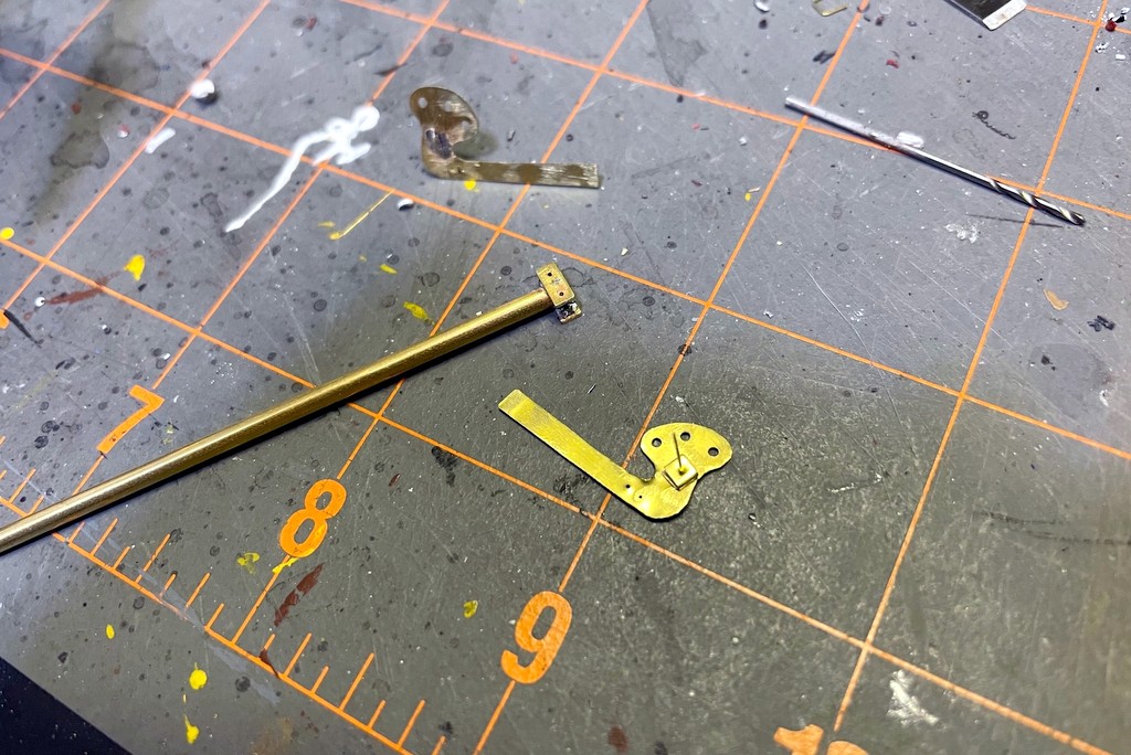
After finishing the semaphore blades, I attached a .015″ brass wire via solder and made a spacer from brass strip folded on itself. I used the same brass strip to make swivel bases for the blades on both sides of the pole
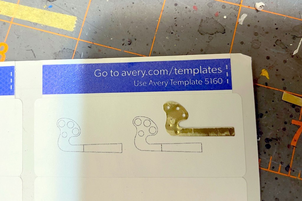
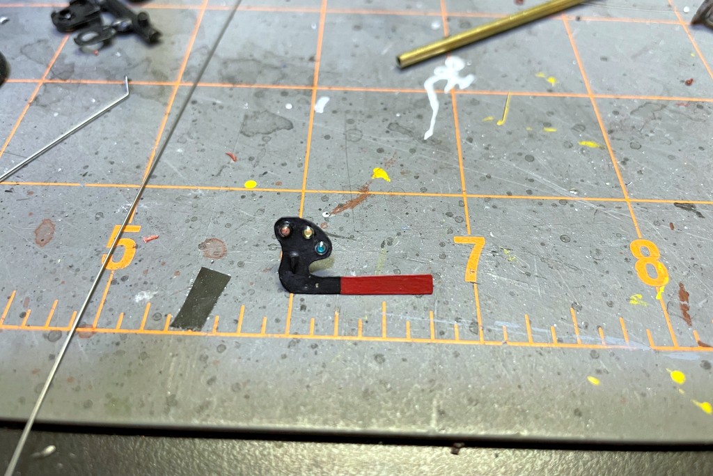
Like my dwarf semaphores controlling access to the coal branches, I wanted the semaphore to be fully operational including lights, blade movement, and fascia-mounted controls. The first job was making some semaphore blades. I did this by making an outline of an upper-quadrant blade in PowerPoint, scaling it to 1:87, and printing it onto a label. After attaching the label to some thin sheet brass, I drilled holes for the lenses, pivot point, and control rod and cut out the blade with scissors, using a file to clean things up. I soldered on the pivot rod, .015″ by bending one end, inserting it through the hole, and soldering it to the blade face. Next I added a small spacer for the blade onto the rod made from a piece of small brass bar bent on itself with a hole drilled through. I painted the blades flat black and insignia red for the blade end. The back of the blade got some silver Sharpie following pictures I’ve seen of other Southern stations. The lenses are just short pieces of fiber optic with one end melted into a round shape using a soldering iron (just hold it near the end of the fiber optic), attached with CA and colored with kids markers.
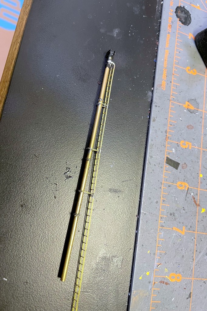
The next step was to add the brass ladder stock and connect it to the mast with U-shaped .015″ brass wire
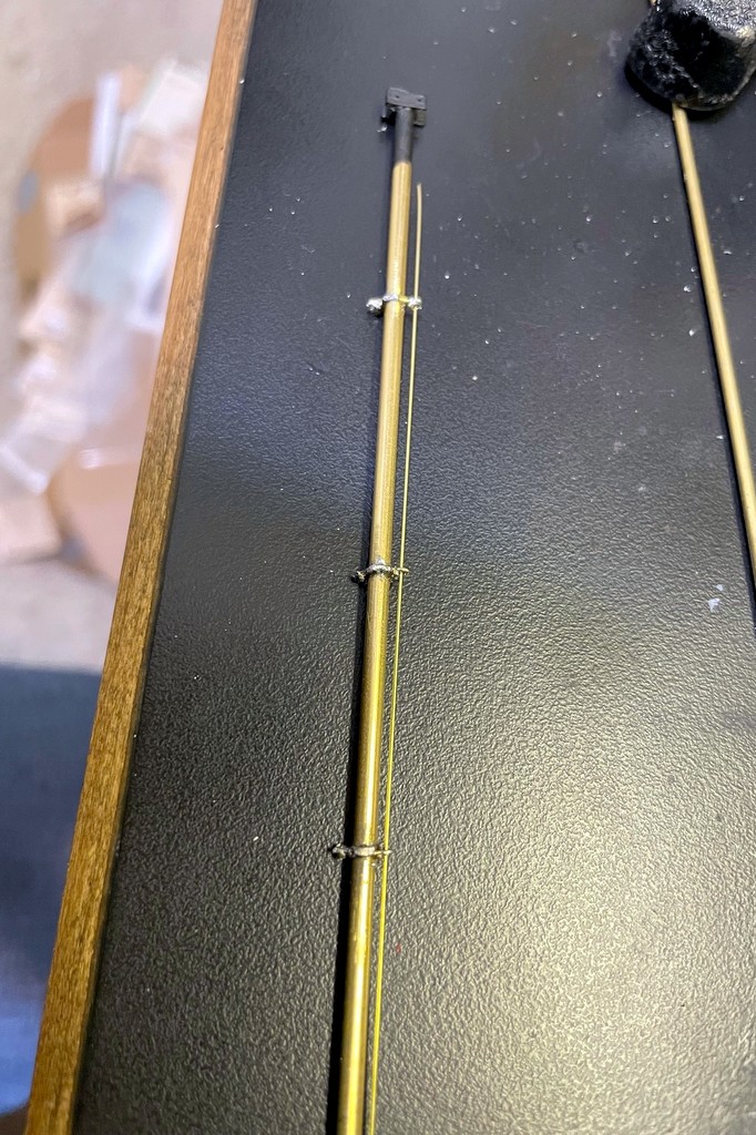
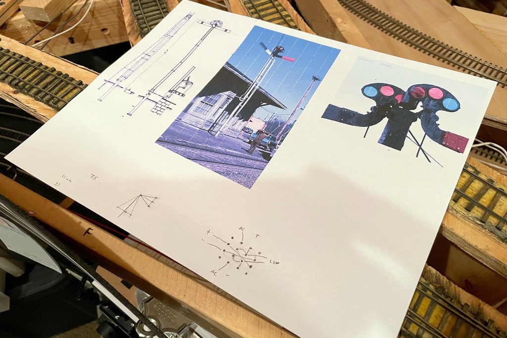
The mast is a piece of 3/32″ brass tube. I made two mounting plates for the top out of brass bar, filed flat spots onto the tube, and attached them via solder. Next I added some guide loops for the rods that would go from the ground to the blade. I bent something resembling the shape of Saturn out of .015″ brass wire and soldered it tightly around the mast, using a semaphore mast diagram printed to scale as a guide for positioning, three guide loops total. This resulted in two U-shaped loops, one on either side of the mast. I finished the loops by soldering a small piece of wire across each U to make a smaller hole to the outside away from the mast. My soldering skills are not great, so this was a lot of ugly blobs until I took a file and cleaned things up. I added a piece of brass ladder stock by connecting it to the top with solder, bending it, and making U-shaped supports out of .015″ brass wire which I soldered into place in three locations and cleaned up. I painted the mast assembly flat black and then used a combination of silver Sharpie and silver paint to finish it.
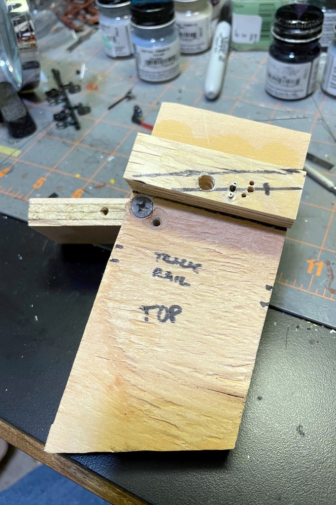
Now I was ready to put the blades onto the mast. I fashioned some control rods from .015″ steel music wire, inserted them into the blade holes, and ran them down the guide loops on each side. After inserting the blade pivots into the mounting plate, I bent the brass rod 90 degrees to hold each blade in place while allowing it to pivot freely. I made the base from scraps of plywood (see pictures) and drilled a 3/32″ hole for the mast, two adjacent 1/16″ holes which I lined with 1/16″ brass tubing for the control rods, and a larger hole for the ladder to slide into. I press fit the mast into the holes with the rods going through their brass tubes. Then I ran a piece of fiber optic cable down the tube. I first tried to file one end of the fiber optic at an angle to get it to shine through the blade lenses, but this didn’t work well. I ended up holding the fiber optic over a spare piece of 3/32″ brass tube which I heated with a soldering iron. When the tube got hot, the fiber optic bent itself over the tube in a perfect curve which still conducted light well. A little more heat to make a rounded lens at the end, and I had my “light” for the blades.
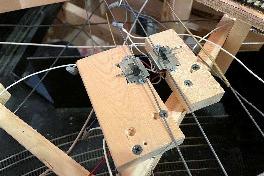
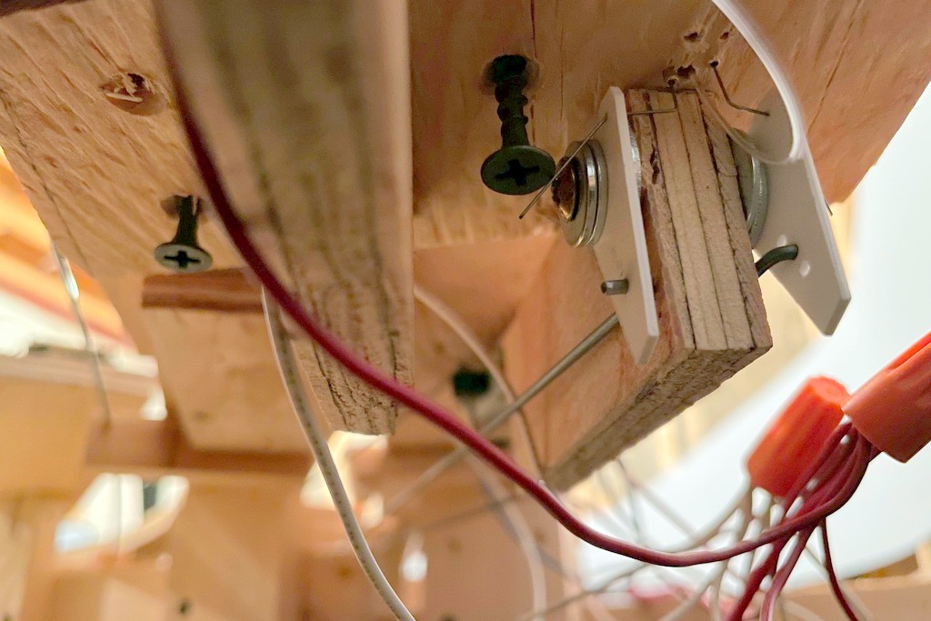
Here are the mechanisms made from 3-way slide switches. Not only do the switches route power to the bi-color LEDs, it also connects the lever to the signal mechanically and provides the detents for movement
I wanted to use .062″ steel music wire (the same stuff I use for manual turnout controls) for the fascia-mounted control rods, so I crafted two triangular levers out of thick styrene hinged at one corner to convert the horizontal control rod movement into vertical movement for the blade control rods. I covered this in some detail with the dwarf semaphores, so I won’t cover it again here. With the mechanism in place, I mounted the base and semaphore assembly in place on the layout. Next, I worked on the control rods made from 36″ pieces of .062″ steel music wire. Where they would cross through benchwork, I drilled 2/32″ holes and lined them with brass tubing. I was able to get a pretty good bend in the control rod without it kinking this way.
Here’s the finished semaphore from levers and lights to the blades in the background
The heart of the control rod mechanism is a 3-way slide switch. I bought a handful of these for the dwarf semaphores because of their longer throw, but it turns out they were exactly what I needed to control both the throw and the lights for the full semaphore. I’m using 2-lead, bi-color red/green LEDs for the lights. Controlling the red and green is easy enough with DC and crossing the +/- leads on two of the poles on the switch to get the red and green on the end throws of the switch. For the amber, I wanted to use the AC current from my track power. It took a bit of thinking through the use of the 16 leads (it’s a 4-pole slide) to figure out how to route both AC and DC power to the same LED without ever crossing the streams, but the arrangement seen hand-drawn on my cheat sheet (see gallery below) works well. I secured the rods to the semaphore to the slide switch by bending them 90 degrees and inserting them into a hole drilled through the switch control. A second rod inserted through a second hole in the switch control was run through a piece of 3/32″ brass tubing to the front of the fascia where I capped it off with a wood ball (smaller than the ones I use for switch controls so operators can tell the difference).
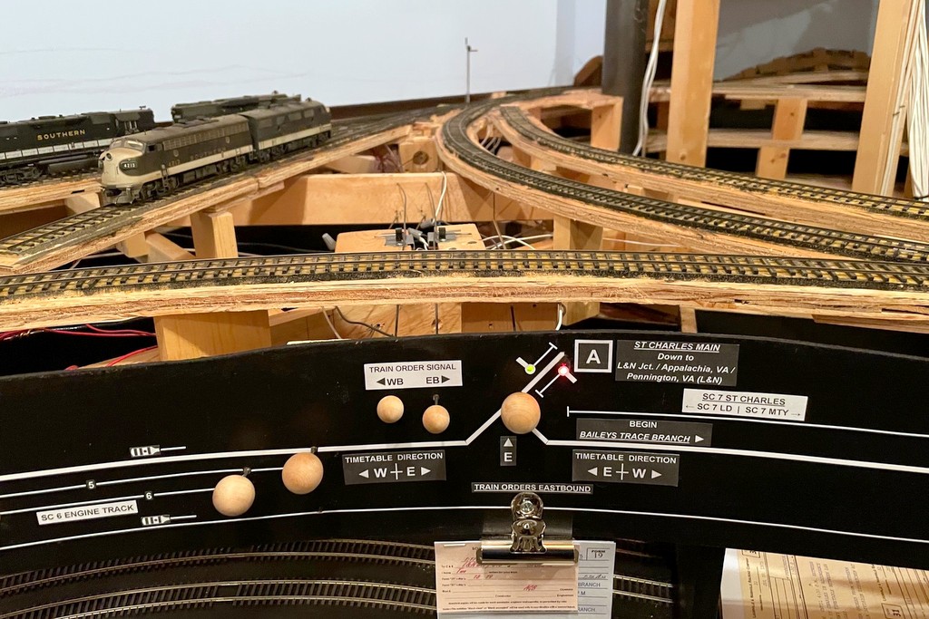
The final step was to run LEDs from both switch mechanisms to the fascia where I used stick-on letters and graphic tape to make a little drawing of a semaphore in each direction alongside the track diagram–the operators can look on the fascia to see the color indication if they don’t want to use (or don’t understand) the blade positions on the layout. Finally, I added a second clip to hold orders under the fascia so that the old clip is now “train orders westbound” and the new clip is “train orders eastbound.” So far I’m really happy with how the semaphore looks and now it operates, and it was really fun to build. I know it will add yet another aspect of prototypical operations to the layout as crews now have to read signals to see whether or not they need to pick up orders.
I made a diagram of a semaphore blade in Microsoft PowerPoint then printed it in HO scale onto a label. This made it easy to attach it to the sheet brass, drill holes, and cut it out with scissors
After finishing the semaphore blades, I attached a .015″ brass wire via solder and made a spacer from brass strip folded on itself. I used the same brass strip to make swivel bases for the blades on both sides of the pole
One of the finished blades painted black and red with no stripe per Southern custom. The lenses are short pieces of fiber optic with one end melted round by holding it close to a soldering iron. The color is just marker
I made guides for the blade control rods using .015″ brass wire bent into a “flat Saturn” shape around the mast. The control rod is .015″ steel music wire
The next step was to add the brass ladder stock and connect it to the mast with U-shaped .015″ brass wire
The base plate is simple. Under the signal is a second layer of plywood to get the signal to track level. Holes for the mast, rod guides and ladder are in the middle (the right-hand holes are mistakes). The plywood fin will support the levers to connect the manual control rods to the rods going up to the blades
Here’s where the lever rods meet the rods going up to the blades. The multiple holes in the styrene allow the rod to be repositioned for more or less throw (I ended up using the top hole on both to get more throw)
Blade down and red light indicating both east and westbound trains must stop at the station to sign for orders
Blade halfway and amber light indicating the eastbound train should slow to pick up orders (handed up by the operator) but doesn’t need to stop and sign for them
Blade up and green light indicating no orders for the eastbound train
Here’s the little cheat sheet I made up. I scaled the blueprint to HO and used the sheet to plot my throw and my wiring for the 3-way slide switch
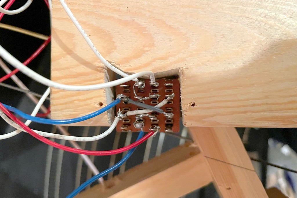
This is the finished wiring of the 3-way slide switch. The ends connect to DC for the red and green colors of the bi-color LED. The middle attaches to AC (DCC track power) for the amber (rapidly flickering red and green)
Here are the mechanisms made from 3-way slide switches. Not only do the switches route power to the bi-color LEDs, it also connects the lever to the signal mechanically and provides the detents for movement
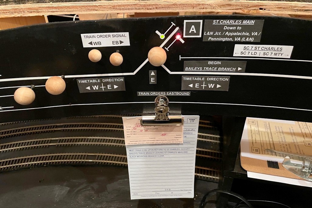
Here’s the fascia end of the semaphore including levers (WB in, EB out), indicator lights along the track diagram, and the clip for the orders which necessitate the signal
Here’s the finished semaphore from levers and lights to the blades in the background
The semaphore in action indicating the St Charles Local has no orders to pick up before proceeding eastward to Appalachia