Monthly Archives: April 2020

Seeking Opinions – Layout Name Change

Up to now, I’ve called my layout the “St. Charles Branch.” While this is technically accurate, I’ve struggled with it a bit because it sounds more like a property in a Monopoly game than a rugged piece of coal-hauling railroad. Perhaps I have delusions of grandeur and want a name that’s a bit more grand like “Allegheny Midland,” “Ohio Southern,” “Virginian & Ohio” or “Cat Mountain and Santa Fe.” Of course, these are/were MUCH larger freelanced layouts, but small layouts can still do great things, so why not? . . . I’m kicking around the idea of changing the name to the “Black Mountain Railway.” The logo would look something like this.

Black Mountain Railway Logo

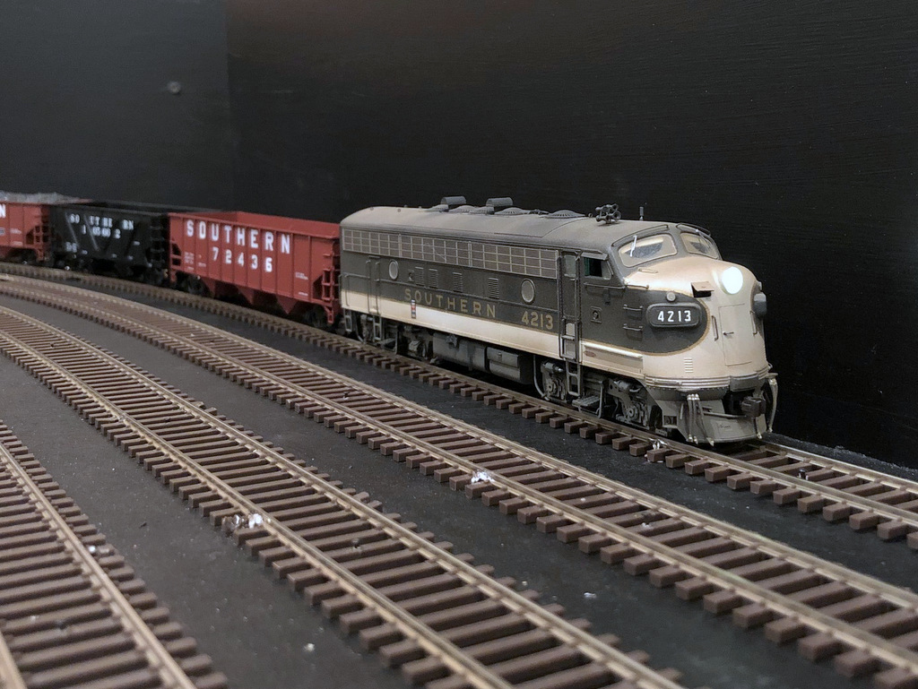
Why “Black Mountain?” First, Little Black Mountain is the name of the ridge that divides Virginia from Kentucky just a mile north of the end of the St. Charles Branch. The Black Mountain Railway was also the name of the first railroad to lay tracks in the St. Charles area (see prototype history). Even though the Black Mountain Railway was purchased by the Virginia & Southwestern and later the Southern Railway, the Southern mine run that worked the end of the St. Charles Branch was alternately refered to as either the “St. Charles Switcher” or the “Black Mountain Local” until at least the NS merger.

The draft logo for the layout makes it clear the focus is the Southern Railway, but it includes a little splash of color for the L&N. The shape is a black hexagon symbolizing coal, machinery and hard work (like a nut and bolt). In addition to the words “Black Mountain Railway” in Southern Dulux Gold on the hexagon are two yellow circles–while good for filling some empty space, they’re also reminiscent of the “yellow ball” markings that adorned many of the hoppers used in captive service on the line. Ok, maybe I’m stretching the symbolism a bit far, but hey. Oh, and if you’re thinking it’s a bit reminiscent of the Pittsburg & Shawmut logo, yes, it is! . . . and a hexagon is a lot easier to cut out than a circle. . .

Anyhow, I’d love your thoughts on the name change–please leave a comment below!

Staging Level Plan

It occurs to me that I’ve been sharing all these pictures that show pieces and parts of the staging level, but I’ve never shared a drawing showing the staging plan.

St Charles Branch Staging Level Plan

Staging takes up almost the entire space below the lower level. The notable exception is a large cabinet in one corner that houses tools and supplies and a narrow space next to the cabinet dedicated to the DCC command station, booster, and computer connection. Adjacent to the DCC command station (currently a Digitrax Zephyr Xtra) is a 19″ section of track separate from the layout for programming locomotives. This area also houses two short connected tracks for storing locomotives not in use for a given ops session–I figured this was better than handling them all the time.

The rest of the level contains the two staging yards for the Southern and L&N, respectively. Southern staging, representing Appalachia, VA, consists of three staging tracks on a reversing loop with tracks of 21+ feet. Inman represents the upper end of Appalachia Yard (as it did in real life), and I’m using this moniker to differentiate the “business end” of Appalachia from the reversing loop connection end. A forth track snakes around the reversing loop to form a continuous running connection on the other end of the layout where the helix goes up to St. Charles. I plan to use this to break in new locomotives and to entertain kids–in a pinch it can be used as a fourth Southern staging track.

Staging Level Track Complete
Tracks on the staging level are now complete. The last piece was the 4-track L&N staging yard shown here.

Under St. Charles is a 4-track, stub ended staging yard for the L&N which represents Pennington, VA where the short Pennington Branch left the L&N’s Cumberland Valley main to connect with the Southern at Pocket, VA (technically L&N Jct), not far from St. Charles. L&N tracks are 13 1/2 feet long, plenty long for the single locomotive and short string of cars that usually plied these rails. Four tracks is about three too many, but this will allow some “fiddle staging” for less commonly used cars (e.g., boxcars) and hoppers from other eras.

Hope this helps to visualize things better!

Layout Wiring

Layout wiring on the St. Charles Branch is simple yet very robust using common household wiring supplies. First, I’ve divided the layout into six blocks: four “main” blocks (1. Staging, 2. St. Charles, 3. Mayflower, 4. Upper Deck), and two reversing sections (1R. Staging loop, 2R. St. Charles Wye). Even though I don’t have a power block distribution circuit yet (like a PSX4), I’m wiring the layout for that eventuality and just tying all the blocks together at the command station as an interim.

Feeders and Bus Pigtail Connections
Feeders are connected to the wiring bus via wire nuts connected to pigtails along the bus.

The bus wiring for each block is copper Romex wiring. . . that’s right, Romex, the 14 AWG copper wire you use to wire household sockets and light fixtures. It’s overkill, but it’s easy to find, comes in long lengths, and the current loss for DCC applications is pretty much zero. I strip the outer sheathing, remove the bare ground wire, and use the black and white wires. I run them under the track through holes in the benchwork separated by about 2.5″. Lesson learned: if running the bus for two blocks side-by-side, make sure you label each about every other piece of wood to avoid cross-wiring blocks later.

I drop feeders at least every 5 feet, so on every 2-5 feet of bus wiring, I’ll strip off about 1″ of insulation and make a “pigtail” if you will using a length of 4″ of the bare copper wire (Romex ground wire) wrapped tighly around the bus core about 3 turns and soldered. I leave about 1″ of copper sticking off either end and cap it with a wire nut. I separate the pigtails for the white and black wires by about 4-6″ to avoid accidental contact of exposed wire.

Wiring Feeders
Wiring feeders from the rails to the bus under the layout. The gray plug marks the spot of connection to make it easy to cut wires to the right length.

Finally, the feeders. As mentioned, I try to drop them every 3-5 feet of rail. For bulletproof operation, every single rail on the layout is directly connected to the bus either through its own feeder or a single soldered joint to the rail next to it that’s connected to a feeder (no trusting rail joiners to carry current and signal). I drill the holes first, then drop pieces of 18 guage stranded wire through to connect to the bus. You’ll notice in the picture above the layout the little gray plug. I use this to mark the location of the pigtail under the layout so I can accurately cut the feeders to length, leaving about 1.5-2″ extra length to account for vertical distance through the subroadbed and some wiggle room for orienting the feeder to fit into the pigtail. Because I hand-lay my switches, I need a LOT of extra feeders for the point rails and frogs (connected to switches under the layout).

To make sure I hit all the holes, I leave the sawdust from drilling them in-place until all feeders are in. I also work one color at at time; white for one rail, red for the other. Once all the feeders of one color are in place, I’ll tin them with solder and solder each to the rail. Under the layout, I’ll gather together 2-3 feeders, twist them together, and tie them to the pigtail using a common wire nut (size depending on the number of wires being tied together). A little tug ensures they’re solidly in-place.

I’ve found this method creates rock-solid wiring that’s easy to modify and troubleshoot–just disconnect and reconnect the wire nuts as needed. This method also works perfectly with Digitrax DCC which prides itself on picking a slower data rate that works well with non-high-speed wiring. If using on a different system, I recommend doing some testing first.

TRAINS!!!

Yesterday, my “benchwork” became a “layout” with the running of the first locomotive. Of course, trusty F7A 4213 was the first locomotive, and my boys did rock-paper-scissors to determine who would be the first engineer. My oldest won, but all three of us got a chance to run around the half of the staging level with completed wiring.

First Train on the Layout
This is the first train to run on the layout on April 17th 2020
Crew of the First Train
My two sons crewed the first train on the layout

Half a train, half a level, and no scenery in sight, but it was still a magical moment to see all that planning and work to this point pay off with a moving locomotive. As a bonus, the hand-laid switches performed well (despite not having their mechanisms in place yet), only a couple of protruding track nails on and excess solder in a couple joints (easily fixed) caused any issues.

I’m more motivated than ever to keep building!!!

Determining the First Engineer
My sons do rock-paper-scissors to determine who will be the first engineer

Bronze Spike Ceremony

Last night, I put down the “bronze spike” commemorating the completion of track for the staging level. Not that exciting in the big scheme of things, but it is a major milestone in the layout’s progress!

Staging Level Track Complete
Tracks on the staging level are now complete. The last piece was the 4-track L&N staging yard shown here.

The last piece of the staging level to be completed was the 4-track L&N staging yard representing Pennington, VA. This yard is stub-ended with tracks about 13.5 feet long. This is enough for a locomotive, cab, and about 20-28 hoppers. Based on photos, this will be more than adequate to represent the meager traffic the L&N hauled off the St. Charles Branch. I made it four tracks because I had the space, and this will give me some room to store trains and cars from “other eras” when not being used for a particular operating session.

There is still a bit more work to do before trains can run. I need to put in the switch control mechanisms and drop about 100 feeders to the main DCC track bus under the layout.

In the photo above, taken from the door to the layout room, you can see the Southern staging yard under the mess on the far left, the beginning of the Southern staging yard and end of the L&N stub tracks against the far wall, the Southern main linking staging to the helix (will occupy the open area on the right) along the right aisle, the L&N staging yard, and the continuous running connection entering along the right-hand wall–this last track connects to the Southern main via a switch just out of view in the lower right corner.

Southern Staging Tracks Complete

Another milestone today–the Southern Railway staging yard tracks are now complete! The yard, representing Appalachia, Virginia, consists of 8 hand-laid switches and about 40 pieces of flex track. The yard is three tracks on a reversing loop, one through track for mainline running (which can be used as a fourth staging track), and two short storage tracks for extra locomotives.

Southern Staging Tracks Complete
The Southern railway staging tracks representing Appalachia are now complete. The tracks form a reversing loop under the main helix.

The shortest staging track is about 21 feet long–that’s long enough for three locomotives, a cab, and 35-45 hoppers. . . should be plenty. A second, 4-track stub-ended staging yard with shorter tracks will help with L&N trains and holding excess cars.

Staggered joints for reversing loop
Here’s one of the insulated joints going from the yard lead to a staging track on a reversing loop. I offset the joints about 1″ which is recommended for better performance of the auto-reverser.

I also fixed a problem with this website where the smaller images weren’t linked to their full-size cousins–that’s remedied now if you’d like to get a closer view of previous post pictures. Thanks to Stuart Thayer for pointing that out!

Track Spacing Tool

I’m all about simple but effective solutions to construction challenges. One of those challenges is laying multiple tracks (like a yard) on a set spacing quickly. In my case, I have staging yards designed on 2″ spacing between track centers. There are several methods for spacing the tracks: I could just measure between them with a ruler every time I put in a nail, I could mark out spaces and draw a line for the edge of the next track, or I could make a really simple tool to make this process effortless.

Enter my fancy homemade track spacing tool! It’s a piece of 1×3″ lumber about 4″ long and cut 45 degrees on one end. . . I literally pulled it out of my scrap pile. Using a combination square, I penciled in a mark exactly 2″ from the edge on the bottom of the 45 degree face, then drew a second mark one rail’s width in from the first (closer than 2″); then I repeated this from the other side so it can be used in either direction.

Homemade Track Spacing Tool
Track spacing tool for 2″ centers made from a piece of 1×3″ lumber and some pencil marks

To use the tool, put the first track into place and secure it. When it’s time to lay the second track, simply place the tool along the inside edge of the outer rail of the first track, move the second piece of track so the inside rail lines up with the pencil marks, and secure it. Move the tool down to the next spot, line up the second track, and secure it–too easy. I’ve found using the inner rail of the first track works better than a smaller spacer between outer rails, especially on curves.

Southern staging yard spacing
I’ve decided to stop modeling the Southern and model the Pennsy main instead. . . Nope, this is the Southern staging yard laid out using recycled Atlas code 83 flex track from my last layout and my handy dandy 2″ track spacing tool

You can make the tool work for whatever spacing you need just by using different marks and different sizes of lumber. It sure ain’t fancy, but it’s elegant in its simplicity.

Oops!

Well, this is why you draw it out when you change the plan instead of keeping it in your head (it’s all there, right?). As I was laying tracks in the Southern staging yard, I couldn’t make the math add up on the number of tracks coming into the yard. I had five tracks and the ties laid for four switches (normally good math to go from one track to a yard), but I kept feeling something was off. . .

Sure enough, I had laid ties for one extra switch! In the original plan, the yard ladder took the Southern from one track to five (four staging tracks plus the lead for the reversing loop), but when I modified the plan in my head to allow continuous running, one of the staging tracks that was co-opted for the continuous run no longer needed to connect to the yard lead. Yup, one extra switch!

Oops - too many switches
Here’s what happens when you make a change to your plan in your head but don’t write it down. I ended up laying ties for one extra switch in the staging yard–glad I figure this out before laying rail!

Thankfully, I had only laid ties and not rail, so a little chisel, sandpaper and a Sharpie put things (almost) back to right. As those of you with layouts can attest, I’m sure this won’t be the last mistake I make, but I’m glad it was caught before I put a lot more work into something I’d have to tear out.