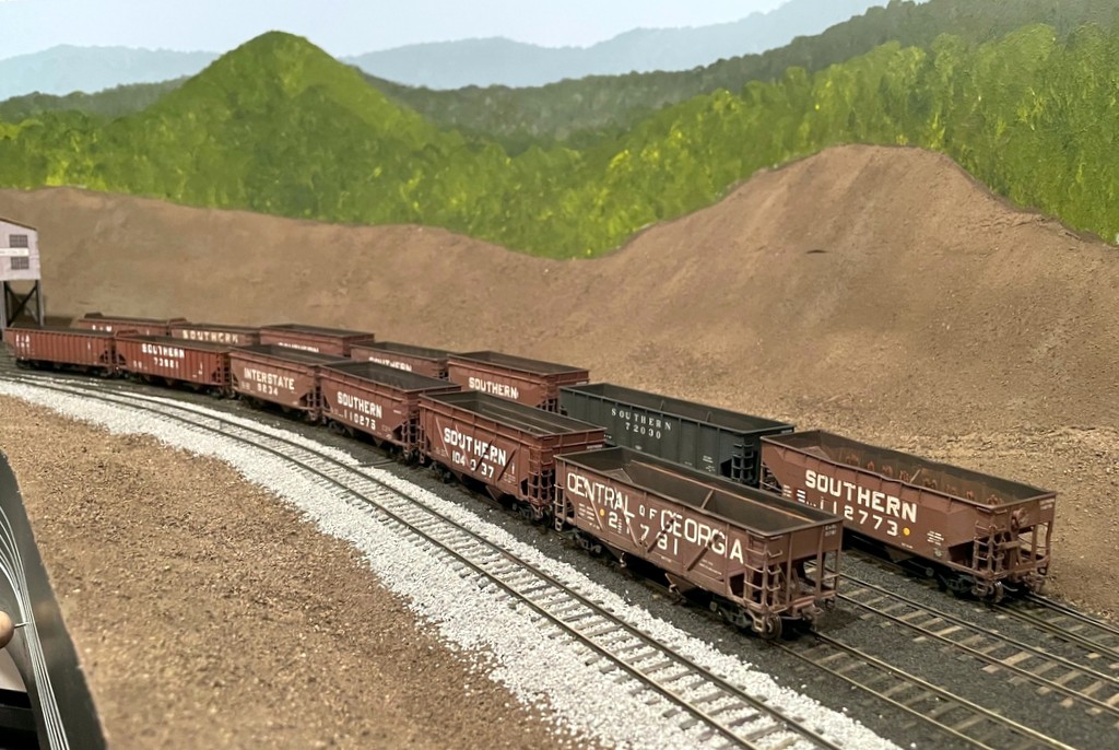
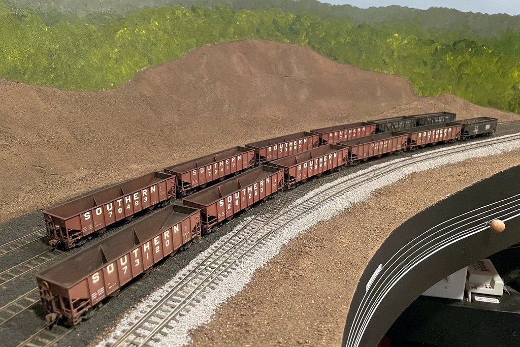
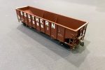
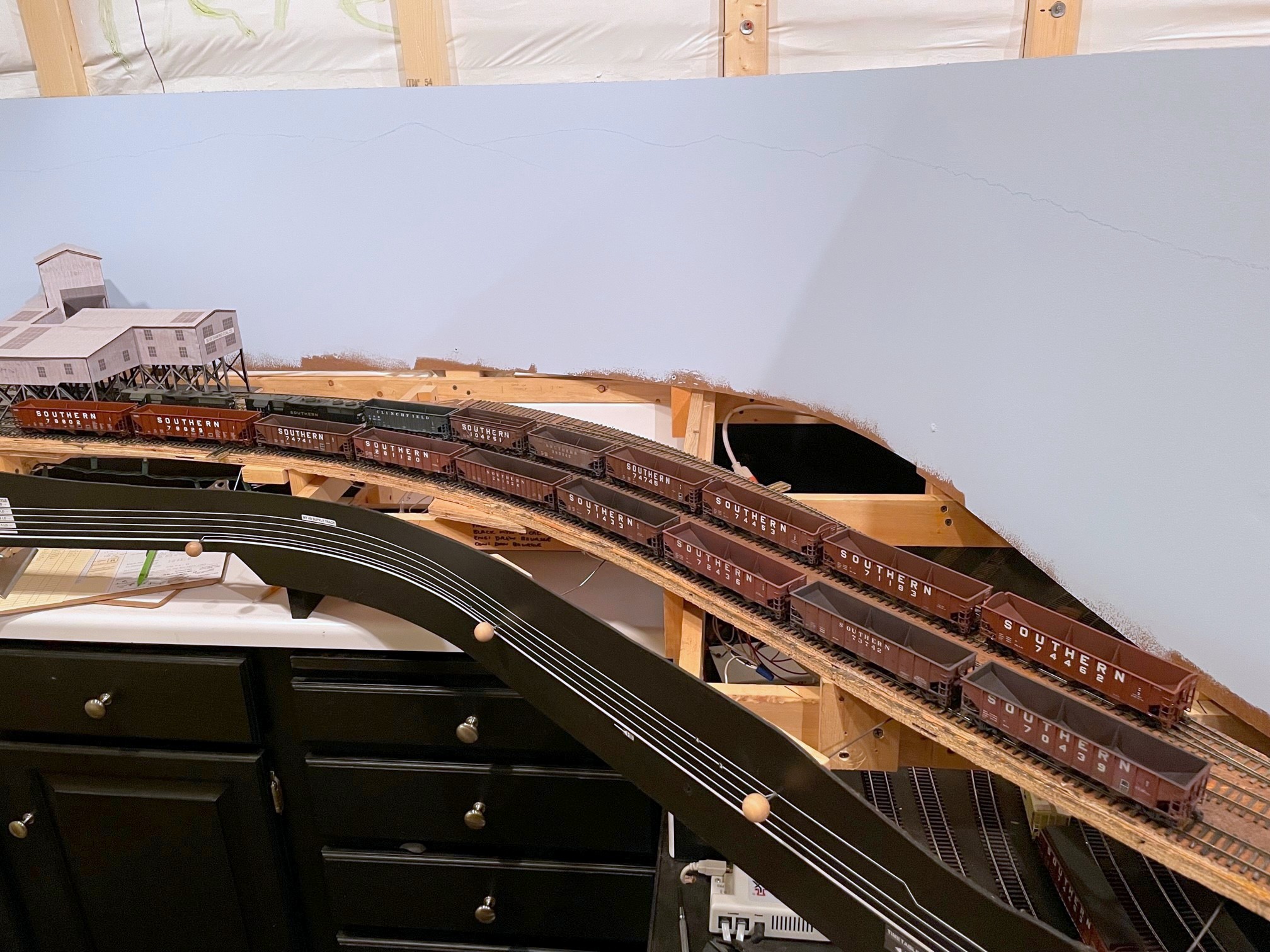
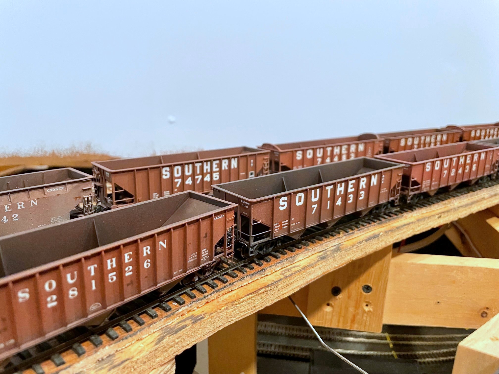
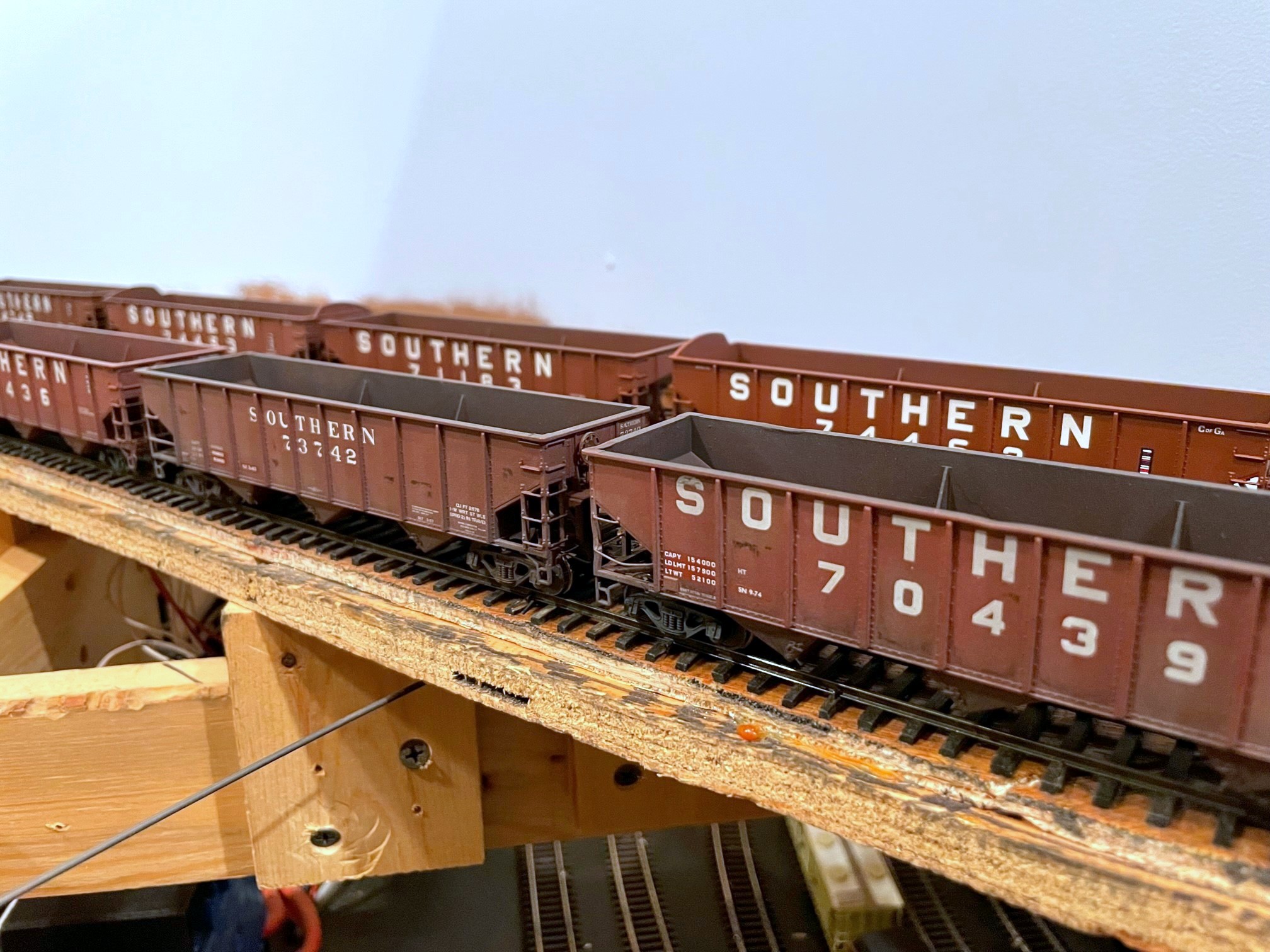
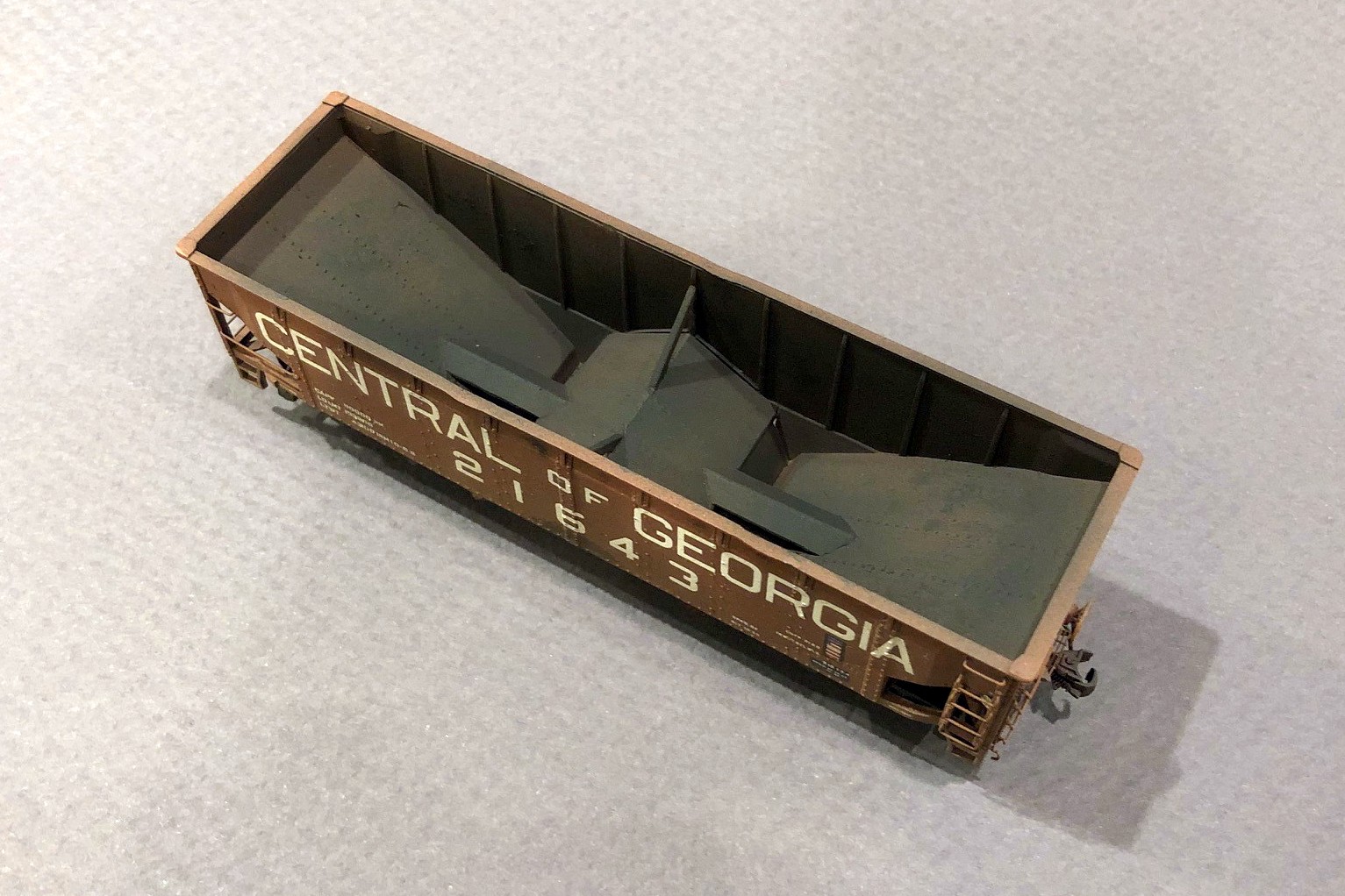
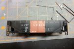
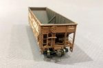
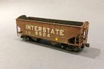
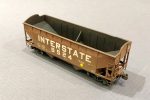
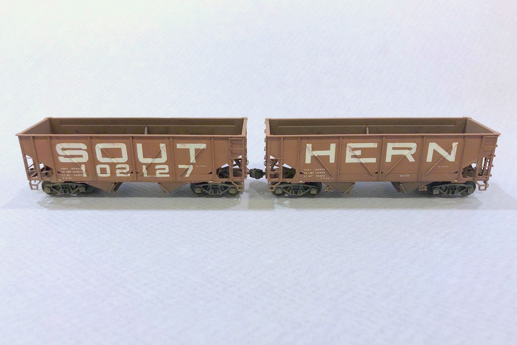
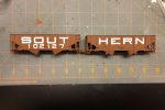
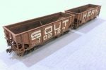
I’ve been on a hopper kick lately, so following close on the heels of the hopper class of January ’24 are these 13 cars comprising the hopper class of March ’24. They were actually built at the same time as the previous hoppers, but these were all custom paint jobs, so it took a while longer to paint and decal them. Among this class are several unique cars including two exact cars I’ve wanted to model since I first saw a picture of them. The first is Central of Georgia war-emergency rebuilt hopper 21781–there’s a photo of this car on railpictures.net at in a line of “yellow ball” hoppers Appalachia in 1978. The other car is Interstate 9234, a hand-me-down offset hopper of unknown origin with arched ends and an 18″ height extension to increase its capacity.
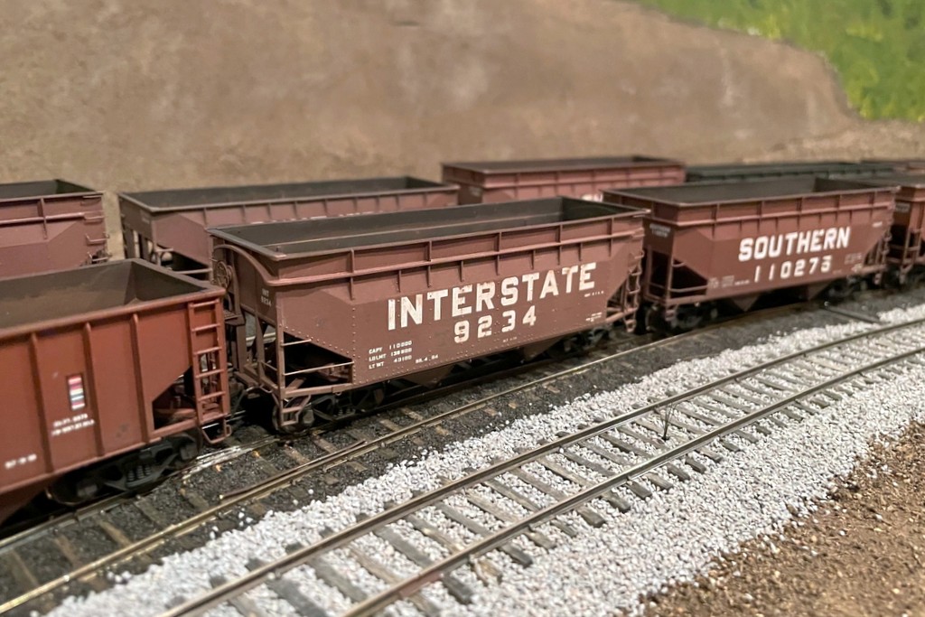
I’ve wanted to build a model of this car ever since I saw it in Ed Wolfe’s first Interstate Railroad book. The Altas offset hopper makes it easy
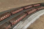
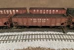
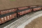
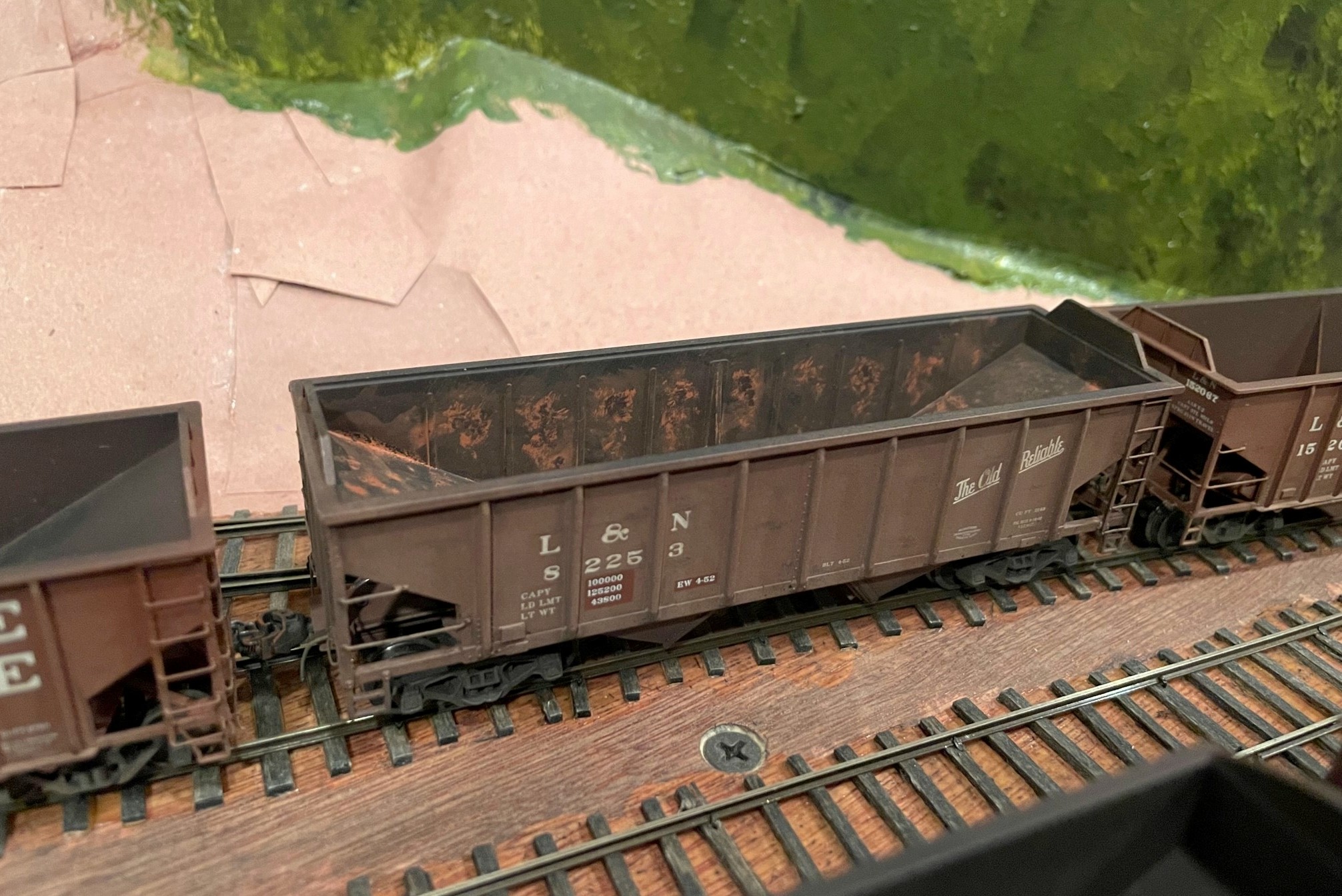
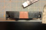
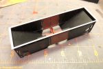
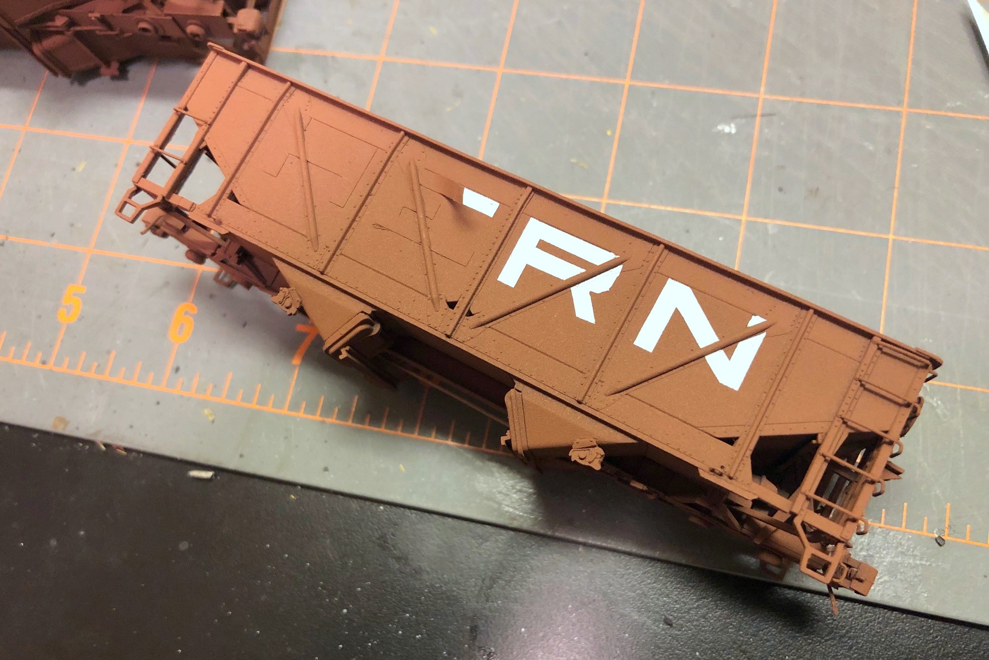
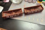
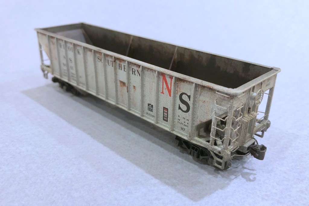
Most of the cars in this class represent old 50-ton cars relegated to “yellow ball” captive service between local mines and the huge coal transloader at Appalachia, VA where the St Charles Branch joined the Southern mainline. A few cars are regular offsets and war-emergency rebuilds including offset 112773 which spent a lot of time against a 100W lightbulb getting “beat up” to look the part! In addition to the Interstate car, there are four other cars with scratchbuilt height extensions including three offsets and a war-emergency rebuild, representing cars which received their height extensions in the mid-to-late ’70s.
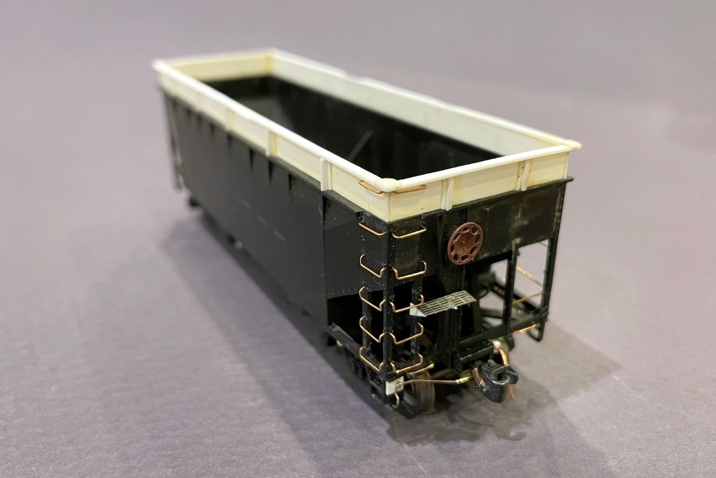
Athearn 34′ offset hopper with an 18″ extension made from sheet and T-shape styrene
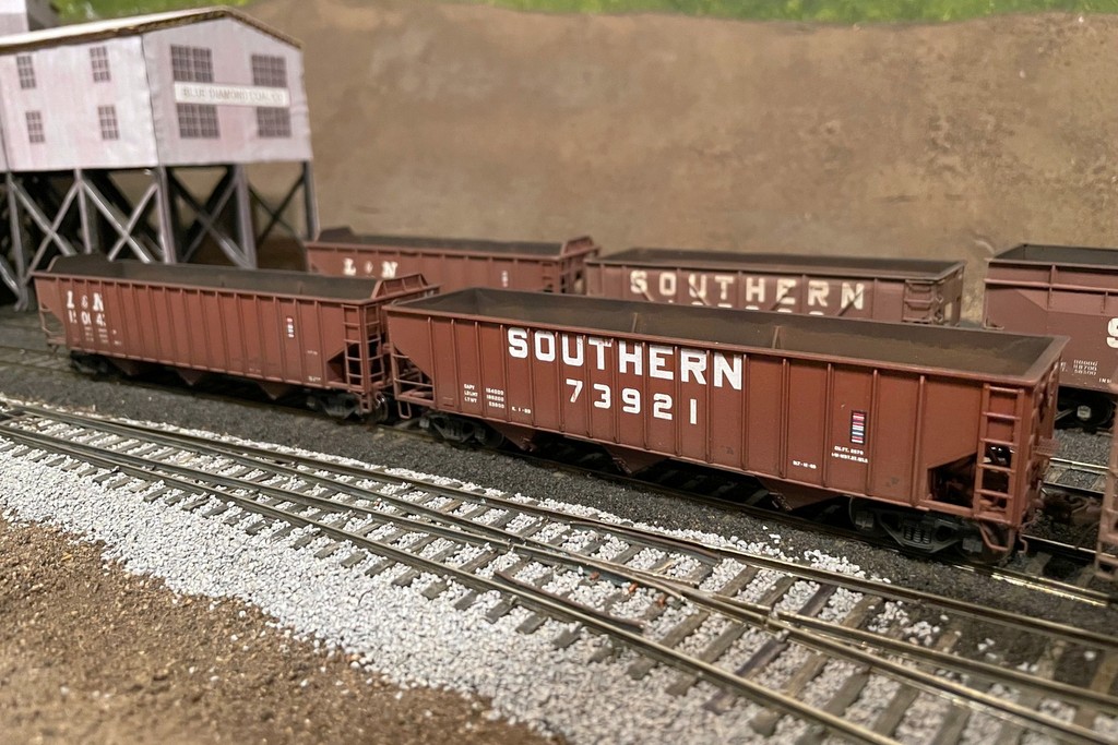
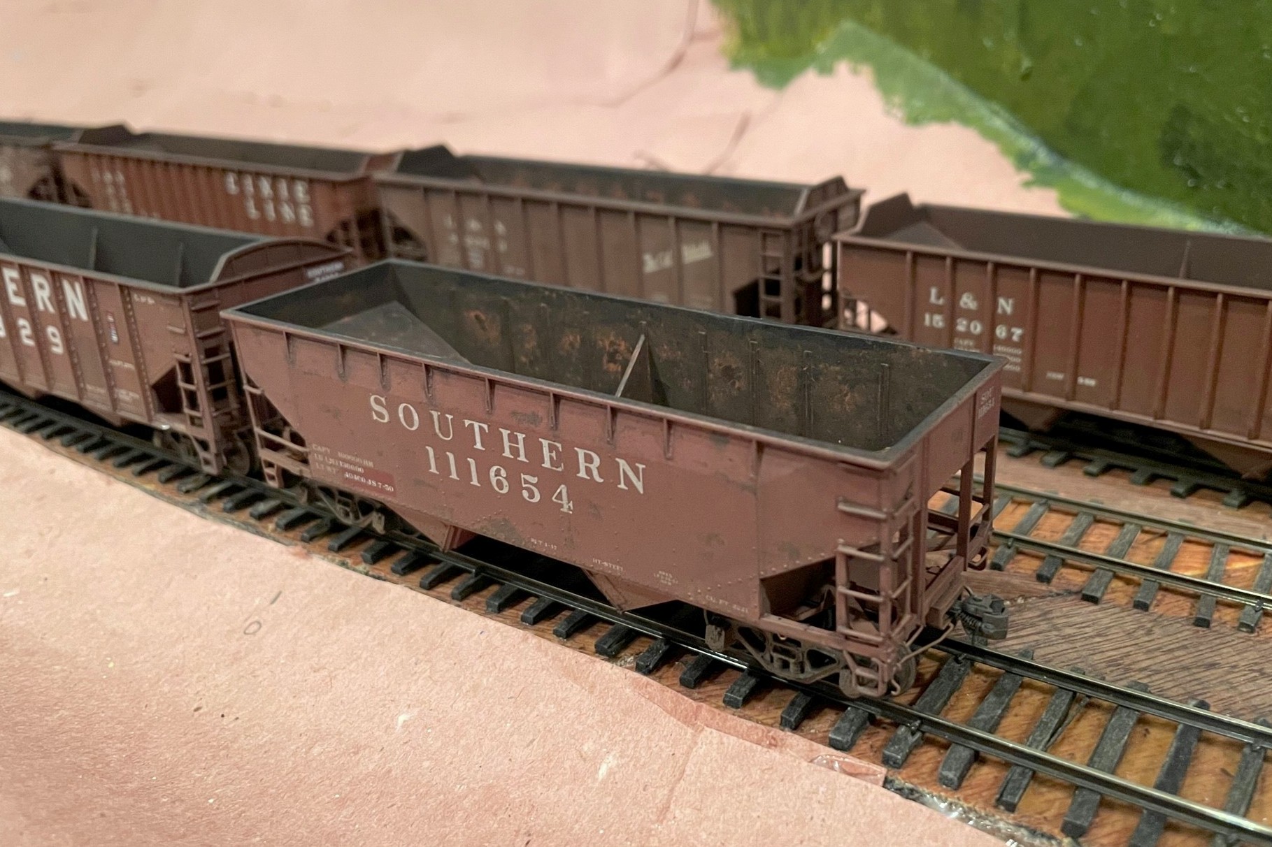
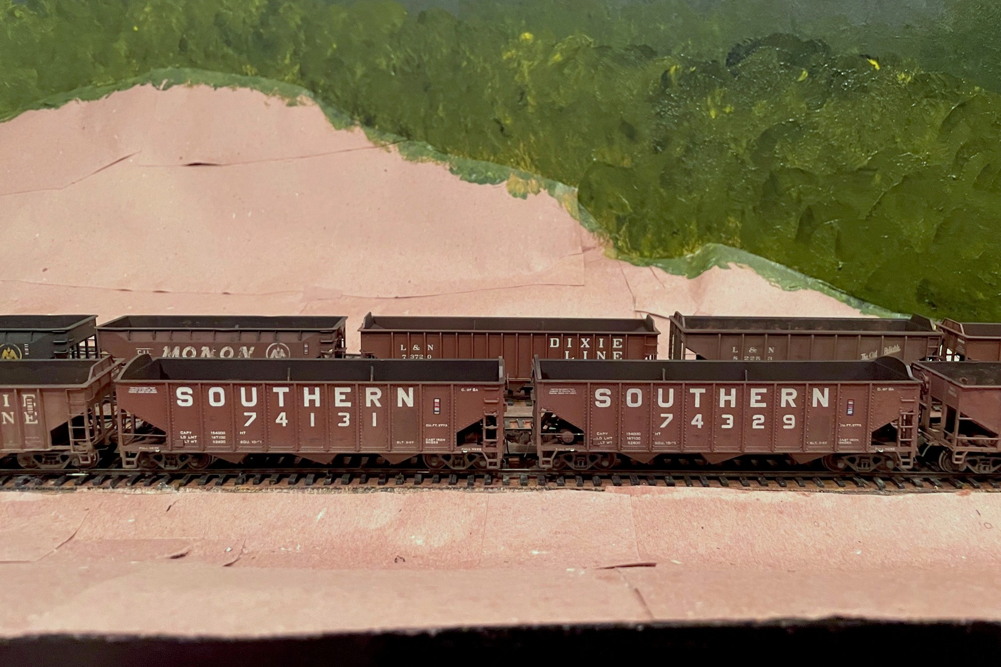
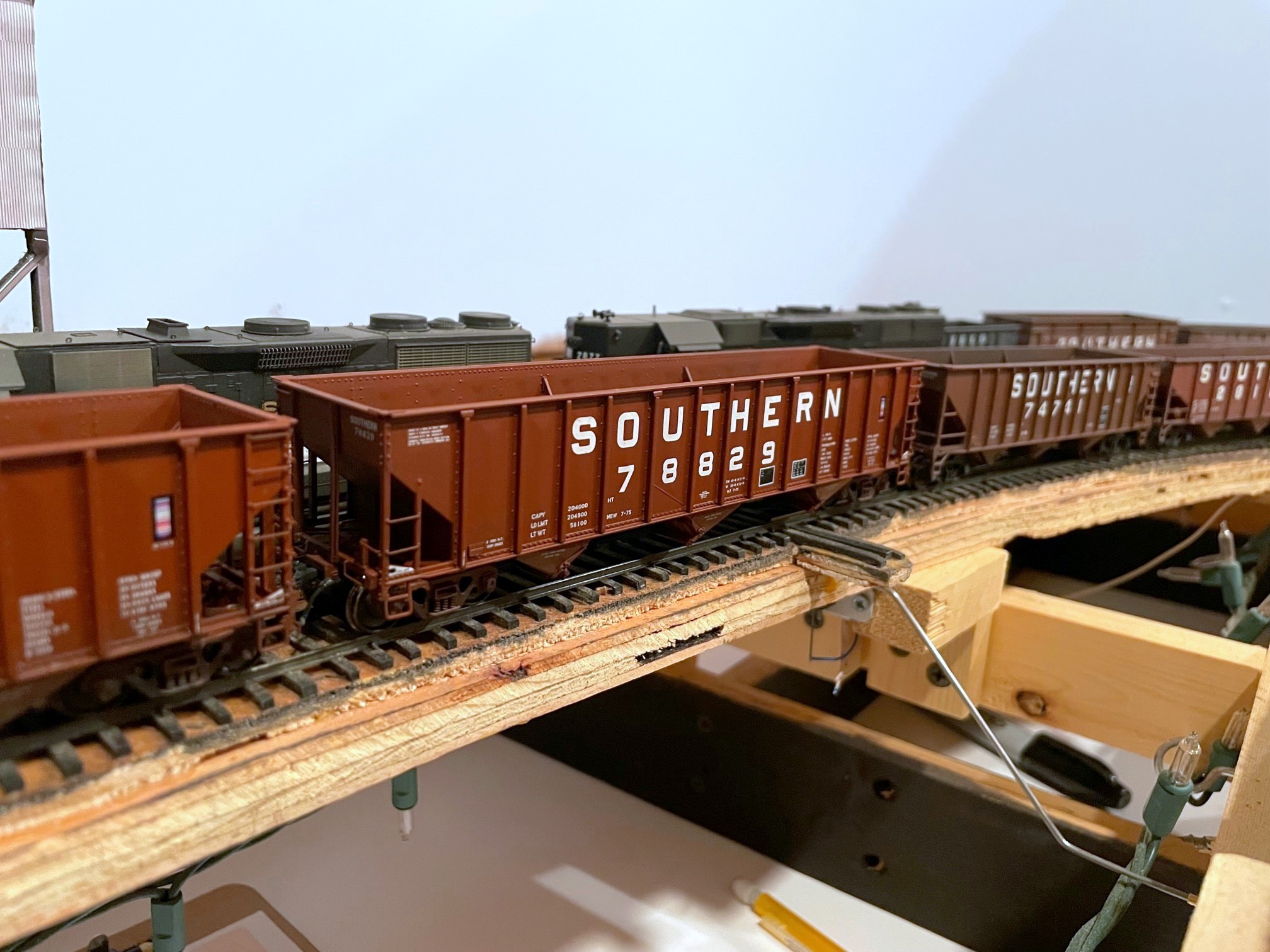
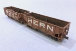
The class includes a couple unique Southern 70T cars as well. The first is a “standard” hopper from the large 70300-73749 class in its original black paint scheme. The first 3,000 or so cars were delivered in black and made it into the mid-’60s before being repainted. Another hopper, 73921, is a Pullman Standard PS3 70T hopper clone that’s been repainted in the more modern Southern scheme from its Railroad Roman scheme. This car, along with the L&N PS3 70T hopper in this set, were kitbashed from Atlas 70T 9-panel hoppers, one by me and one by Patrick Tillery. These were built before the Tangent model was released and have been sitting on the shelf for years–I’m happy to finally have them on the layout! Rounding out the class is an L&N PS3 50T hopper from an old Train Miniatures / Walthers kit representing a repainted car from the late ’60s.
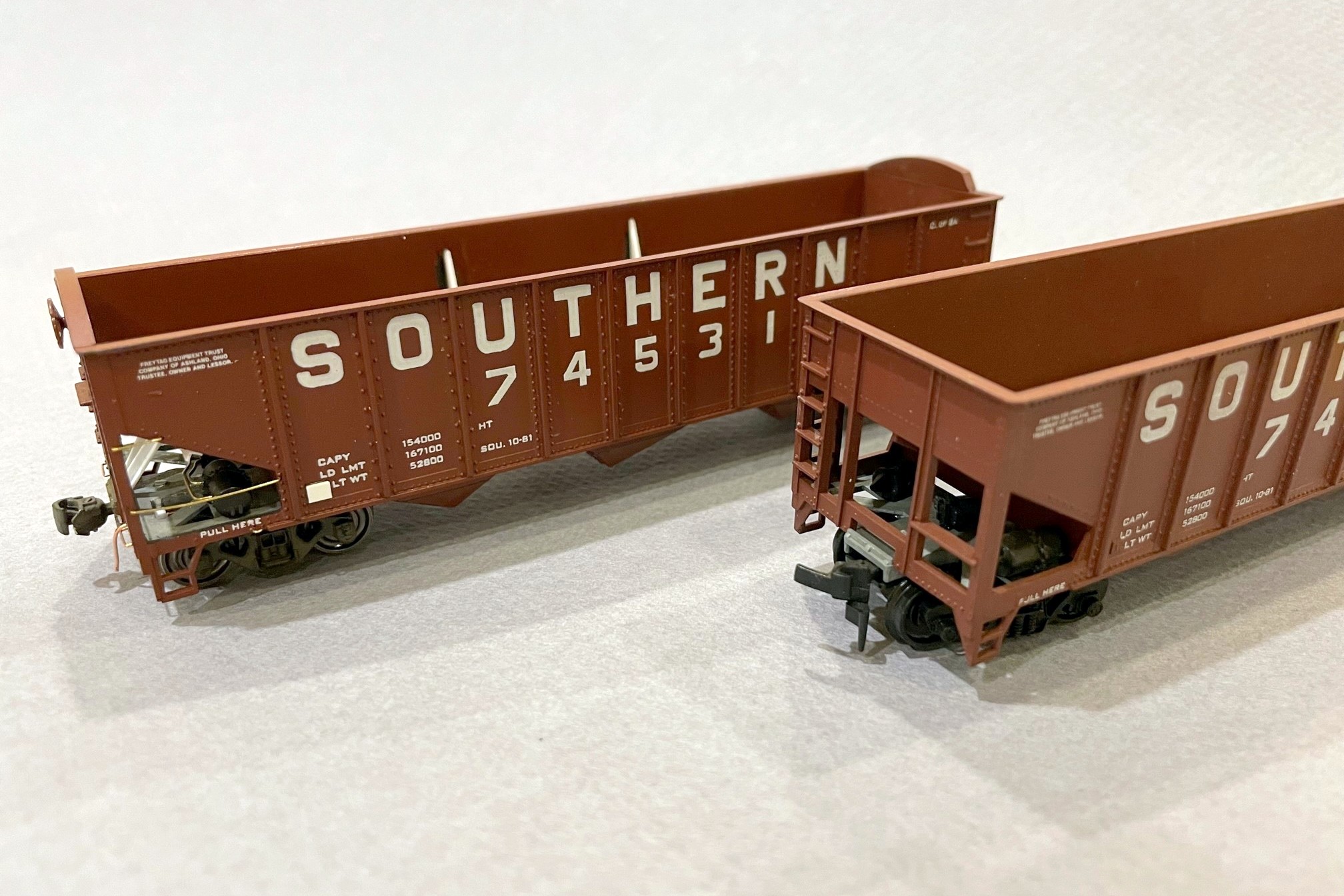
A Southern PS3 clone and L&N PS3, both kitbashed from Atlas 9-panel 70T hoppers
The red cars were painted with either Tamiya NATO brown or a mix of Tamiya NATO brown and flat red–this mix will probably be my standard in the future, and I intend to vary the mixture to get variety in future cars. Never in my life have I done this many decals in one stretch. All told, there are more than 600 individual decals on these cars! Most of them are from K4 decals with a few Mask Island sets. The L&N hoppers are from a Great Decals set and a Curt Fortenberry set I got many years ago. Some Microscale small lettering and ACI labels rounded things out. Most received pretty heavy weathering since most represent non-interchange cars in their last years of service. I’m happy with how these cars turned out, and I’m happy I’ve got 9 more “yellow ball” hoppers to augment the fleet that’s been needing some help for a while.
All 12 hoppers from the “class of Jan 24” including 9 Atlas 70T, 1 Atlas 50T offset, and 2 Proto 50T war emergency rebuilds
I’m proud to introduce you to the hopper class of January 2024. This class is comprised wholly of “run of the mill” hoppers for the layout rather than any super-detailing projects. Most are Atlas hoppers including 9 70T 9-panel hoppers and a single 50T offset. Rounding out the class are two Proto 2000 war emergency rebuilds. All hoppers are factory painted, but most have been renumbered, and some have had their round “O” replaced with the rectangular one more appropriate for my era. Renumbering/relettering consisted of carefully scraping off the unwanted digits with an X-Acto chisel blade and adding new decals. I used a tiny paintbrush on the ends to paint in something close enough to the right number to not stand out from a distance.
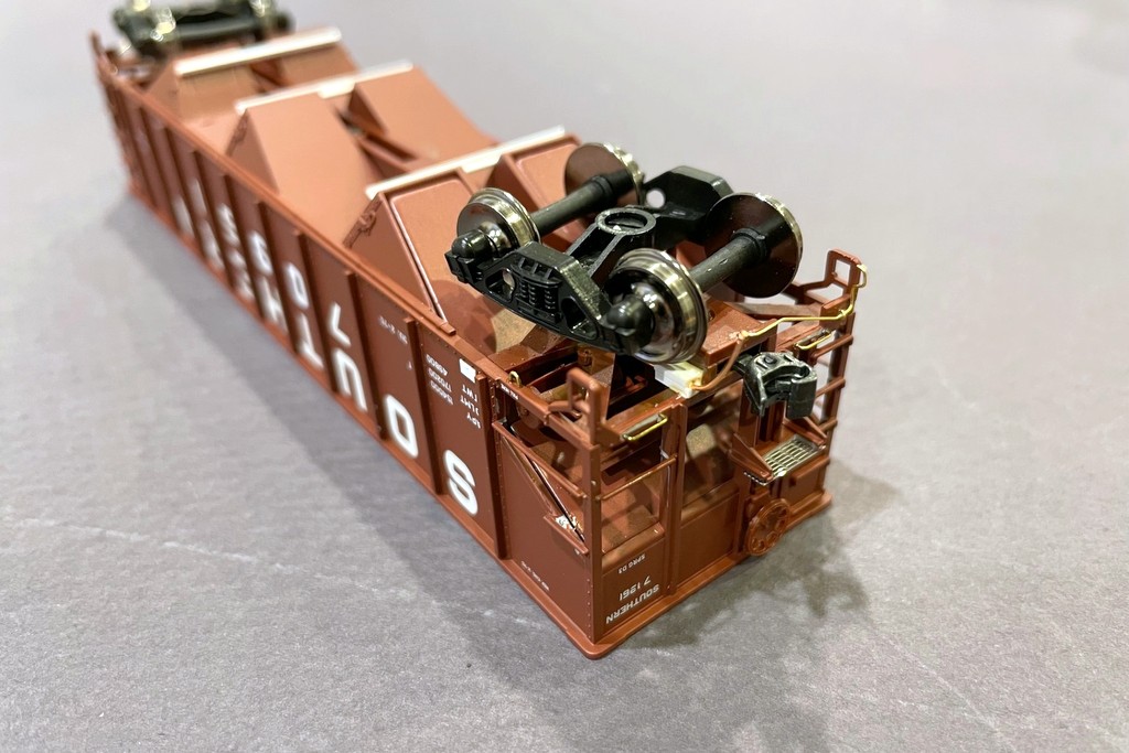
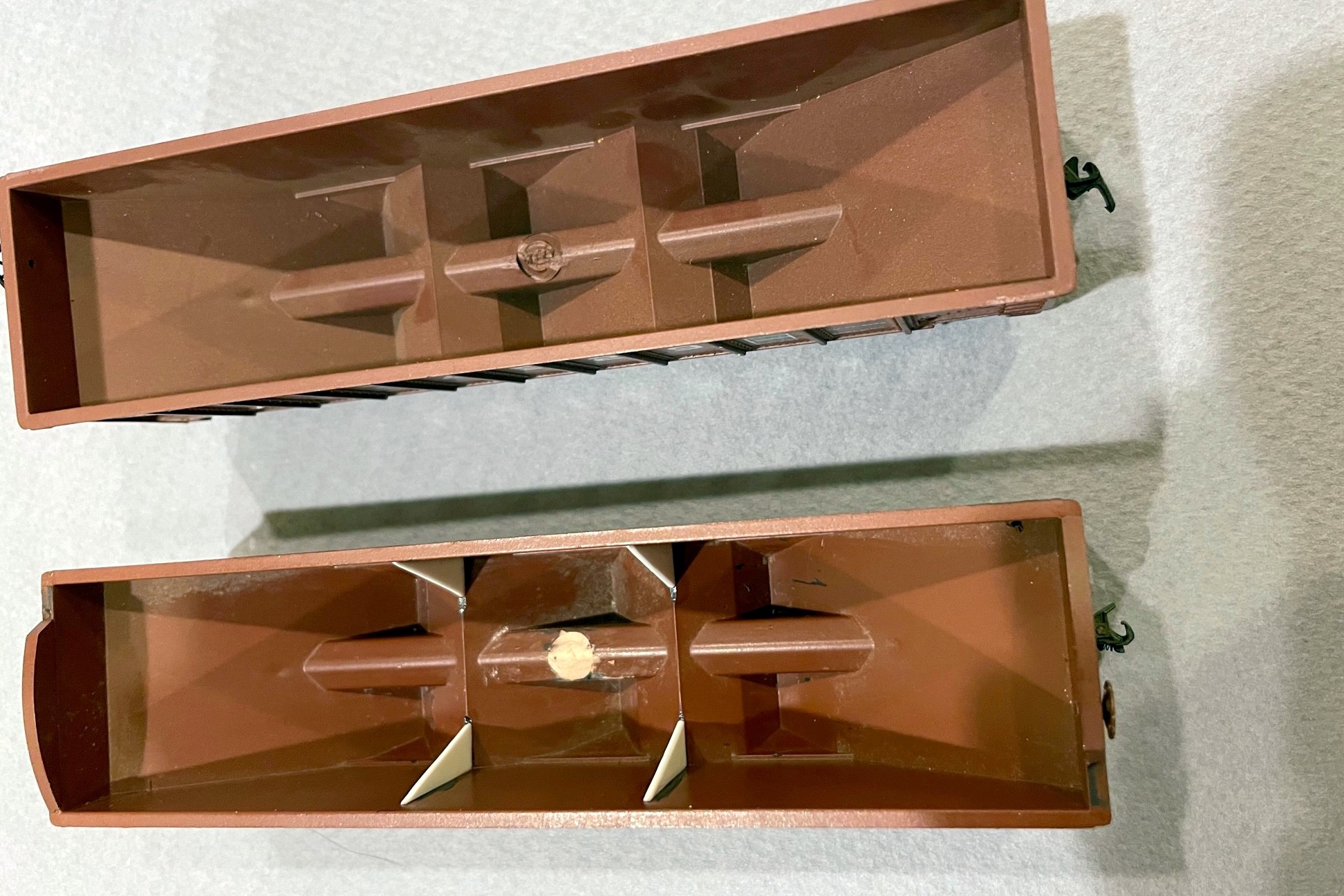
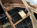
The underside of an Atlas hopper shows the additional details including door bars, train line, grabs, brake platform, and coupler cut bar
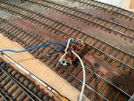
The Atlas cars all went through a series of “upgrades” including shaving the backs of the grabs to make them more round and closer to prototypical thickness–this is far easier than replacing all the grabs with wire, and from 12″ away, you really don’t notice that a few of the grabs are still molded onto the body. I did replace all the grabs adjacent to the coupler with wire grabs, and I added homemade coupler cut bars from .012″ brass wire and train lines out of copper from old Cat 5 ethernet cables. Each car also got tack boards made from strip styrene. Since I first posted about the “layout standard hopper” four years ago, I’ve added a couple more details including an etched metal brake platform cut from a sheet of roof-walk material and the bars across adjoining doors, made from styrene channel. The Central of Georgia car also got some slope sheet braces made from styrene L shape. I touched up the metal and bare plastic with some black and Vallejo “hull red”–not an exact match, but close enough once the weathering goes on. I used a silver Sharpie to add a little detail to the elbow and ends of the train lines.
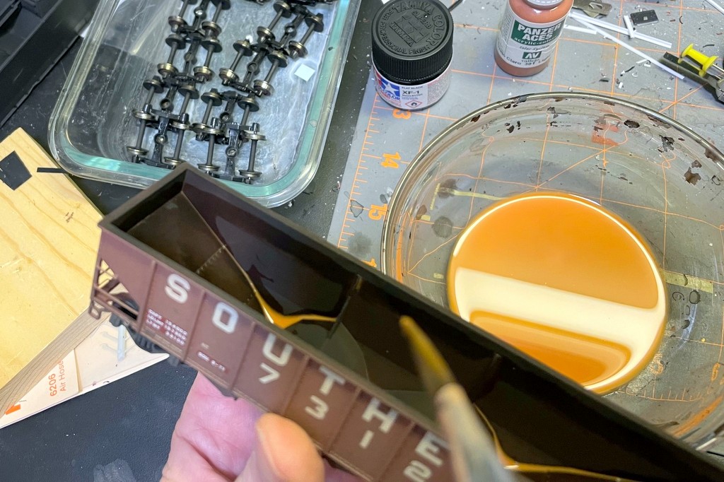
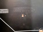
The interior rust is a couple layers of rust-colored wash
I had a lot of fun weathering these. Each first got a coat of matte lacquer spray to help blend in the decals and to give the cars a nice finish for the weathering to stick to. Next, I dry brushed some black, light rust, and dark rust onto the sides of the older black cars to simulate fading paint, scrapes, and rust patches. Some of the red cars also got a few nicks of dark rust. I masked off the capacity data and shop dates of a couple of the cars to keep it new looking like a patch job. I airbrushed all the cars with a light coat of dark tan on the sides and underframe and some flat black inside the hopper. I sprayed the black thinly letting the red still show through a bit. The undersides got a little black as well to add to the grime. Next I gave each a wash or two of flat black to bring out some of the detail and add some grunge. The last step was the hopper interior rust. I made a wash of light rust color, painted a “water line” just below the top chord where the coal would reach, and filled in everything below with the wash. I sopped up any excess with a paper towel. Each car got 2-4 coats leaving some more rusty than others. A few of the older cars (like the black ones) got some extra dabbing of light rust on the insides and a little dry brushed dark rust for some variety.
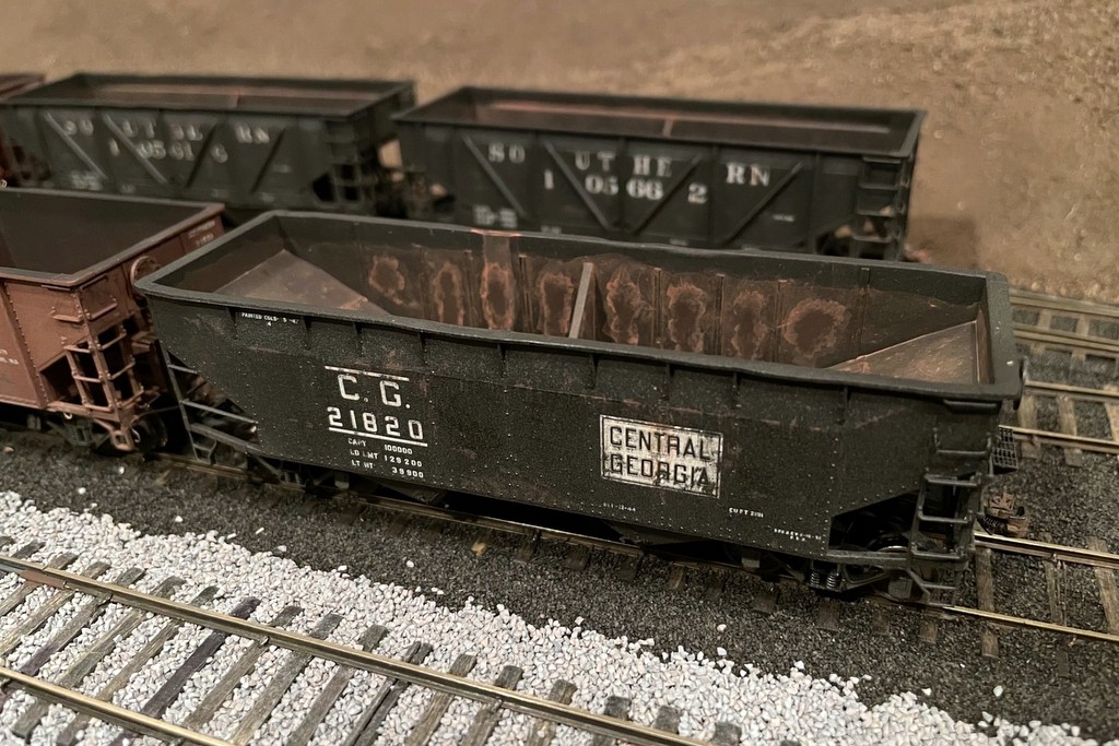
The CofGa hopper got the most weathering of the bunch
Overall I’m happy with how these turned out, and I like this technique for weathering the inside of older hoppers. While newer hoppers tend to have lighter rust or even bare shiny metal, an older steel hopper tends to settle into a mottled dark rust color which I think the repeated light rust washes over flat black airbrushing accomplish pretty simply and convincingly.
Here’s an Atlas hopper before touch-up painting and weathering showing the additional details and “grab shaving”
The hoppers all got medium weathering and old rusty interiors suitable for their represented age
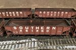
70T hoper 281260, assigned to the CNO&TP, shows off its dark rusty interior
The only 70T hopper in older roman lettering is 281056–renumbered to fit into a CNO&TP series of these cars
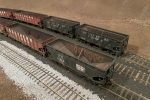
The “oldest” hoppers in the group are a pair of war emergency rebuilds still in original black and a “heritage hopper” Central of Georgia hopper in original colors
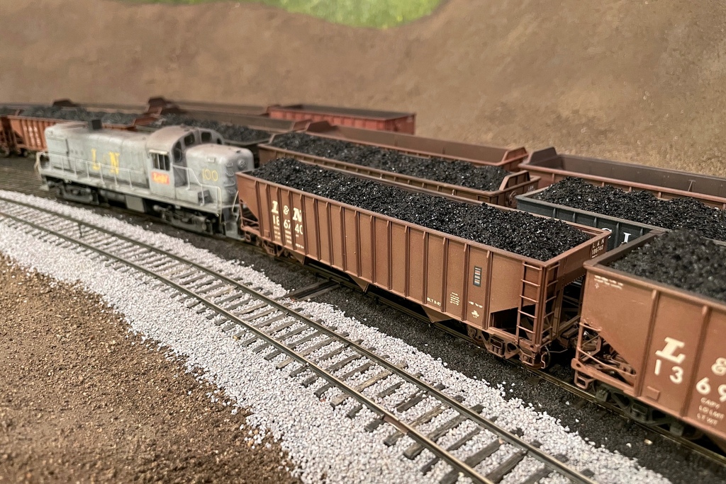
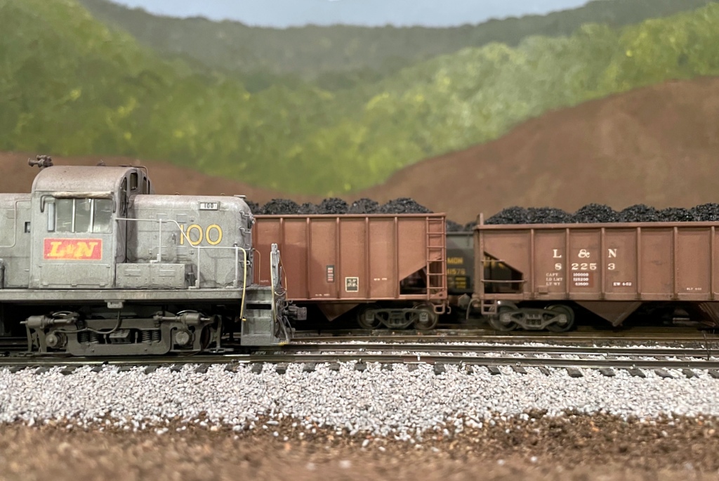
A few of the cars with some coal loads showing the heaps straight from the tipple
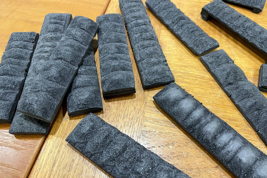
Here are several of the finished coal loads waiting to head back to the L&N
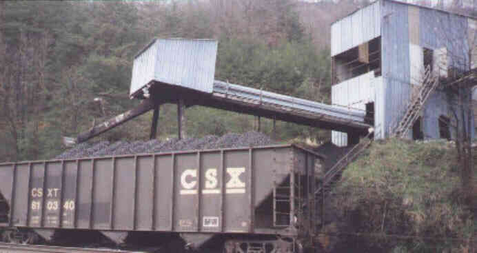
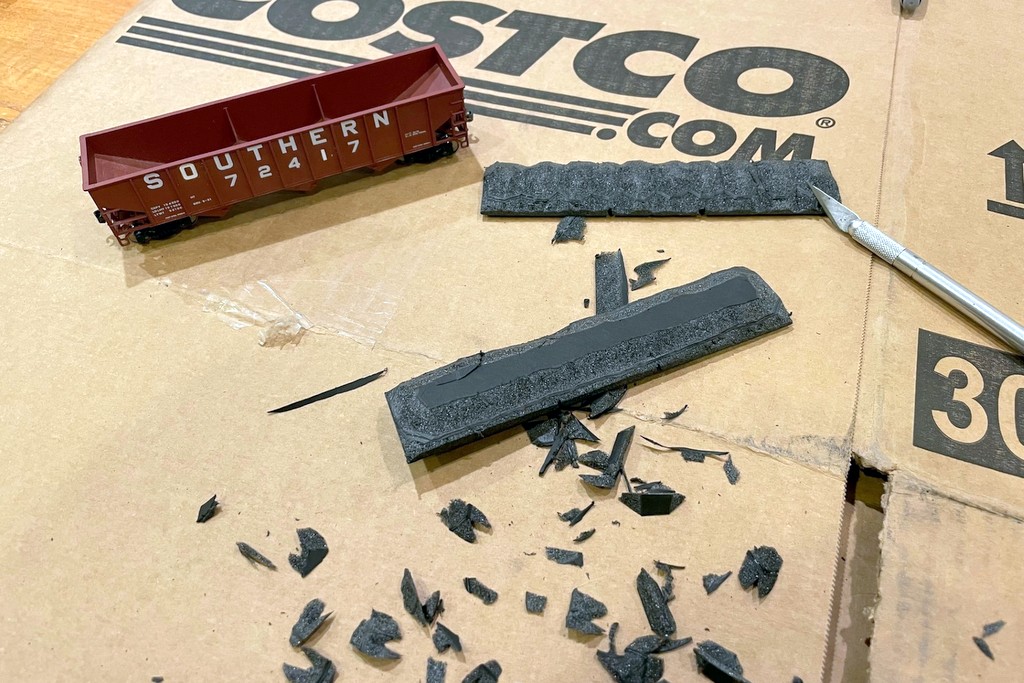
After years of hauling around black foam core inserts pretending to be coal loads, I finally got around to finishing some of them… 58 to be precise! I won’t go over the whole process here (article coming soon on Appalachian Railroad Modeling), but I’ll give you the basics here. Most people are used to seeing gently sloping coal loads that can barely be seen over the top of the car–this is a load that’s been on the road for a while and settled into the car. I model coal at the source, and this looks very different. In the ’60s and ’70s, much of the coal was loaded by feeding a car under a chute a few feet at a time using gravity or a winch to pull the car along in stages. This resulted in a series of high, distinct, and often uneven coal lumps, perhaps a dozen or more.
This hopper shows off the distinctive lumps of freshly loaded coal from a tipple that moves the car a little at a time. Triangle Dock, Elkhorn City, Bob Helm photo
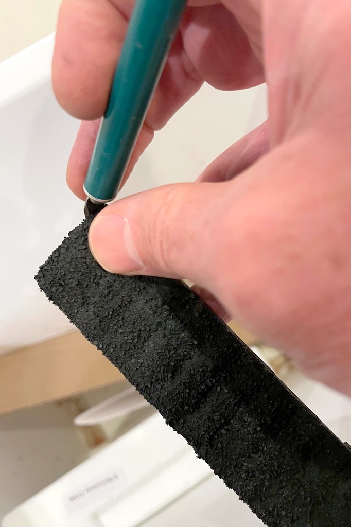
I haven’t seen too many modelers attempt this look, so years ago (like 25 years ago), I came up with a way to model this look using foam core and real coal. 25 years later, the biggest improvement has been the introduction of black foam core which does a MUCH better job of hiding any imperfections. I use 1/2″ black foam core, though some of the older forms were made from two 1/4″ pieces laminated with white glue. I basically cut them about 1/16″ smaller than the dimensions of the hopper, press them into the car to know where to cut notches for any bracing, and carve the load. I start by cutting a rough 45-degree angle around all sides, then I cut notches where I want the lumps to be. I try not to be too precise, and all the lumps are slightly different sizes. I then start rounding the lumps and eventually cut the top poster board layer off the foam core. The final shaping is done by compressing some of the foam with my fingers to smooth it out. If it needs it, I’ll add little pieces on the ends underneath and cut them to fit the car so the load sits a little higher.
The loads start with 1/2″ black foam core cut slightly smaller than the hopper and carved with an X-Acto bladeSeveral load forms ready for coal–each one is unique
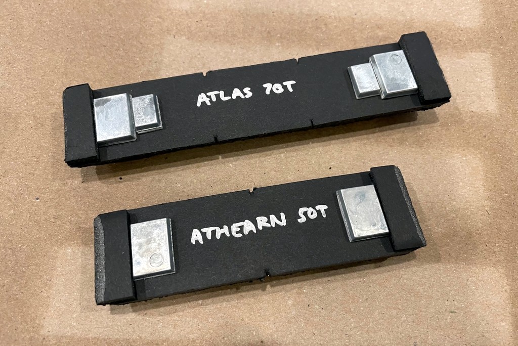
Before I lose track, I label each load for the type of car it fits (easy with a silver Sharpie), and I add a couple of stick-on weights under each load (pinewood derby weights). I want my coal cars to “feel” heavier to a locomotive when they’re loaded, and I also want them to be a little top heavy like the prototype so crews will handle them a little differently.
Once it’s cut to shape, I label each load and I add some stick on weights. This picture also shows the notches carved in for the braces
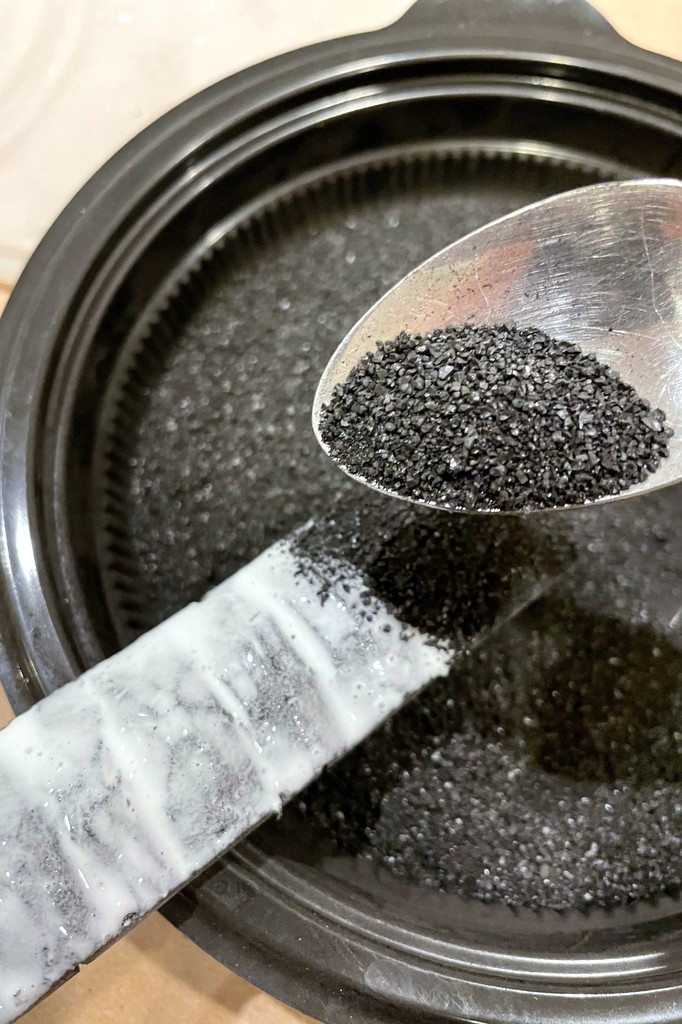
I grind my coal the old fashioned way: with the butt of a butter knife in an old Cool Whip container. Then I sift it with a kitchen strainer to get a container of small coal. I paint the top of the foam core with straight white glue, then sprinkle the coal over the top and shake off any excess. I do this over the coal container so I can recycle any coal that falls off.
The coal is real coal, ground up with the butt of a butter knife and sifted with a sieve before being added on top of a coat of straight white glue
I set the loads on parchment paper to dry overnight. The next day, I spray the tops of the loads with “wet glue” (about 8:1 water:glue + a couple drops of dishwashing soap) until they’re saturated. This really sets the loads and keeps the coal from leaving dust on hands and models. Once the glue has completely dried, I go along each load with my fingers, knocking off any protruding pieces of coal, then I clean up any coal on the edges with an X-Acto blade.
After letting the coal loads dry overnight, I hit them with “wet glue” to further set them and to keep the coal dust from rubbing offOnce the wet glue is dry, I clean them up a little with a finger to knock off any pieces sticking up too high and an X-Acto blade to clean up any coal pieces on the sides
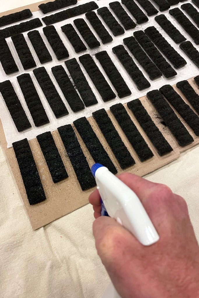
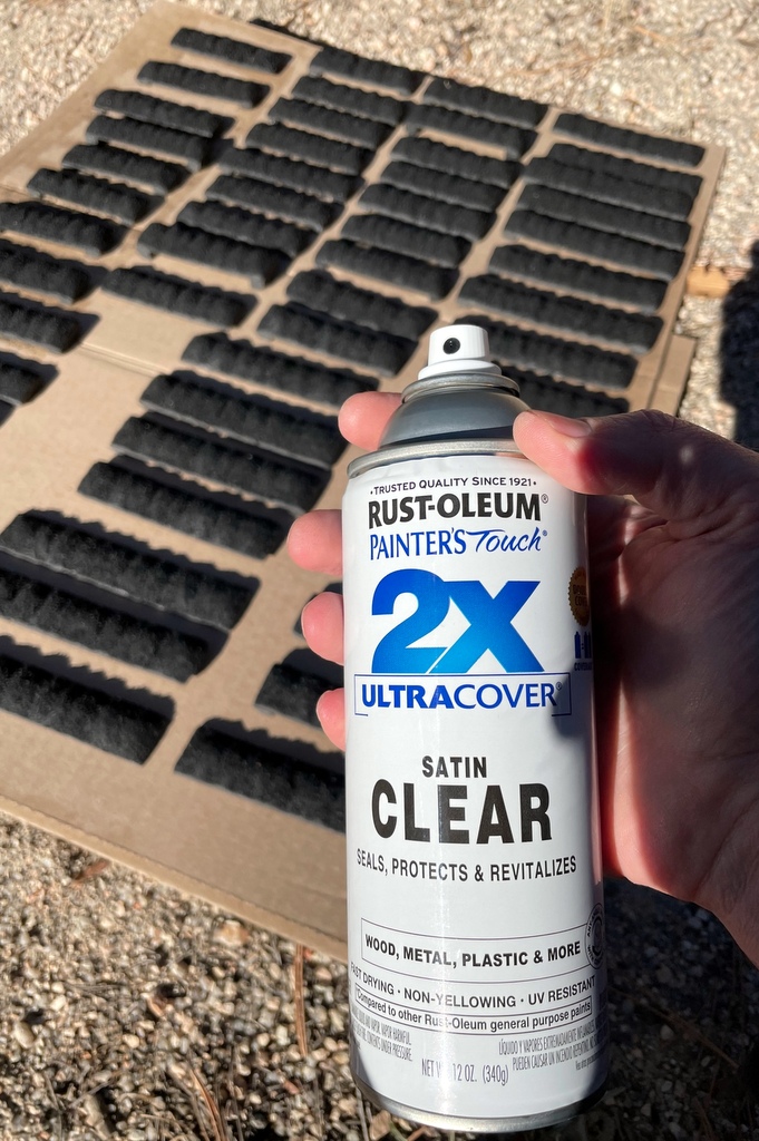
The white glue tends to dull the coal’s sheen, so my last step is to hit the loads with a coat of clear satin-finish lacquer spray–this looks about right to my eye to bring the coal back to its original luster. All told, when you do them in bulk, it only takes a few minutes and a few cents worth of materials per load, and I love the way they look! I also like that each load is absolutely unique–something tougher to achieve with commercial loads.
The white glue dulls the coal a bit, so the last step is to restore a bit of the sheen with some clear satin finish lacquer sprayThese removable coal loads capture the distinctive lumps of freshly loaded coal piled high
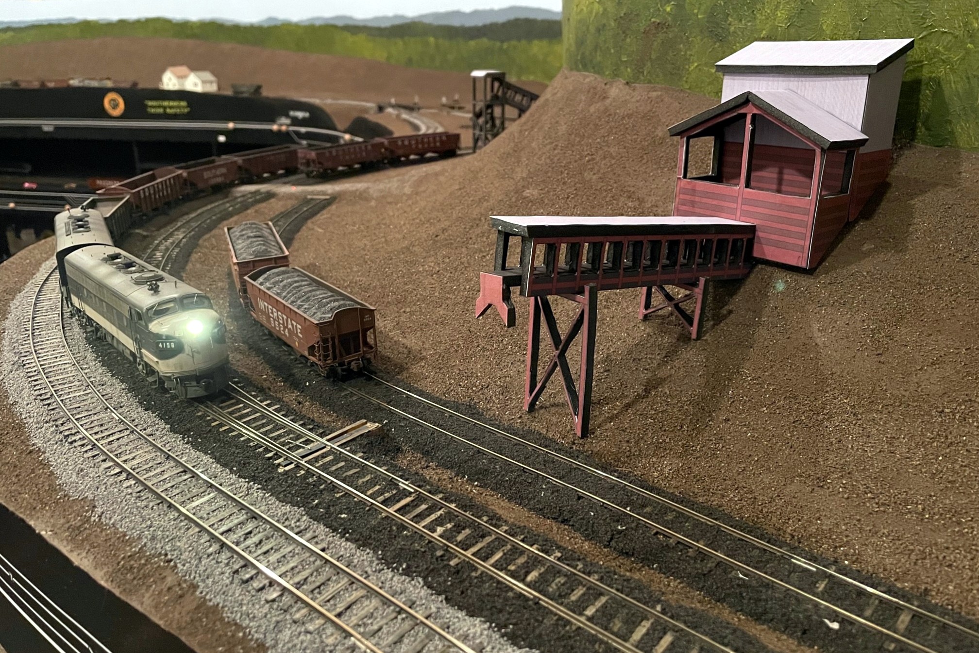
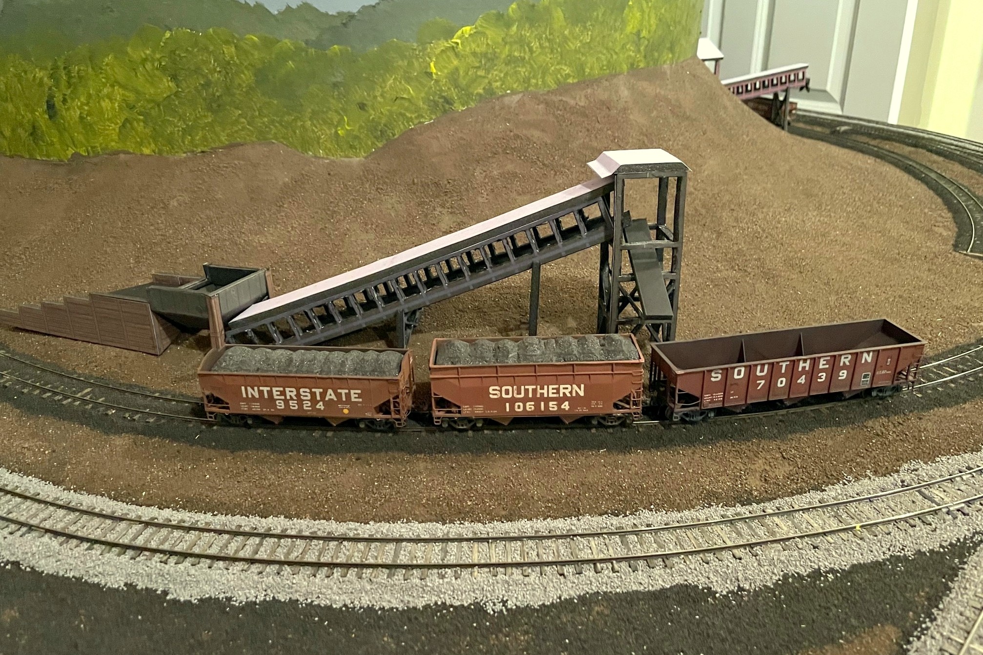
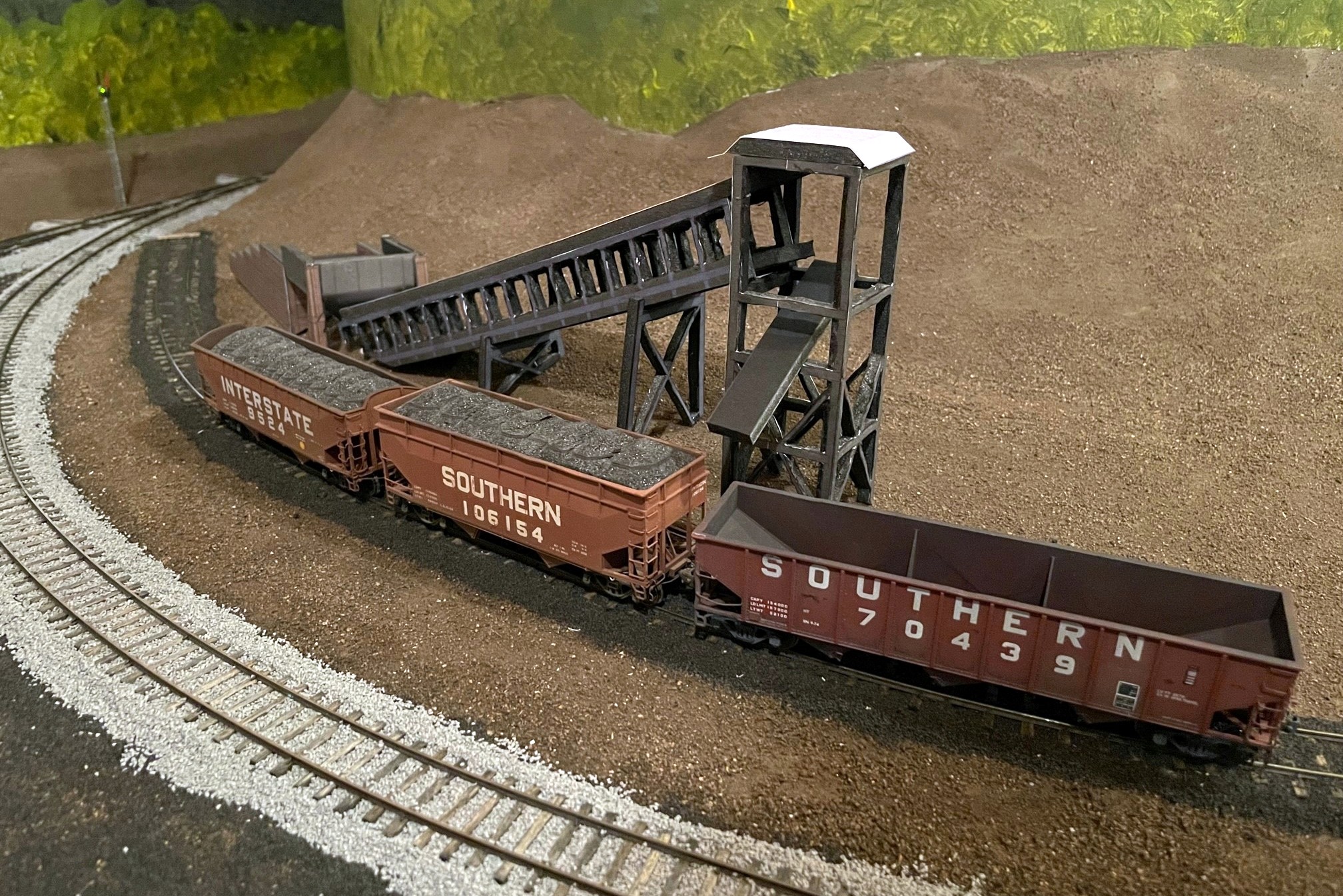
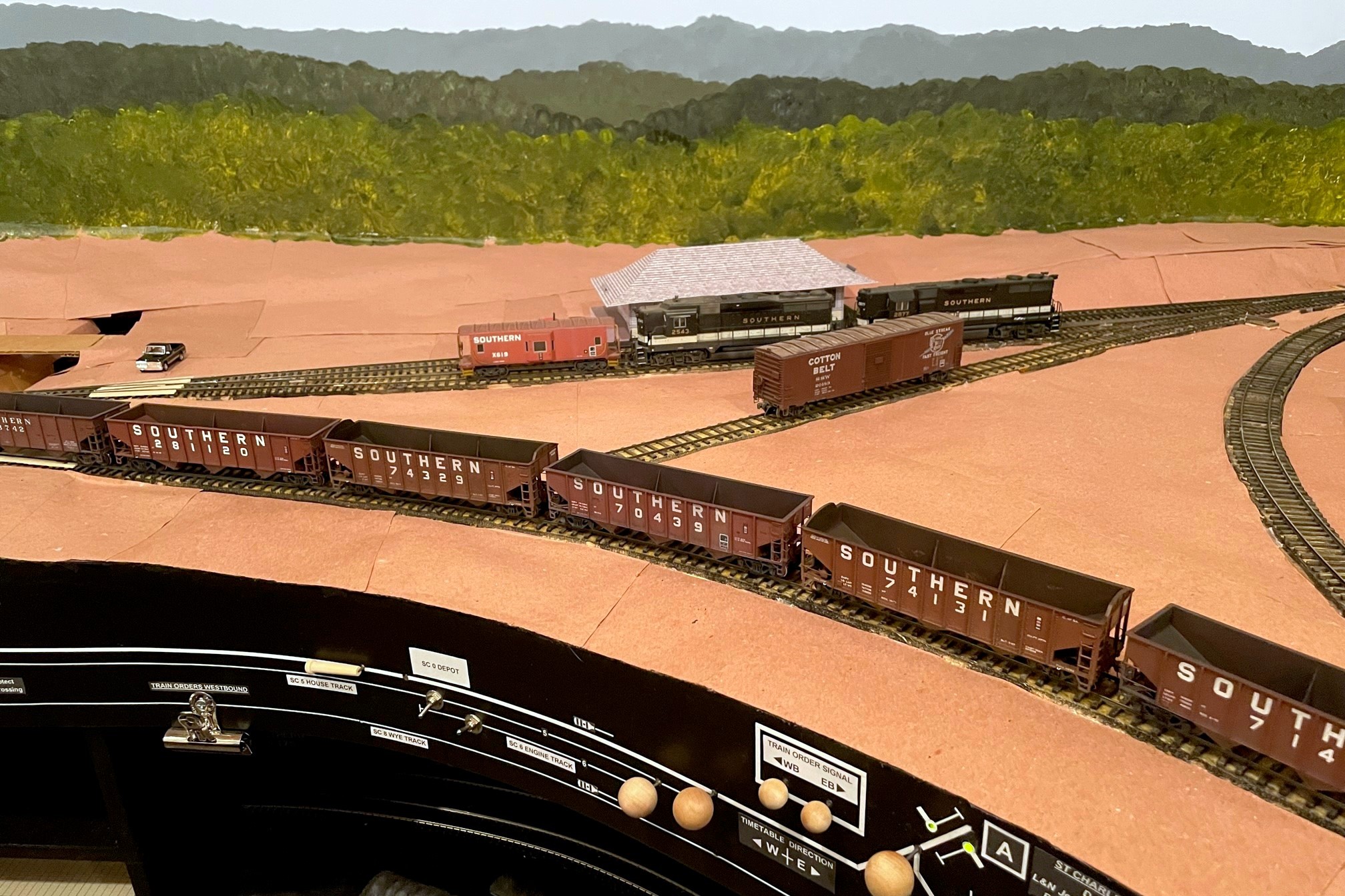
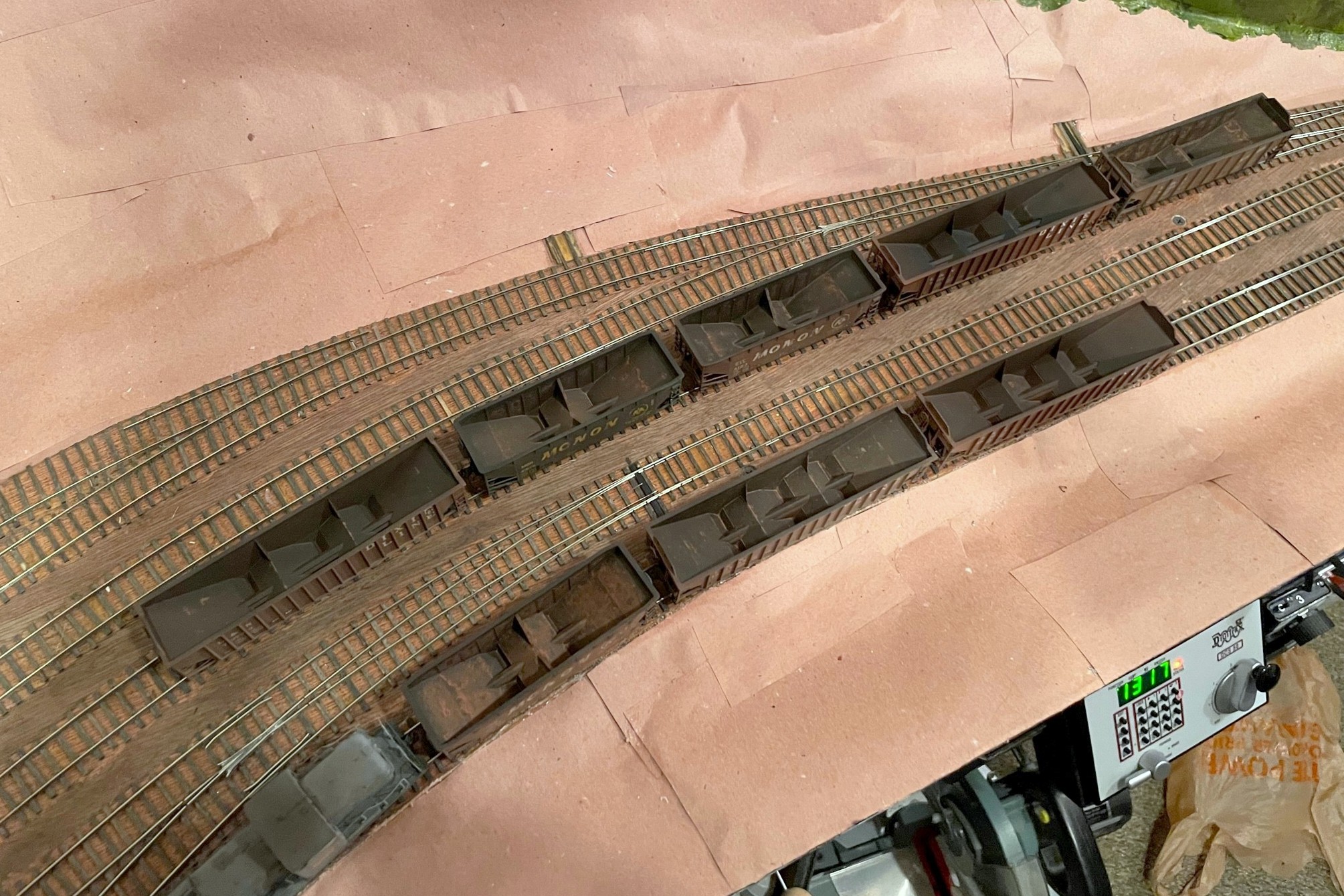
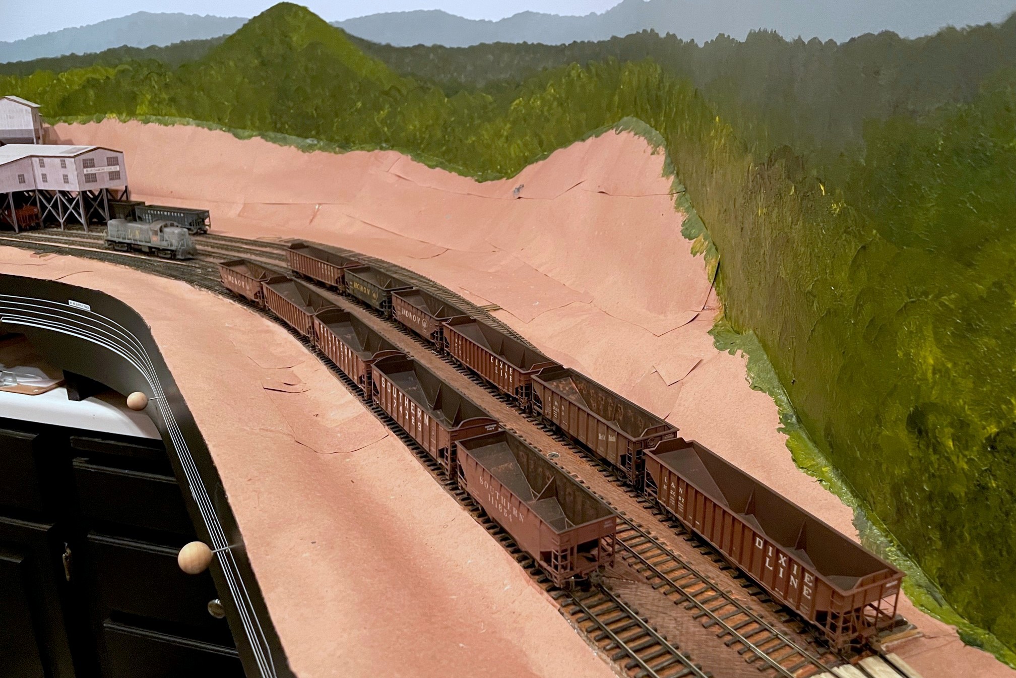
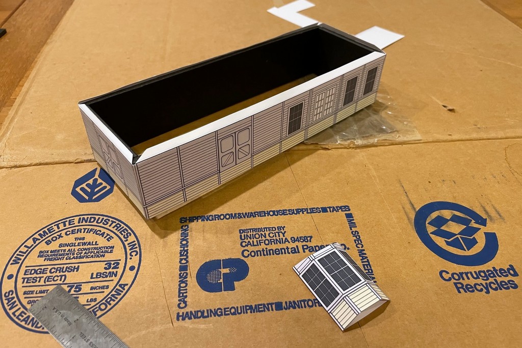
Here’s the full mocked-up scene with the St Charles Switcher preparing to swap empties for loads at the JAD Turner loader–the St Charles loader can be seen just around the hillside
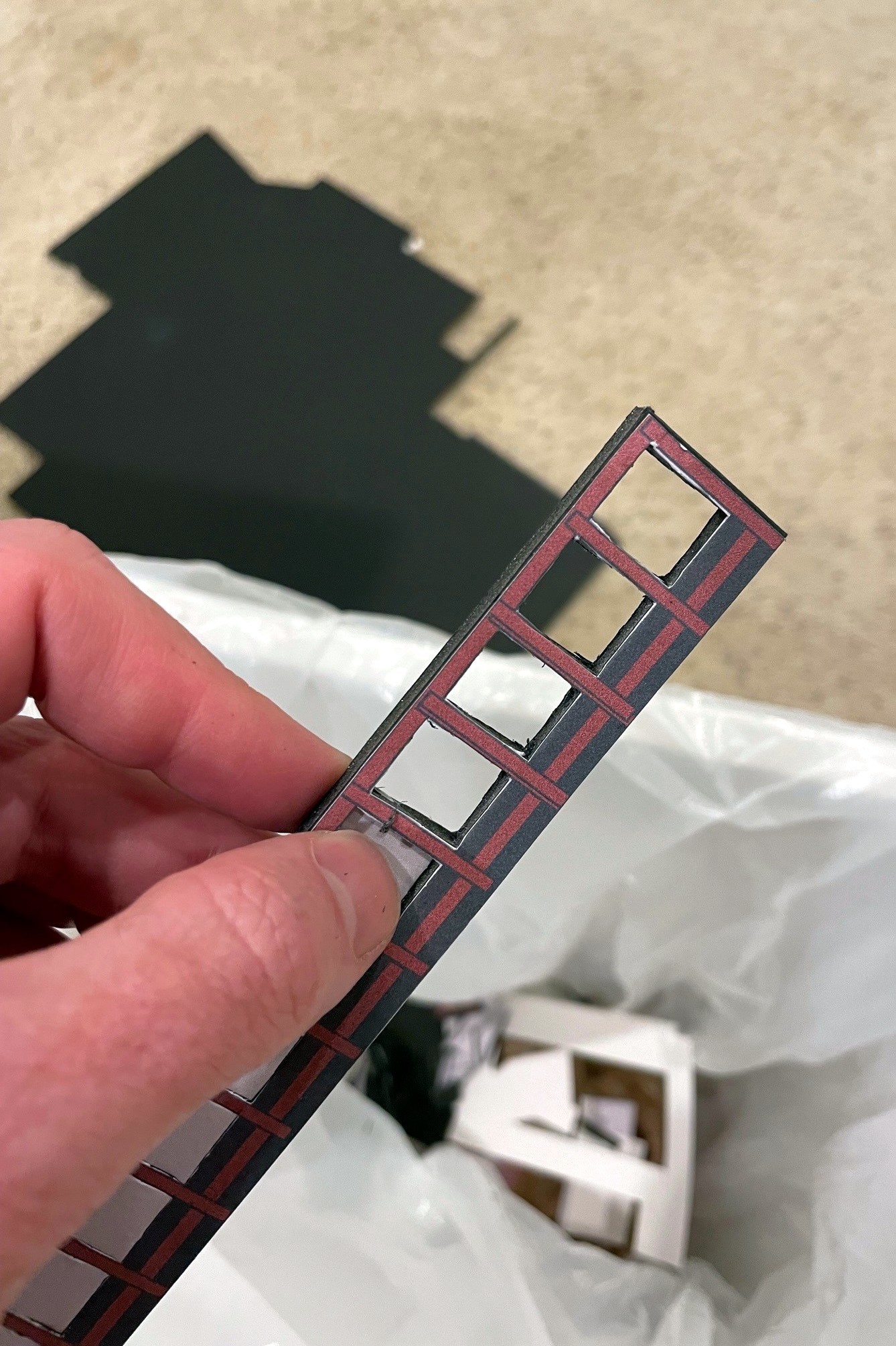
As I’ve discussed previously, I like to build mock-ups out of foam core and paper of the larger structures on the layout that I will eventually scratchbuild. This serves three purposes. First, it gives me an opportunity to create a line-drawing / blueprint and make sure the drawing works before cutting more expensive materials. Second, it allows me to visualize a scene and make adjustments before I build the permanent structure. And third, it gives me a good stand-in on the layout until I can build the real one–something that makes operations a lot more fun than imagining there’s a big structure where you’re switching! For this third reason, I put a little extra effort into the drawings to give them some color and texture. I’ve covered the techniques before, so I won’t repeat them here.
This project involved the two “truck dump” tipples that were built in the late ’70s (as far as I can tell) near St Charles, VA. One is known as JAD Turner, and it’s probably still standing today. The other sat on the wye at St Charles for just a few years–I don’t know it’s name, so I’m just calling it the St Charles loader (super original, I know…). What made this project challenging is I didn’t have any good photos of the loader configuration I needed to model. JAD Turner was modified over the years with a second conveyor and second empty track, but the earliest photo I have of it (a grainy aerial from 1981) clearly shows only a single conveyor. I’m modeling it as if it’s the same tipple but with fewer added parts, so I took the dump shed / crusher section of the current loader along with a single conveyor and came up with this design that looks reasonably close to the aerial.
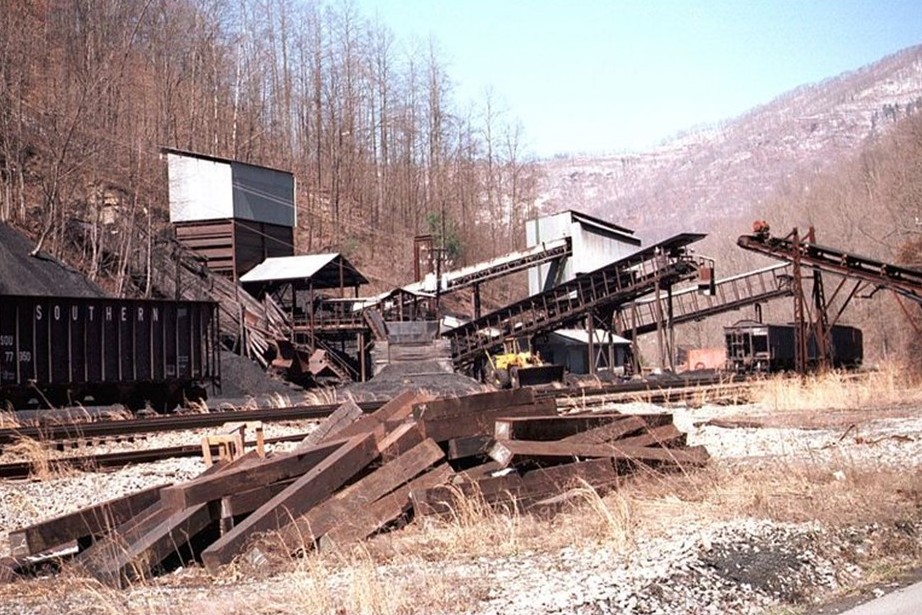
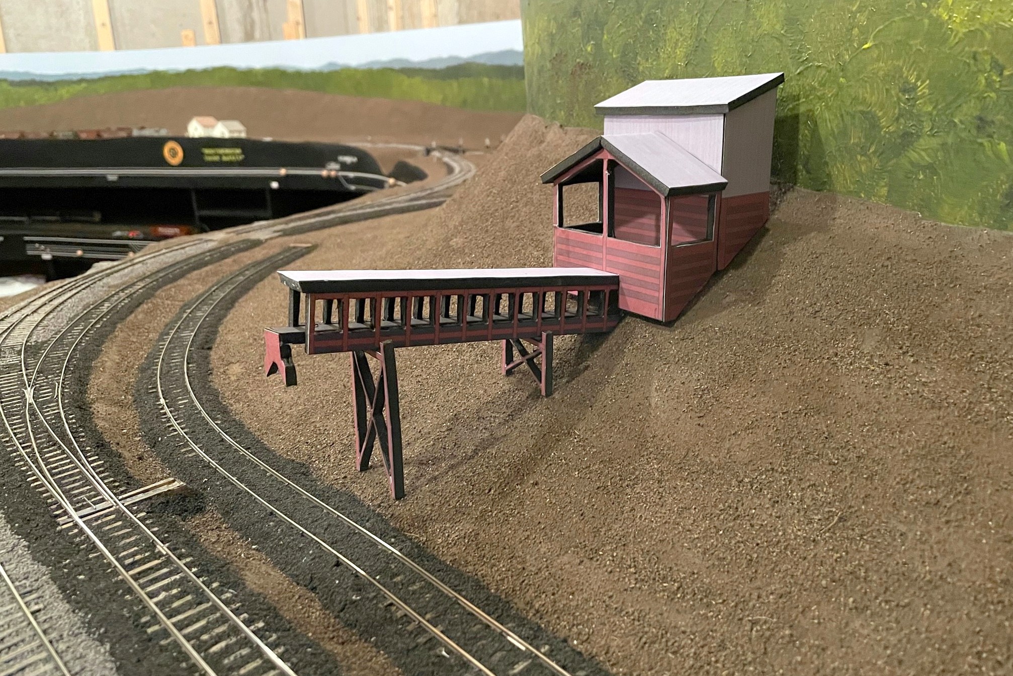
Here’s the JAD Turner loader near St Charles in the late ’90s with additional chutes added, but I modeled the core dump shed, crusher, and one of the conveyors (Robby Vaughn photo)Here’s the finished JAD Turner loader mock-up complete with a little double chute over the rails
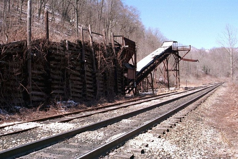
St Charles was a little more challenging as the ONLY photo I have is a grainy aerial from 1981 showing what looks like a pile of coal, a conveyor (maybe two), and what looks like a dump ramp but no shed. I didn’t have to look far to find something close. Just up the road between St Charles and Mayflower was a loader known as “Southwest” which had a similar dump and conveyor arrangement. Southwest was built after my era, so I won’t have to have two similar looking loaders on the layout. Who knows, perhaps they moved the loader from St Charles up to Southwest? That’s my story until someone proves otherwise…
The Southwest loader sat between St Charles and Mayflower but after my era–I’m using it as the prototype for my St Charles loader (Robby Vaughn photo)A view of the St Charles loader mock-up showing the ramp and dump area
Anyway, here are the results, and I’m really liking the scene now. I can’t wait to build the real things! But first the upper deck…
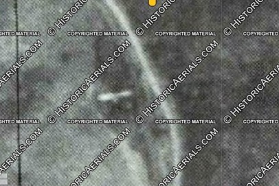
This grainy aerial photo from 1981 (courtesy of the awesome HistoricAerials.com website) clearly shows a single conveyor at the JAD Turner loadout, so I removed “extra” parts from the ’90s loadout to get my design
Here’s the JAD Turner loader near St Charles in the late ’90s with additional chutes added, but I modeled the core dump shed, crusher, and one of the conveyors (Robby Vaughn photo)
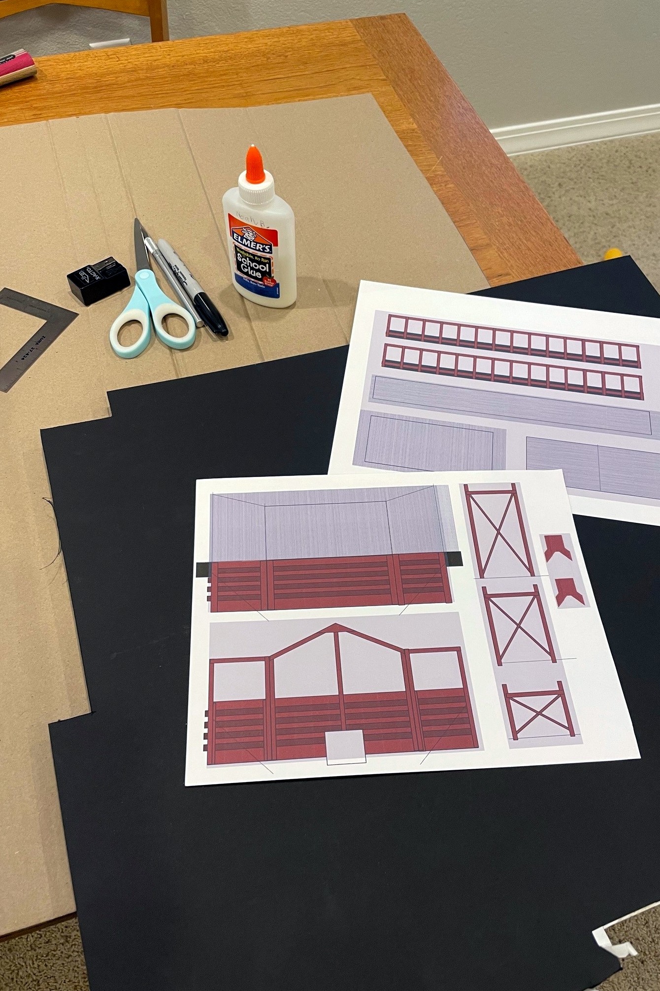
Here’s the drawings I did for a JAD Turner loader mock-up using MS PowerPoint along with the supplies needed to build the “paper doll” mock-up
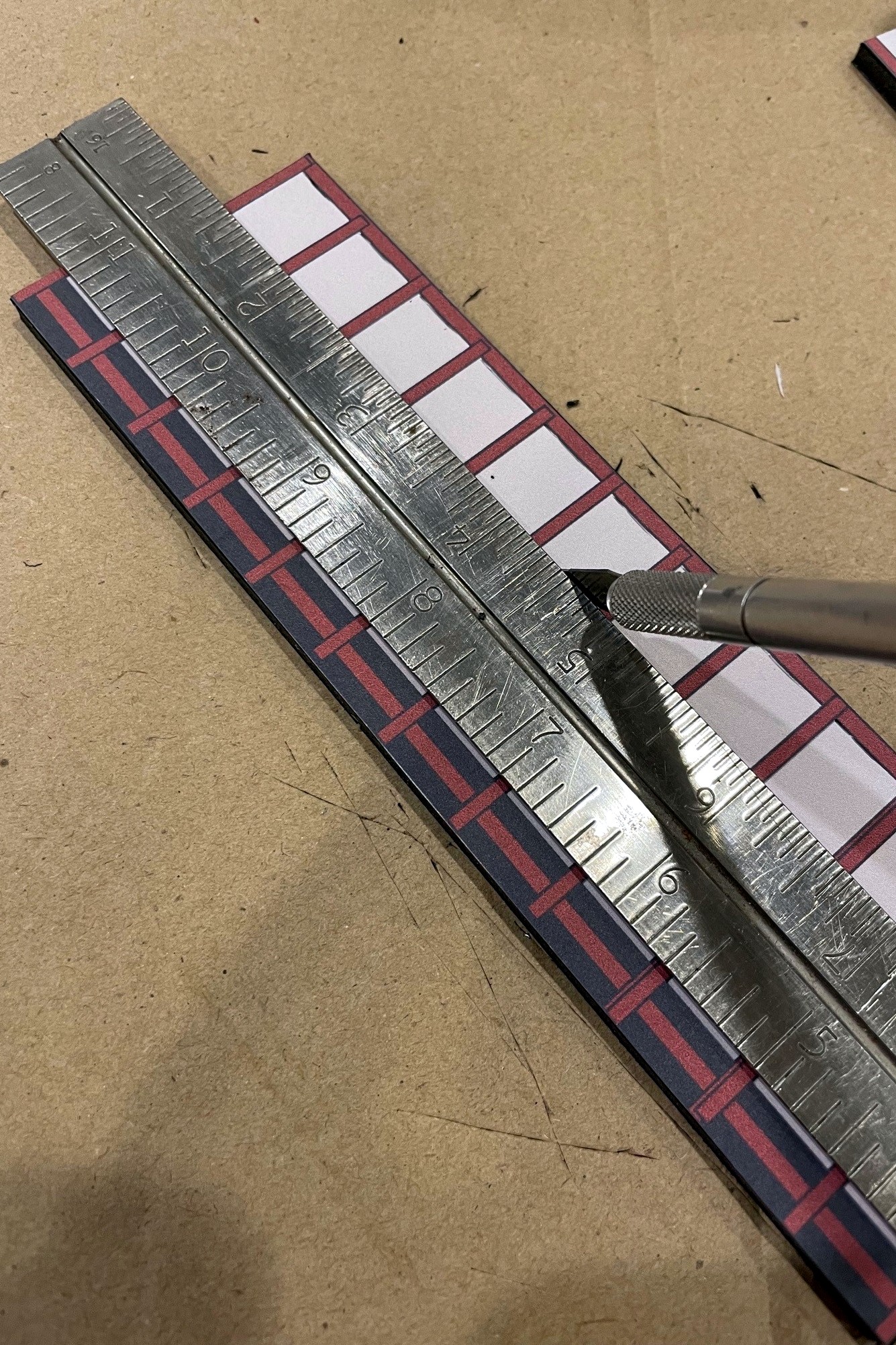
I used a sharp X-Acto blade to cut out the structure details for the conveyors and legs
Once the area has been well scored front and back, it’s pretty easy to just pop it out of the foam core frame
Here’s my dump shed and crusher bin mock-up for JAD Turner. I used an X-Acto to fit it to the hillside
Here’s the finished JAD Turner loader mock-up complete with a little double chute over the rails
This grainy aerial view of the St Charles loader circa 1981 (courtesy of HistoricAerials.com… awesome website) is all I have from which to base my loader model
The Southwest loader sat between St Charles and Mayflower but after my era–I’m using it as the prototype for my St Charles loader (Robby Vaughn photo)
Here’s the finished mock-up for the St Charles loader in place along the wye
Another view of the St Charles loader mock-up showing the ramp and dump area
Here’s the full mocked-up scene with the St Charles Switcher preparing to swap empties for loads at the JAD Turner loader–the St Charles loader can be seen just around the hillside
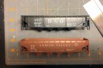
Side-by-side of an MDC car (left) and Atlas car (right) showing the slight length difference
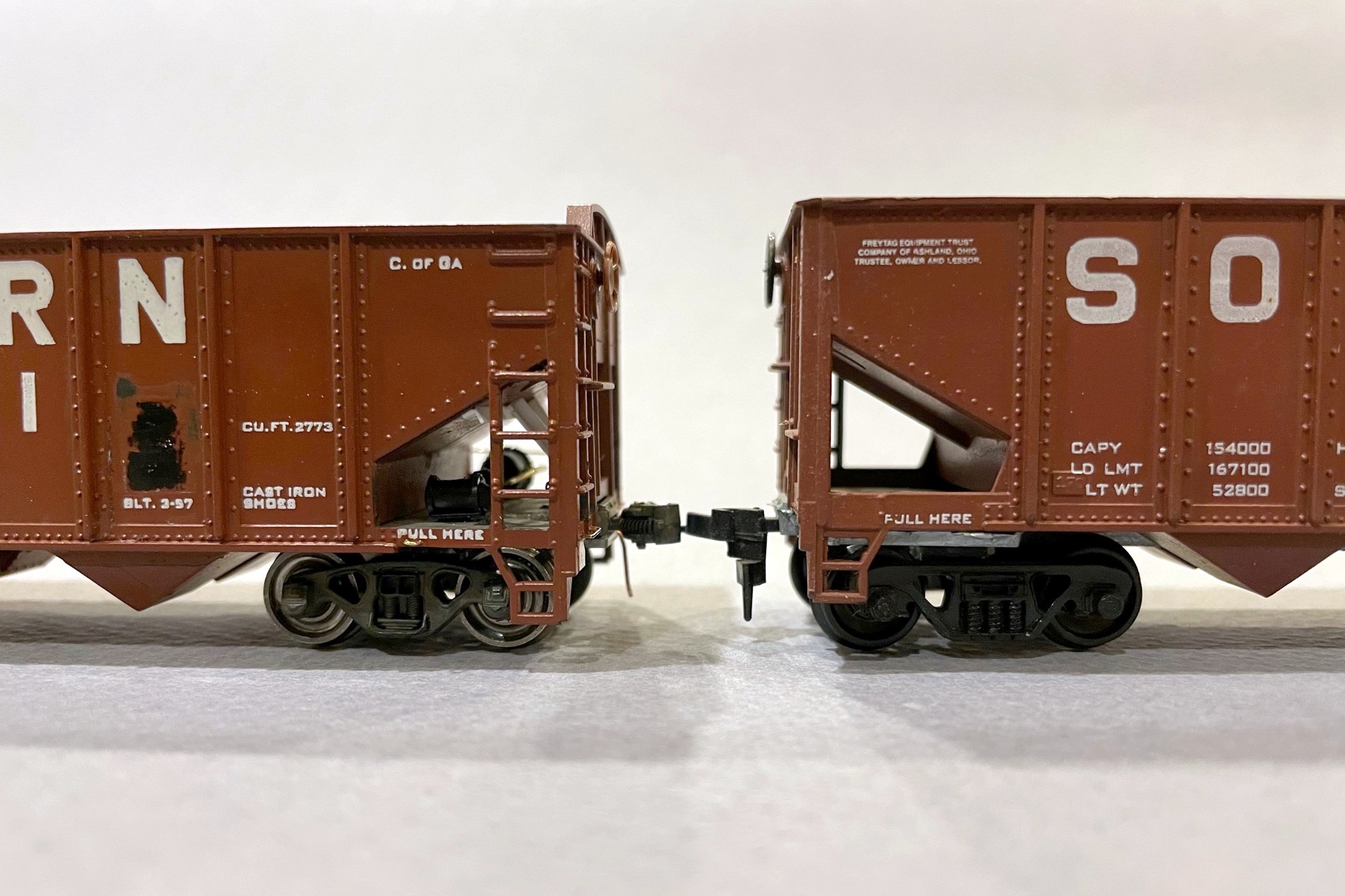
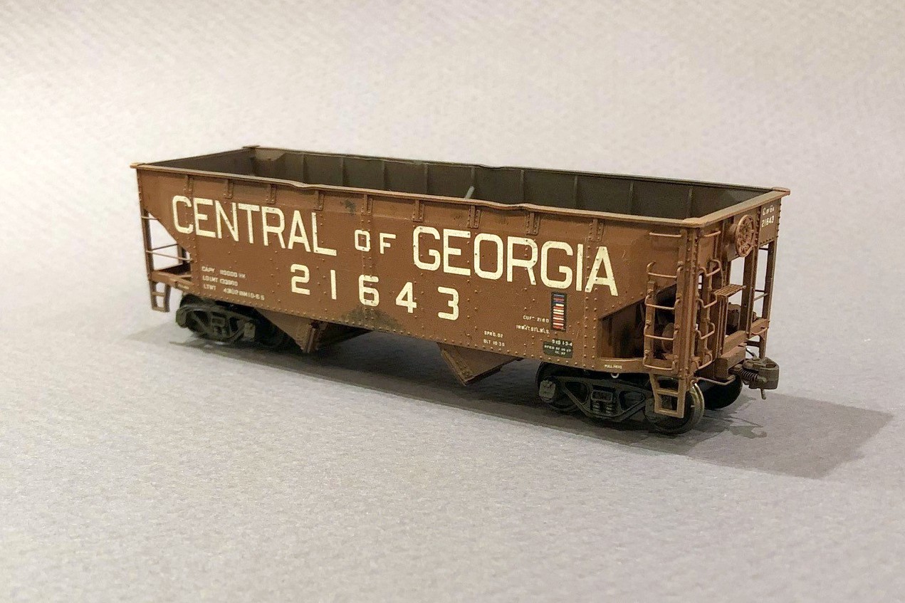
In the last post, I mentioned some of the work that went into creating an ex-Central of Georgia 70T rib-side hopper from an old MDC Roundhouse kit. Atlas makes a much more crisp and better operating out-of-the-box car in its Trainman 9-panel, 70T hopper that is a good stand-in for this car, but it’s about 2 scale feet too long. The Atlas kit, however, is a great model for the Southern’s mainstay fleet of 70T hoppers in the 70300-73749 and 281000-281299 series which far outnumbered the ex-CofGa cars in the 74100-74584 series–all you have to do is remove the heap shields and renumber them. The MDC Roundhouse kit can be picked up in Southern paint pretty cheaply. It’s a far WORSE model both dimensionally and detail-wise to match the Southern’s main fleet of 70T cars, but its overall dimensions are closer to the ex-CofGa cars. However, it requires a ton of work to make the car presentable in a string of more recently produced and more detailed cars. So, is it worth the work? Spoiler alert: it’s not worth it unless you’re just a crazy hopper person like me who notices the subtle length difference between these different series of cars in a long string of hoppers.
Ok, if you’re still reading, here’s a little more on what it takes to model one of the ex-CofGa cars using an MDC Roundhouse kit or one of the slightly improved Athearn versions. First, what’s wrong with the model out of the box? These molds are at least 40 years old, so the detail is sub-par–the rivets are clunky, the grabs are thickly molded, the brake platform and brake wheel housing is grossly under-modeled, the brake wheel is horrendous, and it’s just missing some details like the long grabs on the left ends of the car and bracing inside the car. Also, the bottom sills and corner posts are super thick at the ends. The interiors have an ugly scar right in the middle where the injection molding was done. The most egregious issue is also the most likely to escape notice (so I didn’t bother fixing it): the middle hopper bay is reversed with respect to the brake end. The lettering is not up to today’s standards but acceptable for a car that will be weathered, but there is no lettering on the ends of the MDC cars. The car also comes with arched heap shields that can be added, but they’re a little too short to look right, something that I initially ignored but eventually remedied by replacing them with parts off an Atlas car. It’s also missing details that were on the CofGa cars like slope sheet bracing on the ends.
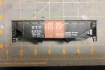
Detail differences between the original model (right) and the modified model–note the difference in the side sill width
I remedied most of these issues with an X-Acto blade. I started by removing the angles between the bottom sills and the side panels. Next I worked on the side/bottom sills and carved away excess material from the top and bottom with a No 11 X-Acto blade (leaving essentially just enough for the “PULL HERE” lettering). This was done to both the ends of the sides and the ends. I also removed the excess material from the left-side corner posts with a blade (I left the ladder side alone) and cleaned up the excess plastic in the steps. I narrowed down the ladder grabs with the X-Acto blade using repeated small cuts on the back side and alternating between top and bottom until the grabs were essentially round-ish instead of rectangular. I also used a chisel blade to remove the awkward rib down the center of the underside of the slope sheets. Finally, I removed the molded-on grabs from the lower ends adjacent to the couplers.
Details added include tack boards, grab wires, tow rings, cut bars, and train line
Next came the added styrene bits. I added some flat bits for the tack boards and the panels where the coupler cut bar would attach. Some large triangles (using the Atlas cars as a model) became the interior bracing. The most complex part was the slope-sheet bracing under the ends. I made these from three pieces of L-girder styrene and just dimensioned and cut them to resemble photos. I also replaced the brake wheels with more detailed Miner wheels from the parts bin (one Kadee and another whose origin is lost). I added wire grabs adjacent to the couplers, and added custom-bent long grabs on the left ends made from .012″ brass wire and tow loops made by bending .012″ brass wire around a thumbtack (I bend them into a “J” shape and just drill one hole). I bent coupler cut bars and eye bolts from .012″ brass wire using a little jig I made. I also added a couple pieces of brake-gear piping between the reservoir and triple valve bent from .020″ brass wire. The train line is a piece of copper wire from an old ethernet cable sandwiched between two pieces of L-shaped styrene. The final details included Kadee No 5 couplers, Intermountain metal 33″ semi-scale wheels (faces, backs and axles painted black), and arched heap shields salvaged from Atlas models (the in-progress photos here show the MDC arches which I replaced before weathering). Some careful carving and putty fixed the ugly scar on the center sill inside the car.
Detail differences on the ends
I wanted to renumber the cars and detail them for the early ’70s, so I removed a couple of the numbers and the black-and-white lube stencils the best I could by scraping them off with the back of an X-Acto chisel blade. I custom-mixed some paint to match the body and covered all the new details and scraped sides. I added the new numbers, ACI labels, and end reporting marks using a combination of Microscale, Herald King, and K4 decals. Now they were ready for weathering!
Interior detail including braces and covering up the injection mold scar
For weathering, I started with some drybrushing of dark rust spots in a few places on the sides. Next I airbrushed them moderately using a combination of flat black and dark tan airbrushing and washes. Since these are old cars that have been repainted, I went a little heavier than usual with the black on the interiors. I hit them with a wash of flat black paint and water, letting it sit for a minute and then wiping it off vertically to produce some rain streaking and shadows on the details. I used a wash of light orange rust and water on the interior and then added some drybrushed rust spots inside.
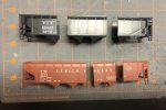
String of Atlas and MDC cars mixed in–the differences are subtle but noticeable
In all, these cars took probably 4x as long to detail and make layout-worthy as the Atlas Trainman cars. Now that they’re complete, I do like seeing the more stocky look of these CofGa cars mixed into a long string of Southern-heritage 70T cars. So much so that I’ll probably eventually go back and take all the heap shields off my Atlas cars and renumber them into non-CofGa series. Thankfully I’ve only completed 3 of these Atlas models, so it’s not a huge sacrifice. So, if you’re a hopper nut like me and nerd out on seeing the subtle differences between car series, then knock yourself out on a project like this! If you’re not a hopper nut, I recommend sticking to the Atlas models and saving yourself a lot of trouble.
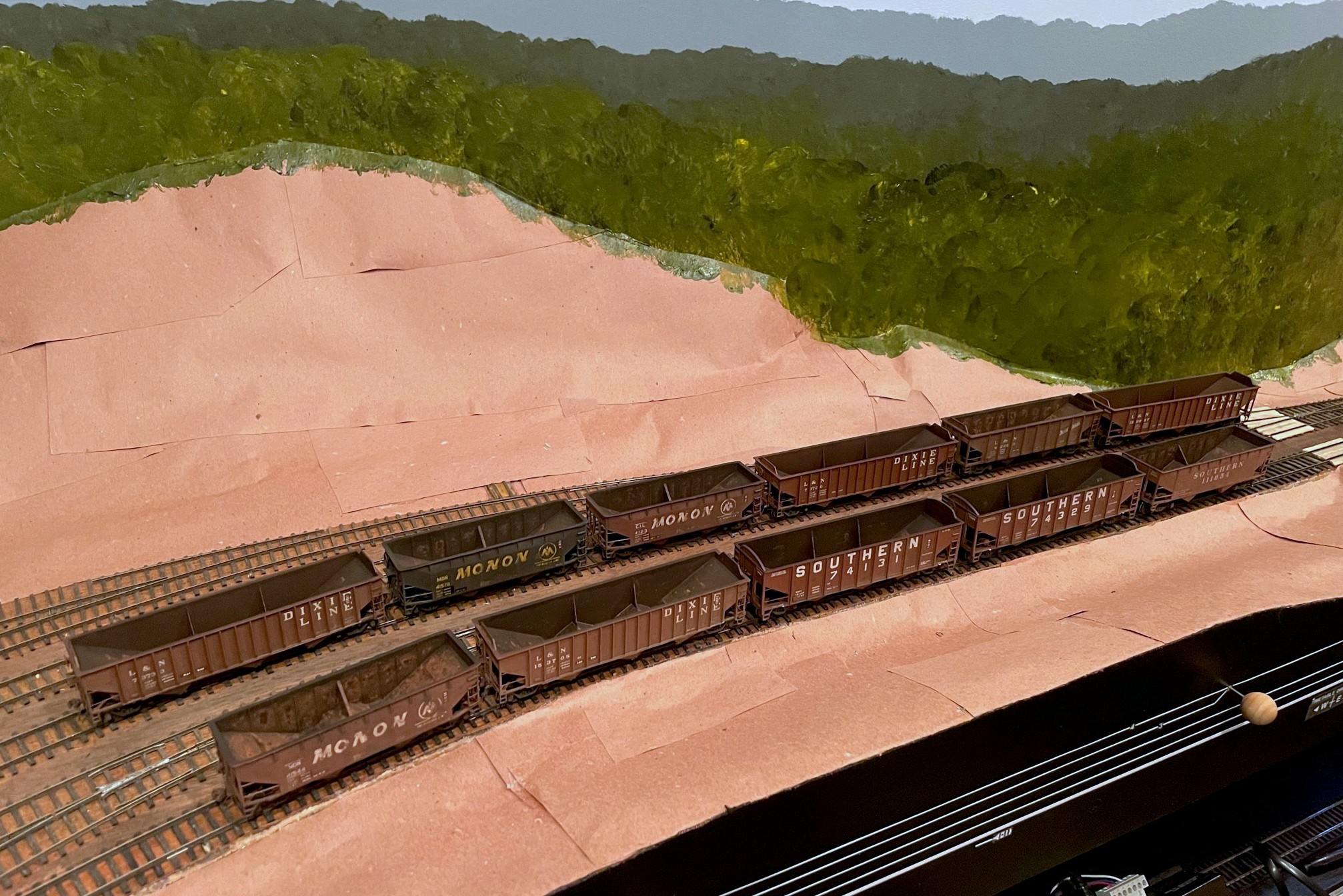
The hopper class of April 23 consists of 11 hoppers, mainly L&N and heritage cars
It’s time to introduce another “class” of hoppers graduating from the workbench to the layout. Looking back I see the last class of hoppers graduated in April of ’22, so I guess I’m averaging about a dozen hoppers a year… got a ways to go! This class was fun because most of the cars are for the L&N trains on the layout. Previous to this, most of my L&N cars were of mid-’70s paint and markings, so I focused on some cars to represent the mid-’60s to early ’70s including four PS3 70T cars, a PS3 50T car, and three ex-Monon two-bays (ok, I don’t need 3 Monon hoppers, but they came as a set, and I got them for cheap so…). The three remaining cars represent Southern prototypes including two ex-Central of Georgia 70T cars and an old 50T offset in red with Roman lettering.
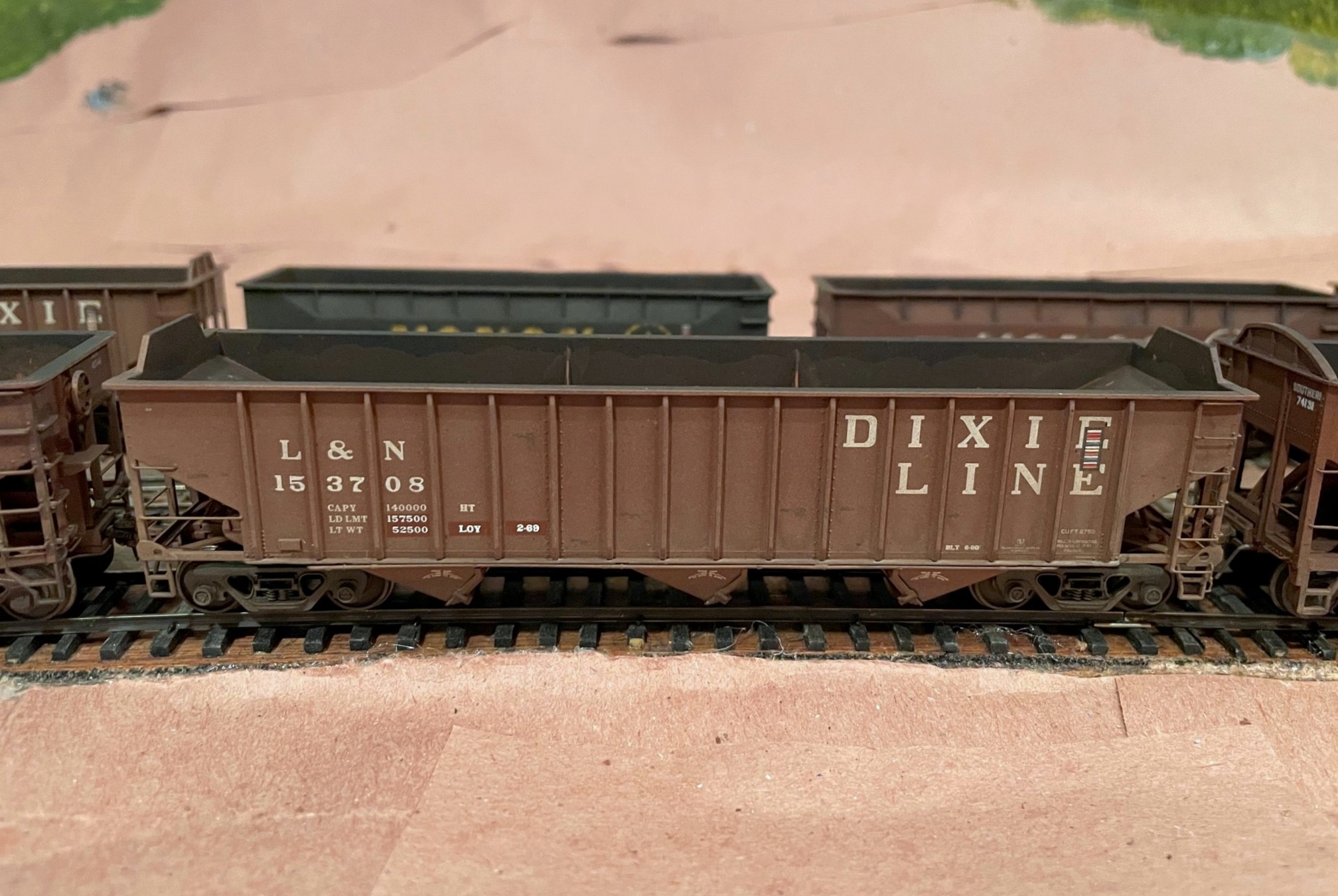
This Tangent PS3 2750 hopper received a new number, corner tow loops and roller bearing trucks to represent a later series of cars
The easiest cars of the bunch were the 70T PS3s which are all factory-painted Tangent cars with excellent detail. The four cars all came lettered in the 73000 series, and after looking through pictures, I decided they’d also be good to represent the 150000 and 153000 class cars that were also delivered in the “DIXIE LINE” paint scheme. For hopper 152067, it was as simple as changing the number and build dates. I scraped off the old lettering using an X-Acto chisel blade–it leaves a little shiny spot, but this is easy to disguise with weathering. Hopper 153708 was a little more involved because this class came with the later style tow loops at the lower corners of the car and roller bearing trucks. I snipped off the modeled loops, cut new corner tow loops from .015″ styrene, glued them on and painted them. A set of Bowser roller bearing trucks and metal wheels fit well and kept the car at the proper height.
This L&N PS3 is a factory painted Walthers Trainline kit that’s received new ladders and other details
The 50T PS3 is a factory-painted Walthers Trainline kit which is an updated version of a VERY old model kit that’s been around since probably the 60s and has pretty clunky detail. I remedied the worst of the detail issues by cutting off the ladders and replacing them with DA ladders and added new scratchbuilt heap shields. A new Kadee brake wheel and some new wire details like brake gear piping, grabs, cut bars and train line hose finished the detailing.
These three hoppers came in a single box from Atlas–they’ve had their details enhanced and have been extensively weathered but are otherwise stock
The Monon 50T hoppers are pretty much stock, factory painted Atlas hoppers. I used my favorite “grab narrowing” trick where I carefully cut away the back of the ladder grab irons with a sharp No 11 X-Acto blade. This makes the detail look much finer from any distance and is easier and quicker, in my opinion, than completely replacing the grabs with wire. I did add some wire grabs on the lower ends along with some cut levers and train line hoses.
Southern 50T hopper in Roman scheme weathered as if it’s seen a few miles
The Southern 50T offset hopper is a factory-painted Athearn model from a set of six (more of these to do). The roman lettering was common in the early ’60s and was almost entirely phased out by 1970. I wanted to model it in its last year or so of old paint. Detail-wise, it got the narrowed grab treatment, a new Kadee brake wheel, and a few wire details.
These two ex-Central of Georgia hoppers started as Roundhouse kits but are full of added and modified parts
The most work-intensive of the bunch were the two ex-CofGa 70T hoppers. These began as factory-painted Roundhouse kits (one used, one “new” but very old stock). Up to this point, I’ve been content to use the Atlas Trainman version of this car which is a pretty good stand-in. I also use the Atlas cars for my “primary” Southern 70T hopper fleet, and in reality, the Central of Georgia cars are 14″ shorter in length (40’6″) than the Southern’s big 70300-73749 class of cars (41’8″)… crazy me, I thought “wouldn’t it be cool to have the ex-CofGa hopper be noticeably shorter in a lineup?” Let’s just say these cars need a LOT of work to bring them up to modern standards and to correct the most egregiously noticeable detail faults and missing details. Lots of styrene, cuts, and extra details later, these cars emerged. Perhaps I’ll do a whole write-up on them [see the full write-up here], but they do, indeed, look cool and distinct in a lineup of Southern 70T cars… was it worth it? Only to a hopper freak like me.
I spent more time than normal weathering the interiors of these hoppers using a combination of airbrush, washes, and dry brushing
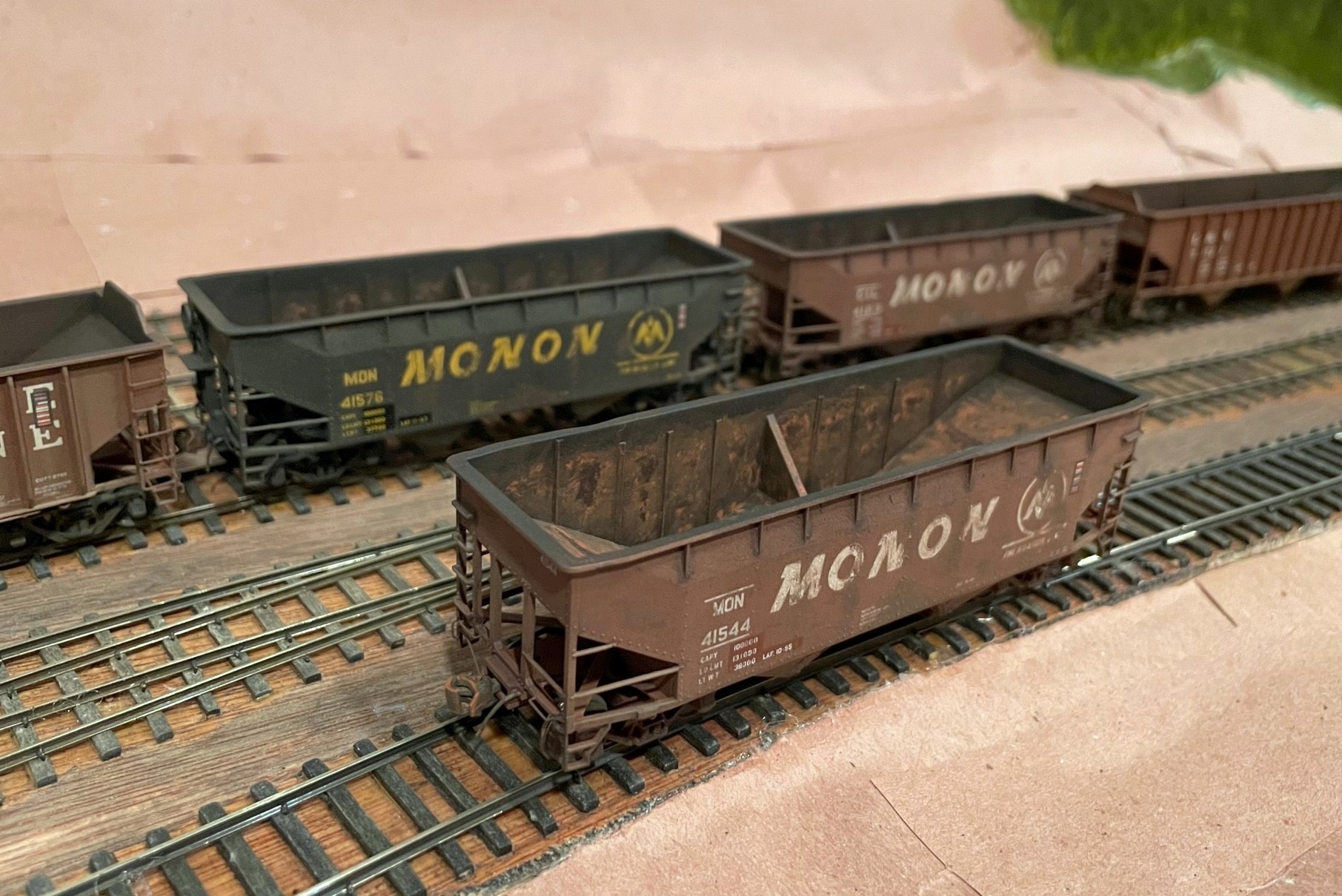
Most of these models represent cars that were already 10-25 years old when I’m modeling them, so they got some pretty heavy weathering. I did some dry brushing of rust spots on the exterior. The Monon cars got some car-colored dry brushing to fade portions of the big “MONON” using pictures as a guide. On several of the cars, I masked off portions of the data (LT WT and LD LMT) and shop markings with rectangles of tape–when peeled off after the airbrushing, it looks like re-stenciled data which is appropriate for cars this age. I airbrushed them all with a light spray of flat tan to fade them a little and add some dirt, especially around the trucks and bays. I also airbrushed some flat black into the interiors–the older the car being represented, the more black it got. Next I used a wash of black with a little tan on the outside to darken the seams and corners and dull things down. On the inside, I used a wash of Vallejo “orange rust” and water and dabbed it on heavily with a big brush, letting it dry in splotches and in the corners (some got a couple coats). For the oldest cars, I drybrushed the interior with orange rust, particularly along edges and panel lines. Finally, I put dabs of Vallejo “dark rust” into the centers of the orange spots to make it look like an old but growing rust spot with fresh orange rust along the outsides and dark rust in the middle.
Overall, I’m pretty happy with the additions, and it’s fun to have a few “rust buckets” running around in the trains. Can’t wait to load ’em at the next ops session!
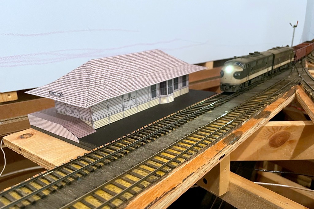
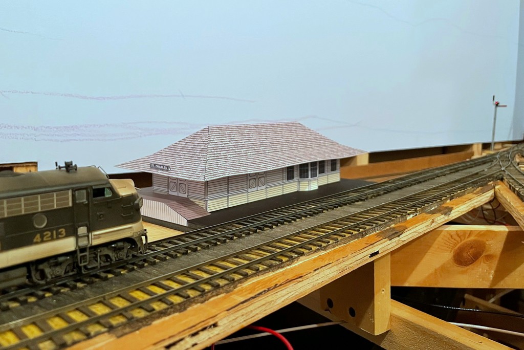
The St Charles local slows to pick up orders from the operator at the St Charles depot
This update is proof positive that I will do anything to procrastinate on building scenery… Of course, in my mind I’ve justified this delay as important because I need to be able to visualize the scene in St Charles before putting in the basic landforms. Sure, let’s go with that very logical explanation!
Several months ago I shared my plan to build mock-ups of the major structures on the lower level, the first of which was the Mayflower tipple which has appeared in many updates since it was built. I don’t want to build the permanent structures until construction on the upper deck is complete, but I’d like to have some of the key buildings represented both to visualize scenes and to give operators something better than just a block of wood to represent the buildings they’re working. Creating these mock-ups also requires me to build scale drawings (in MS PowerPoint) which, in theory, will make it MUCH easier to build the actual structures down the road. Of course, PowerPoint makes it easy to add colors and textures, so why not?
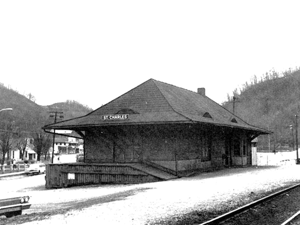
One of the few pictures I’ve found of the St Charles depot–it was darker, but I lightened it to see more of the details (photographer unknown, please tell me if you know so I can give proper credit)
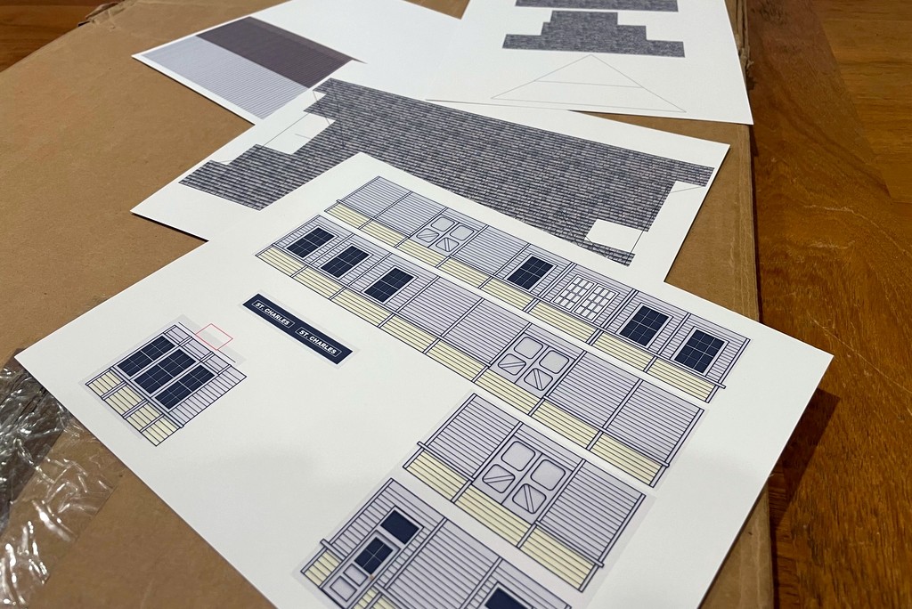
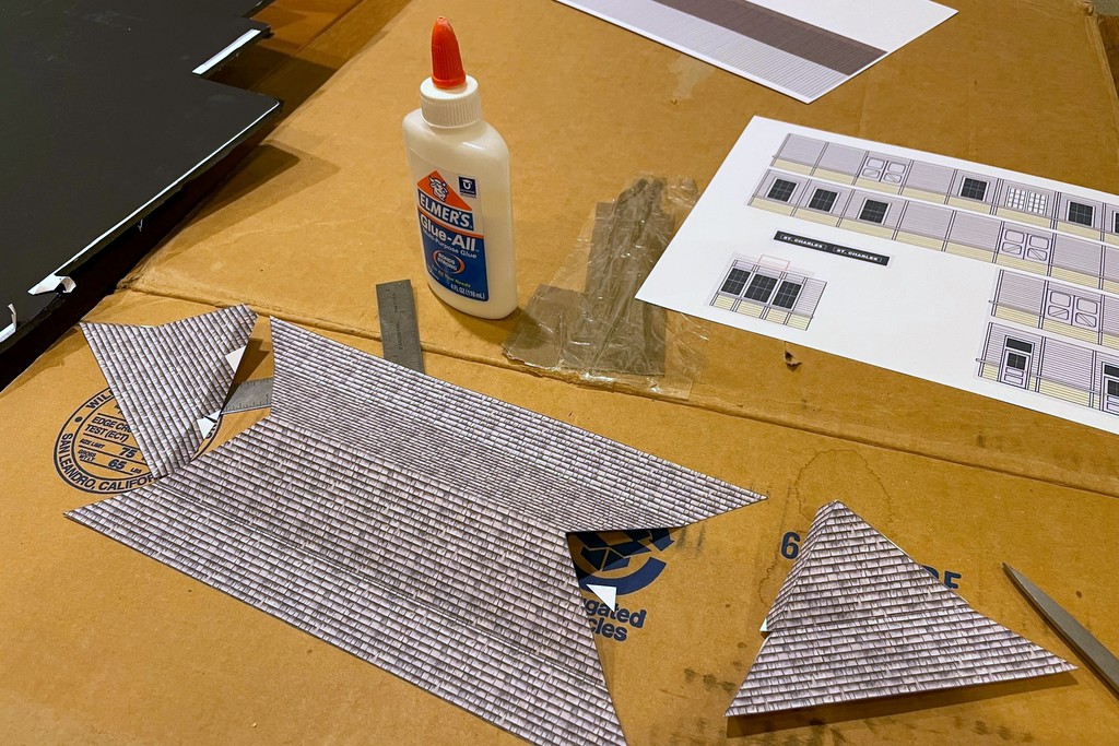
The St Charles depot burned down in the late ’70s, so there are very few photos of it. I worked with a couple of grainy shots and one grainy overhead image to get the basic size and layout. I used scanned plans from other Southern stations to get basic dimensions and features and to serve as a template for building the drawings in PowerPoint. I don’t have the space to model the station full-size, so I aimed for about 90% to scale on the length and about 70% on the width. The toughest part of the drawing was getting the cut angles for the roof right in a flat rendition so I could get the 3D shape correct. It required some trigonometry that made my brain hurt, but in the end I got a double-pitched roof with 22- and 35-degree slopes, pretty close to the drawings of other Southern stations. I omitted the curved roof windows for the mock-up as they would have been a pain and aren’t important to visualizing the scene. The detail like windows and siding is just lines and shapes drawn in PowerPoint, and the roof shingles are a texture I found online. Don’t ask me why the door on the track side of the station is suspended on the wall with no ramp or dock, but as you can see on the prototype photo, it is!
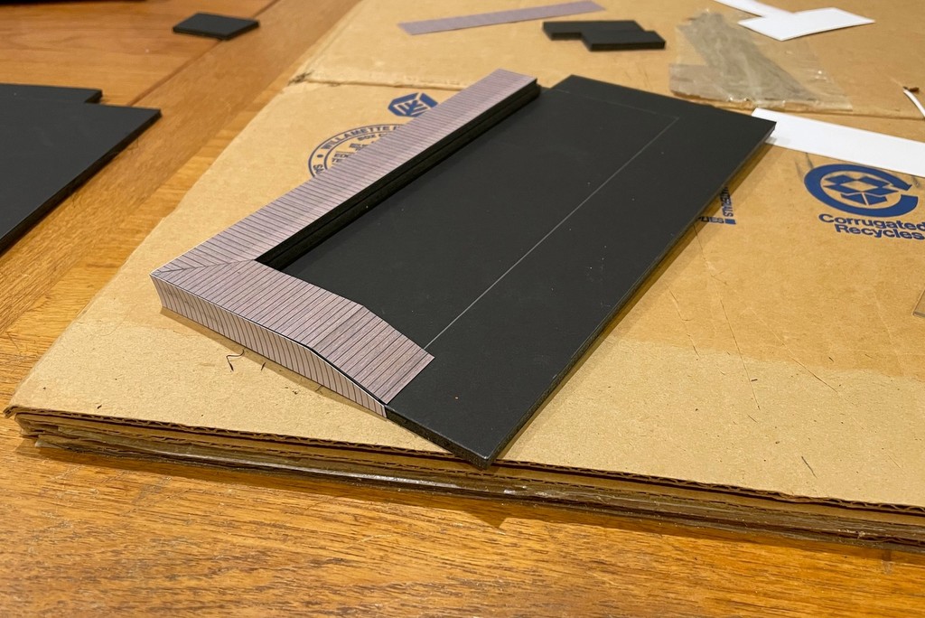
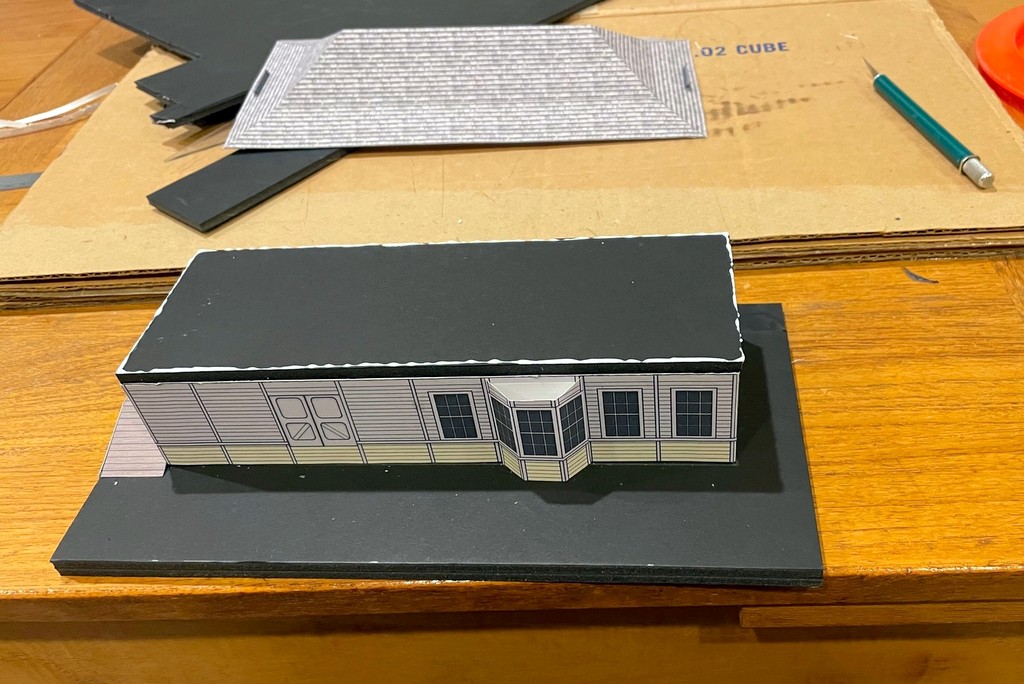
I used 1/4″ foam core to give stiffness to the basic structure
I learned from the Mayflower tipple that using ordinary paper results in the glue bleeding through and staining the color, so I printed this one on heavy paper, almost card-stock and about as thick as my printer would handle. I cut the basic walls out of 1/4″ foam core using the drawings as a template to give it rigidity, but the roof is just the card stock. I built a base and the loading dock on two sides using layers of foam core and covered parts with print outs of boards and vertical siding cut to shape. A couple of tiny “ST CHARLES” signs made from folded paper completed the mock-up. Everything is assembled with basic white glue. After it dried, I set it on a piece of plywood I attached to the sub-roadbed using spacers to level it on all sides–I figure this will make it easier to install the final structure level.
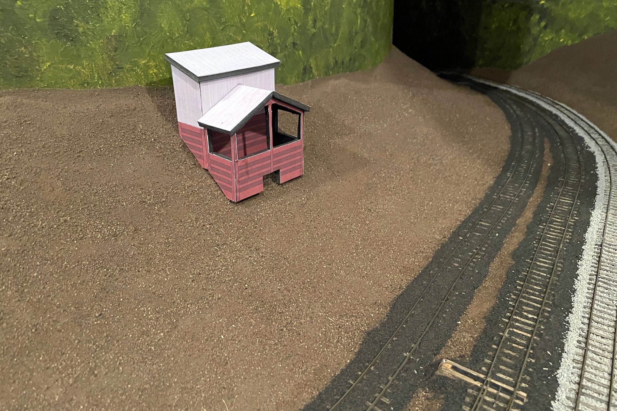
Now that it’s in place, I see that I need to raise the roof probably another 3/16″ which will be easy enough to fix in the final version [update, I raised the roof another 3/16″ as seen in the first photo, and it looks better]. For now, though, it’s great to have something anchoring the scene in St Charles, and I’m sure it will perform many years of dutiful service as I’m very slow. Oh, and if you know what colors the St Charles station was painted (there are clearly two), please leave a comment!
Here is the set of scale drawings flattened and printed on heavy paper
The toughest part of the drawing was getting the angles of the roof right… trigonometry in 3D… my brain hurts, but it worked!
I used 1/4″ foam core to give stiffness to the basic structure
The base and loading dock are made from layers of foam core with paper boards cut and glued to the edges
The original mock-up with the roof too low… didn’t look quite right
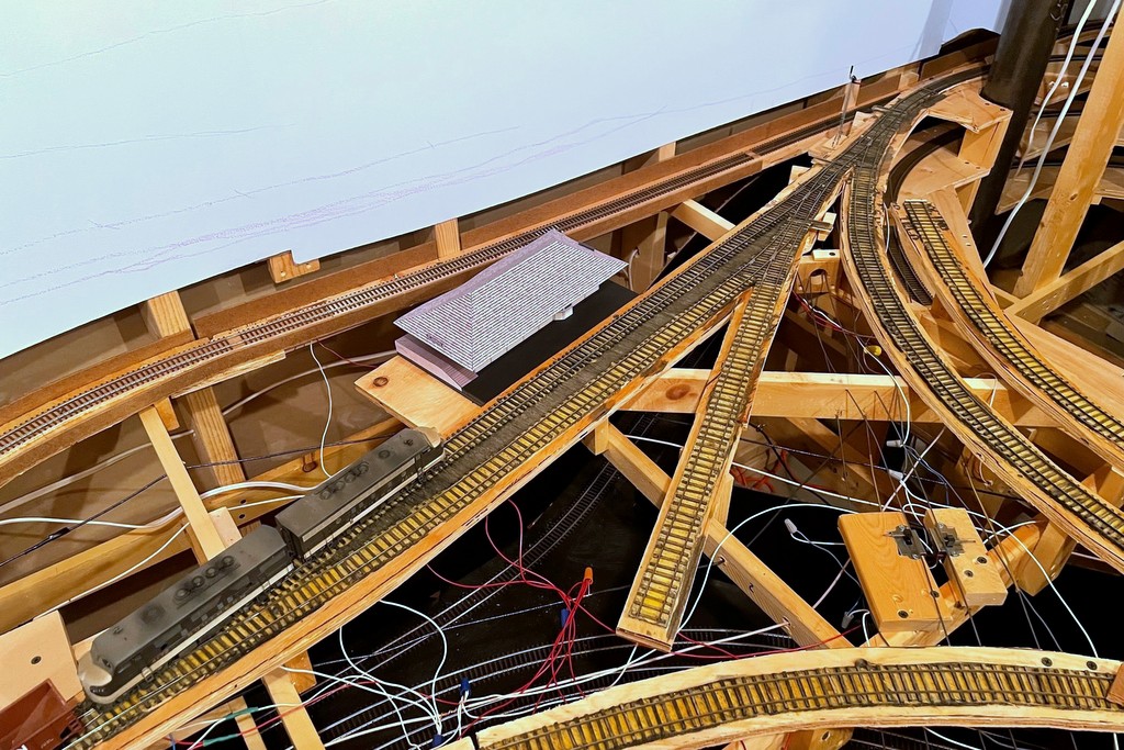
Bird’s eye view of the station scene–the track in the back will be hidden by a hillside behind the station
After letting the mock-up sit for a day, I decided to “raise the roof” to get it closer to prototype. I carefully removed the roof with an X-Acto blade and cut a piece of 1/4″ (really 3/16″) foam core to raise things a bit
The St Charles local slows to pick up orders from the operator at the St Charles depot
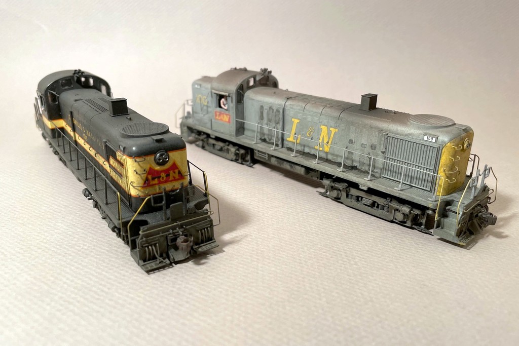
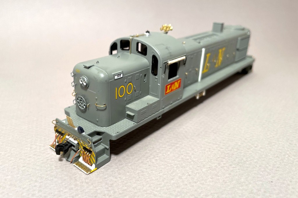
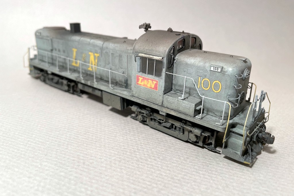
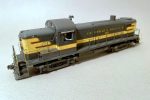
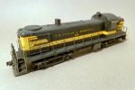
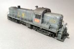
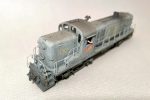
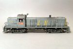
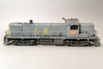
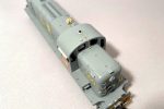
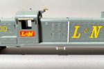
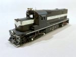
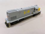
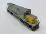
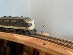
L&N RS3s 108 and 100, highly modified Athearn RS3s in original black and cream and early gray and yellow paint schemes
Standard diesel power on the L&N Cumberland Valley Local (CV Local) that served the St Charles Branch was a single RS3 until around 1974 when they were replaced with a single C420. The RS3 was the quintessential L&N mine run power of the ’60s and early ’70s, and these units sported a variety of paint schemes through the years. While the Phase III RS3s with rectangular carbody filters, prominent number boards and gyralights were more common, the early Phase IIs made regular appearances as well. I picked up two factory painted Athearn models a couple years ago to become CV Local power. I’ve been noodling on them for at least the last year, and the combined Southern Railway Historical Association (SRHA), L&N Historical Society (LNHS) and Railway Prototype Modelers (RPM) meet at Chattanooga, TN in October 2022 gave me the impetus to get these across the finish line.
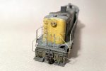
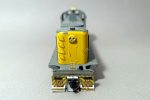
In-progress shot of L&N 100 showing some of the pilot and cab details
The Athearn models are decent, especially the body shape (old MDC shell), crisp paint, and fine handrails. The detail level, however, especially on the pilots, left a lot to be desired. I ended up scratchbuilding a ton of parts for these models which was actually a lot of fun and very rewarding! First things first, the black locomotive came as 102, and it had the original parallel exhaust stack these units were delivered with. I wanted 108 because it actually served as CV Local power in 1964 still in its original paint, so I scraped off the “2” on the long hood, scraped off the number-board decals, and replaced them with Microscale numbers from an L&N set. I also replaced the stack with a transverse stack from a spare shell and filled the old holes. For L&N 100, I “faded” the red L&N herald on the cab sides with a little wet sanding to make it look as though the red paint was wearing off and leaving the yellow underneath, something evident in many photos.
On the body, I scraped off the hood-door latches and replaced them with pieces of bent wire. I added some scratchbuilt lift rings to the long hood as well, and I bent new long grabs to curve around the hood ends as the factory grabs did not adequately capture their curves. I replaced the factory horns with some Overland 5-chime forward Nathan M5s as the factory horns were either incorrect or oversized. For unit 100, I scratchbuilt the antenna conduit and base from brass wire, eye bolts, and styrene with a DA whip antenna on top along with a scrap round cab-top vent from the scrap box. I also scratchbuilt the oil cooling coils under the right side (long-hood forward) from wire and styrene, and a piece of styrene rod completed the piping along the right side of the hood. The L&N units also had a rectangular hole below the third step on all corners, so I carved this out of the shell by drilling holes and cutting out the rectangle with a sharp X-Acto blade.
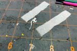
Step 1 of canvas sunshades is to bend the rod and attach a piece of tissue paper
One fun detail was the cab sunshades. The L&N used simple canvas sunshades that rolled around a bracket. My friend Stuart Thayer showed me years ago a canvas radiator cover for a switcher he made from tissue paper, so I tried that here. I bent the bracket from .015″ wire with the horizontal section about 5 scale feet wide. I cut a strip of tissue paper (Kleenex brand, to be exact) about 4 scale feet wide and very long for the canvas. There are 2 windows on the engineer’s side of the RS3 and 3 on the fireman’s side, but the bracket and sunshade appear to be the same size. To adjust for the window spacing, I centered the canvas on one bracket and shifted it toward the rear of the cab for the other to cover the third window. After attaching the end of the “canvas” to the bracket with CA and letting it dry, I rolled the tissue tightly around the bracket a few times, cut the end off, and secured it into a roll using CA. A little black paint for the bracket and sand-colored paint for the canvas finished the project.
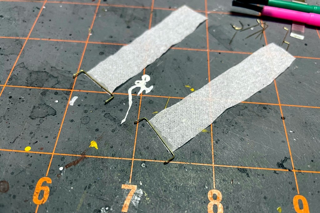
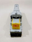
In-progress shot of L&N 100 showing pilot details including copper-wire MU hoses and scratchbuilt pilot steps
The pilots on the model are very bare with grabs in the wrong spots and no MU detail. The first detail upgrade was to scratchbuild some simple MU hose boxes and the angle on top of the coupler box from strips of styrene. This left the footboards too short, so I made new footboards from some brass roofwalk material and styrene. For the MU hoses, I decided to bend my own using one of my favorite modeling materials, copper wire from some old Cat 5 ethernet cables. I simply drilled holes into the pilots, bent the MU hoses, cut them to length, and glued them in with the ends in the hose boxes except for a few hanging out which I cut a little longer and pinched with pliers to simulate glad hands. The coupler cut bars are also a first for me. Rather than the U-shaped bracket over the coupler I’m used to, the L&N’s RS3s had a single long rod extending from the pilot with an eye bolt on the end. I scratchbuilt an impression of this from eye bolts and bent .012″ brass wire. Some formed wire and an eye bolt also formed the safety grab across the top of each pilot. The final pilot details were an MU cable receptacle (scrap box parts from Proto GP7s/9s) and scratchbuilt drop steps. The drop steps on 108 are solid pieces of sheet styrene cut to shape and rounded with a file. The see-through steps on 100 were made from brass roofwalk material.
For the underbody, I added the equipment boxes on the fireman’s side next to the fuel tank. For 108, I scratchbuilt this detail using several pieces of sheet styrene. For 100, I recycled a piece I’d cut from an ancient Athearn U33C shell when I’d narrowed it to make an L&N U30C. For the trucks, the biggest detail was the speed recorder on the fireman’s side. I scratchbuilt this detail using a piece of sprue for the main cylinder, styrene rod to attach it to the truck (after pulling off the journal box and exposing the square hole), and styrene rod filed to a rounded point for the center piece. The cable is copper ethernet wire bent to shape and held to the sideframe with an eye bolt.
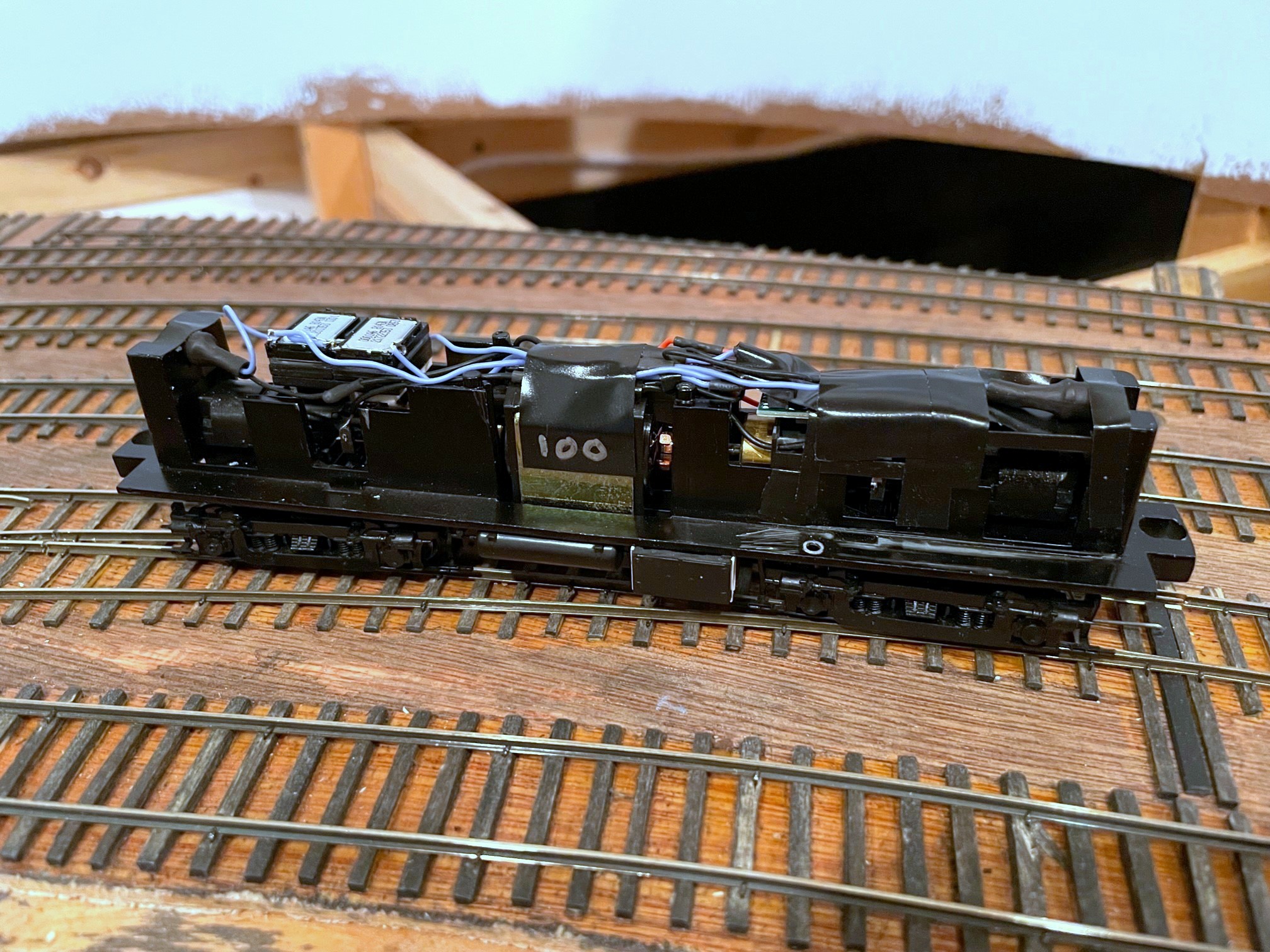
The tight quarters inside an Athearn RS3–the decoder is under the cab to the right side
Perhaps the most challenging detail modification was the end railings. The factory railings have MU stands that were easy enough to trim off, but the L&N used squared-off outer railing supports instead of the angled versions on the factory model. Engineering plastic is notorious tough to work with, so I hemmed and hawed over just leaving the factory angle before deciding that the squared look was distinct enough to warrant the effort. I started by using the corner of a file to notch out the 135-degree angle I would need to bend to 90 degrees to make it more pliable. Next, I cut the lower attachment spot of the angled support and cut the angled piece slightly shorter so it would bend to 90 degrees without overlapping the stanchion. Next, I roughed up the side of the stanchion so it would better take CA and glue (it doesn’t really “take” glue well even with roughing, but it does still better than leaving it slick). Finally, I cut a small piece of styrene to wedge alongside the stanchion and hold the angled piece at 90 degrees and secured everything as best I could with CA and liquid model cement.
On the inside, the toughest thing was adding sound. There is hardly any room at all inside the shell, so I had to make several compromises. I chose a 21-pin Soundtraxx Econami decoder because it’s very small, and the Alco 244 sound it produces is pretty decent. There is only one ideal open spot inside the shell, so I decided to use it for the speakers, a pair of LokSound 11x15mm “sugar cubes” wired in series with the small LokSound baffles installed. This meant the decoder needed to go in the cab section. This required me to cut away the center section of the body within the cab to allow the decoder to sit on top of the truck assembly and extend into both the long- and short-ends of the hood. This is not a 21-pin model, so I made a custom 21-pin harness by soldering short bits of wire that fits snugly into the decoder holes onto the locomotive wires.
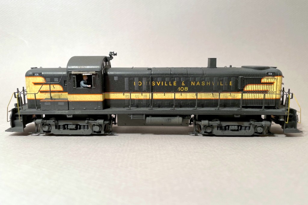
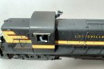
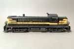
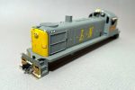
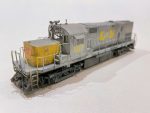
Finished L&N RS3 108 from the right side
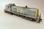
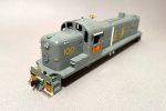
Once all the details were in place except the handrails, I touched everything up with black paint on 108 and gray paint I mixed to match 100. For 108, I was weathering to pictures of 108 on the CV Local in 1964 (see Ron Flanary photo here)–the fading on the roof is apparent, but the paint is otherwise fairly intact. I weathered 100 to pictures of it at DeCoursey Yard in Cincinnati in 1972 (see Brian Woodruff photo here), and it’s filthy! The first thing I noticed was 100’s factory paint was too dark. To “fade” it, I used a lighter gray and airbrushed it to lighten it up significantly. I wish I’d taken a picture of this step so you could see how much lighter it was–the weathering darkened it back up again, so I’m really glad I lightened it beforehand! I also sprayed a little dark gray onto the top of 108 to simulate fading, and I sprayed a little dark rust color onto both roofs and in front of the stacks and drybrushed some streaks under the battery boxes. Next, I gave them both a good black wash to grubby them up a bit. 100 also got some “oil stains” along the bottom of the carbody and in some of the hood door louvers. I’m happy with the lower oil stains but not the louvers–in retrospect I should have continued more layers of wash rather than using a thicker (but still watered down) black as it didn’t wipe off cleanly… my story is someone tried to wipe off the oil, and it just smeared… This model’s weathering is actually “backed off” a little from prototype photos to represent ~1968-70, believe it or not!
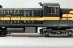
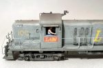
L&N RS3 100 left rearL&N RS3 100 showing cab details including engineer and canvas sunshade
After the washes and oil stains, I put the handrails on and added liberal sprays of tan and flat black to weather the pilots, trucks and fuel tanks. I also used tan lightly on the lower sides and top, and I used flat black liberally around the exhaust stack and lightly on the rest of the roof. At this point, all that was left was to reinstall the windows, add wipers, and paint and insert the engineers (two bicyclists from a Preiser kit) which required amputation of the left legs to get them between the cab sides and body sides. They add a lot of interest, and as these units always operated solo on the CV Local, it made sense to add them. The final details were headlights made from bits of fiber optic cable with the end melted into a lens shape and some cab wind deflectors, simple bits of leftover clear styrene packaging cut to size and painted on the back and edges.
So now between these RS3s and C420 1317, I’ve got sufficient L&N power to run the CV Local from about 1962-1977. I still plan on modeling a couple of PhIII RS3s at some point, to include one in boring spartan black (sigh…), but at least the L&N crew on the layout will have some nice-and-dirty locomotives to go with the gurgly and lumbering burble of the Alco 244 prime mover as they shift hoppers around the coal fields of southwestern Virginia!
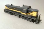
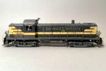
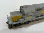
L&N RS3s 108 and 100 illustrating how much more the gray scheme shows weathering than the black
L&N RS3s 108 and 100, highly modified Athearn RS3s in original black and cream and early gray and yellow paint shcemes
Finished L&N RS3 108 from the right front
Finished L&N RS3 108 from the right rear
Finished L&N RS3 108 showing cab details including canvas sunshades and engineer
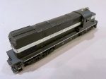
Finished L&N RS3 108 showing underbody details including the scratchbuilt equipment box along the tank and the scratchbuilt speed recorder
Finished L&N RS3 108 from the left rear
Finished L&N RS3 108 from the left front
Finished L&N RS3 108 from the left side
Finished L&N RS3 108 from the right side
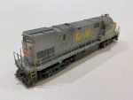
L&N RS3 100 right front
L&N RS3 100 left rear
L&N RS3 100 showing cab weathering
L&N RS3 100 showing finished pilot details
L&N RS3 100 showing cab details including engineer and canvas sunshade
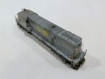
L&N RS3 100 right side showing heavy weathering and oil stains
L&N RS3 100 left side
In-progress shot of L&N 100 showing grab irons and long-hood latches
In-progress shot of L&N 100 showing some of the pilot and cab details
In-progress shot of L&N 100 showing pilot details including copper-wire MU hoses and scratchbuilt pilot steps
In-progress shot of L&N 100 showing cab and antenna details
In-progress shot of L&N 100 showing scratchbuilt piping
Step 1 of canvas sunshades is to bend the rod and attach a piece of tissue paper
Step 2 of making canvas sunshades is to roll the tissue paper tightly and seal it with CA
The tight quarters inside an Athearn RS3–the decoder is under the cab to the right side
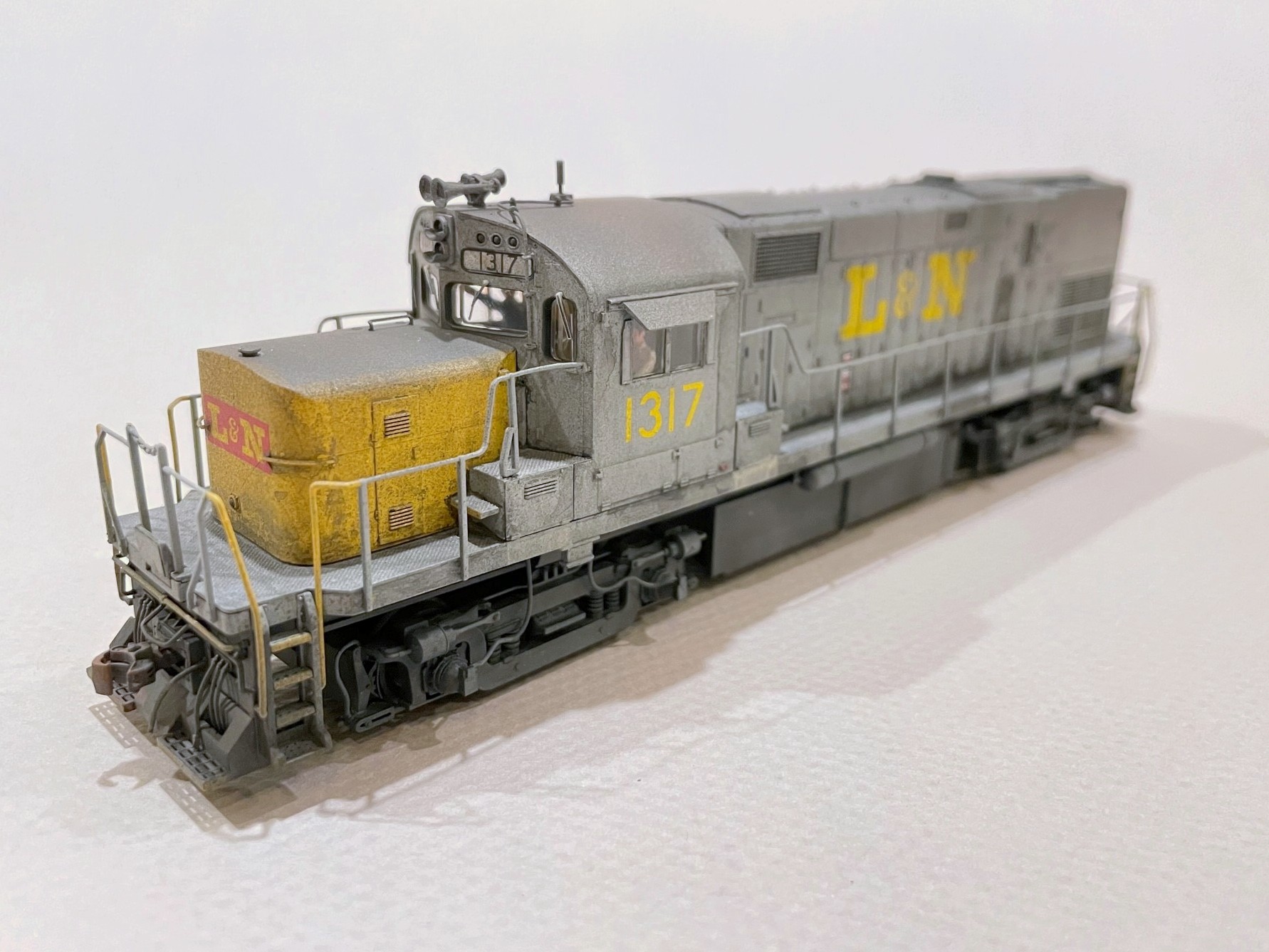
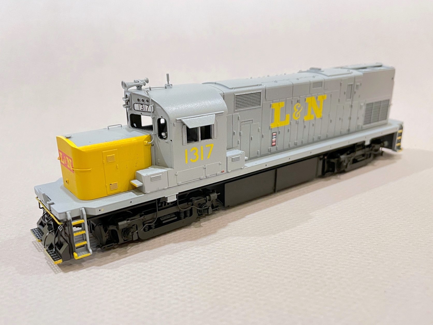
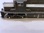
The Louisville and Nashville served the end of the Southern’s St Charles Branch via trackage rights, and the train that did the honors in diesel years was known as the Cumberland Valley Local or “CV Local” for short. This train, which also served the mines near Middlesboro, Kentucky, was usually meager in terms of tonnage, and a single locomotive was sufficient for the task. For my eras, the CV Local was usually handled by a single Alco RS3, and after 1974, a single Alco C420. Due to weight restrictions on the “Old CV” where this train roamed, the favorite C420s were 1316 and 1317, two ex-Tennessee Central units that happened to be the lightest C420s on the railroad. Needless to say, modeling one of these units has been on my list since I started building the St Charles Branch. So, meet ex-TC C420 1317 in HO scale!
LN C420 1317 pre-paint wheel slip sensors
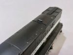
This model started as an Atlas Phase 2b C420 in factory-applied TC paint (why not?). While the Atlas details are pretty good out-of-the-box, there were a few things the model needed to be an accurate representation on this particular unit. Most noticeably, the TC units had very narrow, rectangular fuel tanks (part of what made them so light). I simulated this by removing the rounded sections of the Atlas fuel tank, separating the air reservoirs (I’d need them later), and patching the holes. The tank is still about 18″ too wide, but it gives the impression created by the narrow tank and makes this C420 stand out in a line of round-tank Alcos. The drain pipe on the left side is just a piece of Cat 5 ethernet cable with the insulation intact and a few bits of styrene for the bracket.
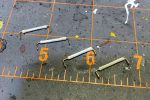
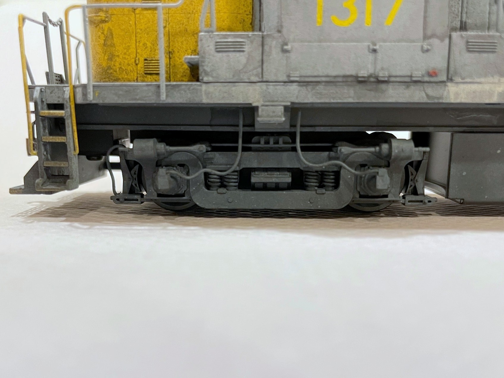
A few of the details are commercially available detail parts including a DW brass horn and DW air filter (added just before weathering where the bell was previously). Most, however, are homemade from bits of styrene, brass wire, and one of my favorite modeling materials, copper wire from old Cat 5 ethernet cables. The most challenging details were the wheel slip sensors that go over the four truck journal boxes on the left side of the locomotive. For mine, I used bits of sprue filed into a conical shape for the base. Next, I drilled a hole through the center big enough for the copper wire (stripped of insulation). I bent the copper wire so it extends through the truck sideframe to help prevent the assembly from being broken off. From there, the wire bends up and then toward the middle of the sideframe where I bent it into a sagging shape per photos. Next I used bits of styrene to frame the wire on top of the conical housing and then to cap the frame to simulate the portion where the wire comes into the housing. Similarly, I bent bits of copper wire into the shape of sand lines for the pilot end of each sideframe (there’s not enough room on the fuel-tank end).
LN C420 1317 pre-paint cab details
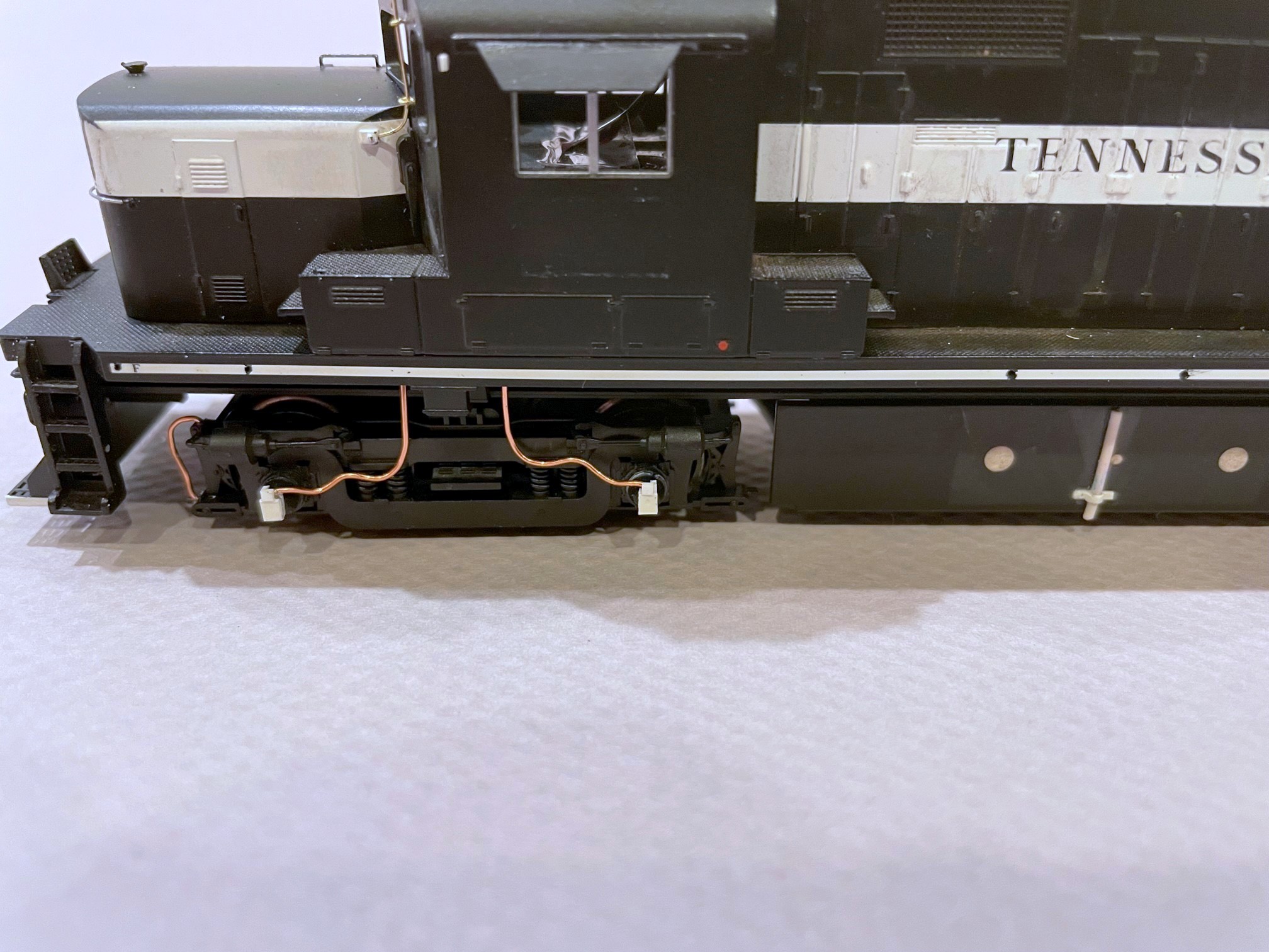
The next most challenging detail was the antenna conduit. Photos are clear that the L&N added a long antenna conduit from the nose to the roof along the cab face. I couldn’t find any roof shots of 1317, so I inferred the rest from other units: 1) conduits are usually paired with a box under the antenna on the L&N, and 2) firecracker antennas in the center of the cab roof are the most common. The conduit was carefully bent from .012″ brass wire and held in place by eye bolts (these happen to be homemade as well from .010″ wire). The base is a cube of styrene, and the firecracker antenna is just a piece of copper ethernet wire with the insulation partially removed (thanks to my friend Stuart Thayer for teaching me this trick). Rounding out the initial cab details are some sunshades out of the spare parts box and a couple of headlight deflectors made from bits cut from the “ears” of a Kadee coupler box.
The roof of the model has molded-on lift rings, and I decided to shave these off and replace them with wire. I used .010″ wire bent around a thumbtack to create candy-cane shaped lift rings–only the long end is actually inserted into a hole, the other side is just pressed into the body a bit. For the pilots, I reused most of the Atlas factory parts including the MU cables, coupler cut bar and long grab. I also used the factory drop steps but added a piece of thin styrene to make it solid instead of a grate per prototype photos. The train line hose, like my freight car hoses, is – you guessed it – a piece of copper ethernet wire bent into shape and crimped at the end to form the glad hand. Finally, just before painting, I noticed that the L&N had removed the hand brake from the front of the cab, so I did the same, replacing it with a square-shaped length of styrene and a hole.
LN C420 1317 painted left front
Before painting, I sanded the TC paint lightly to remove some of the sheen and “3D” nature of the striping, but I left a little of the raised paint so at certain angles you’d be able to still see the faint lines of the TC paint (again, why not?). I still have a lot of Testors Model Master acrylics, so after examining photos, I decided on “light ghost gray” for my base color and “insignia yellow” for the nose. I primed the whole locomotive with black and then masked the pilots before airbrushing the gray. The nose was easy because it’s a separate piece, so all I had to do was spray it gray, mask the rectangle for the top, and spray the yellow. I used a combination of a black sharpie and brushed black paint for the window and number-board gaskets, and a little blue and red paint for MU covers, fuel fillers, and a couple other things on the gray that look red in photos. Marker and walkway lights are just semi-gloss black paint. The final step was spraying the painted shell with Rustoleum clear “high luster” lacquer to protect the paint and make a better surface for decals.
I used the Microscale set 87-823 “L&N Locomotives Gray & Yellow 1970-80” for most of the decals, using dozens of liberal coats of Micro-Sol and Micro-Set and a damp paper towel to help the decals settle in. The numbers on the number boards are from a Microscale SCL diesel set–they’re a little smaller and look better on Alco boards. One detail I added during this step was the cab wind deflectors flanking the side windows. These are just bits of clear styrene from an Intermountain wheel box. I cut a strip the width of the deflectors, masked a strip down the middle, painted the back the gray color of the body, and used a silver Sharpie marker on the sides and around the masking. After removing the masking tape, I cut the deflectors to length, added a little dog-ear, and used the silver Sharpie to hit the cut ends. A dab of CA on the cab secures them in place. This method models an otherwise delicate detail in a manner that’s resilient to routine handling on the layout.
LN C420 1317 finished wheel slip sensors
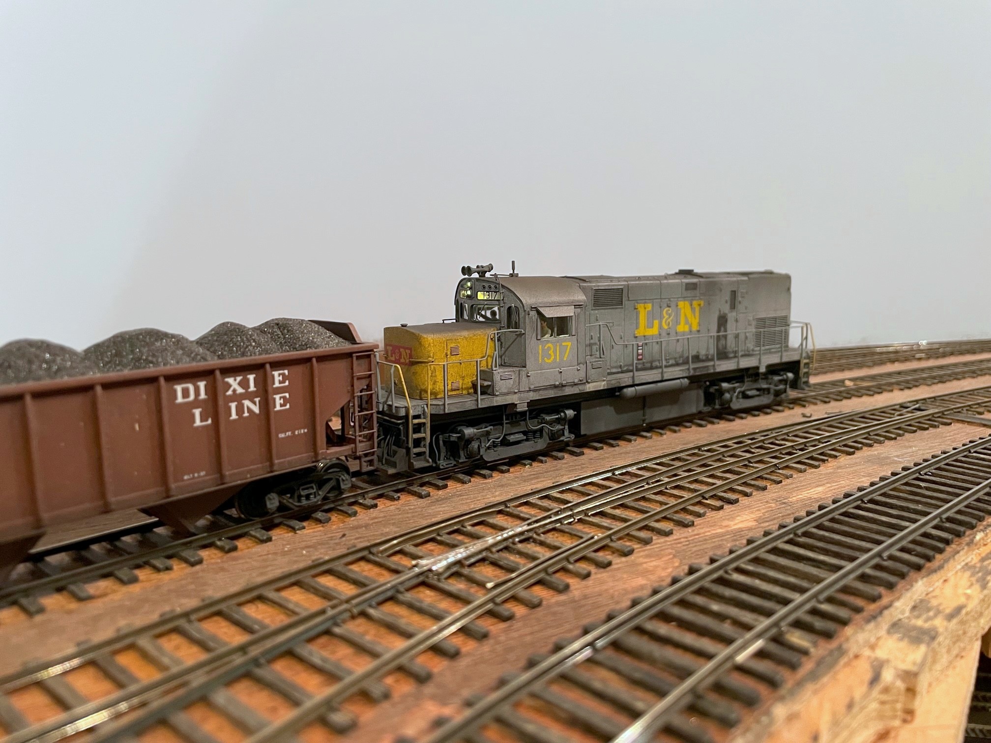
Weathering on this unit, as you can see, is substantial–these units worked the coal fields, and baths are few and far between. Besides, part of an Alco’s charm is it’s ability to spew oil and black smoke everywhere. Working from photos, I started with the oil seeps on the engine doors–these are mostly around the bottom, but in two photos from 1974, an entire door on 1317’s left side was covered in oil, so I modeled this. I used watered down flat black paint, alternately dabbing paint and water to get the consistency right and wiping in a vertical direction between coats. Next came several black washes of water with some black paint mixed in. I brush it on in a section, wait 30-60 seconds, then wipe in a vertical direction to simulate grime streaked by rain. The trick is to do multiple light coats until you’re happy. A little drybrushed sand color under the battery boxes finished the preliminary weathering.
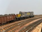
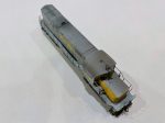
LN C420 1317 working Mayflower on the CV Local
I left the handrails off until I was ready to airbrush. Airbrushing consisted first of some tan sprayed heavily on the pilots, trucks and fuel tanks (with the air reservoirs now mounted). Next came flat black primarily on the roof–moderate in most areas and thick around the exhaust stack. Finally, I used a little rust on the pilots and roof to give it just a bit of a rusty brown look. All that remained at this point was to reassemble everything, including the cab glass that had been removed earlier, and add a set of A-Line windshield wipers painted silver.
Overall, I’m very happy with how 1317 turned out, though I think I overshot the weathering a little. The unit was repainted in 1974, and I was shooting for weathering circa 1976. I think I nailed the weathering circa 1978, but it’s still a pretty realistic representation of how filthy these Alcos got in the L&N’s coal fields during the coal boom. This is also the first Alco I’ve ever finished, so I also enjoyed the challenge of making so many details from scratch. The unit came with factory sound by Loksound which does a great job of replicating the lumbering burble of the Alco 251 prime mover, so she’s a blast to operate! I’m just happy the CV Local finally has a finished L&N unit to head it up which should make the next ops session more fun.
The 16 hoppers of the April 2022 class finished and ready for the next session
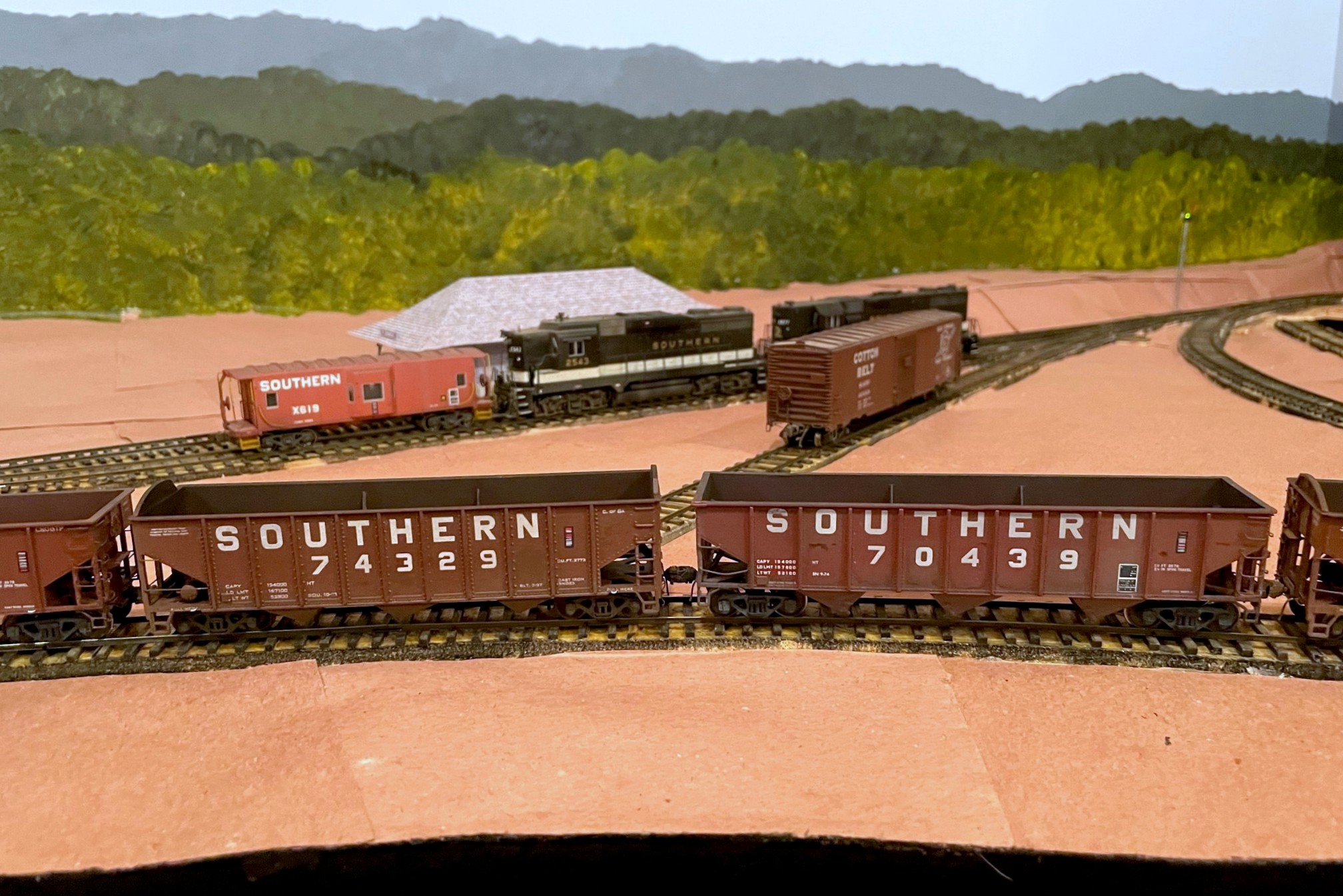
The St Charles Branch would like to welcome the Southern Hopper Class of April 2022 to the roster! The 16 cars in this graduating class are the largest group of cars I’ve ever finished at one time (and probably the largest group I’ll EVER attempt at one time). The 16 hoppers, including a foreign exchange student from the Clinchfield, represent cars across the layout’s range of ops session eras from mid ’60s (cars still in roman font) to the mid ’70s (brand new 100T hoppers). Consequently, all were weathered a bit differently from a 55T twin with dents and lots of grunge to brand new with just a little grime on the trucks and underside.
A Tangent 70T PS3 clone next to an upgraded Atlas Trainman car
A few of the cars (CRR 70T and 50T extended-height war-emergency rebuild) have been complete and just awaiting weathering for several years. Some of the cars have been running on the layout for a while but didn’t yet have their full set of details or weathering. The bulk of the cars are Atlas 70T Trainman hoppers, which I love because they’re relatively cheap but have good wheels and trucks and great paint for budget cars. Some Trainman hoppers got a full set of new grabs (did this a while ago). Most Trainman hoppers (along with a pair of Bowser/Stewart 12 panel hoppers) got the standard treatment of getting the grabs shaved down to a more reasonable thickness front-to-back using an X-Acto blade. Other added details include Kadee #5s, plastic bits for tack boards and door bars, wire grabs adjacent to the couplers, homemade tow loops, homemade train lines (copper wire from Cat 5 cable), and homemade coupler cut bars (bent from .012″ brass wire on a homemade jig). A few got dents added in the top sill by softening them with a 100W lightbulb. A few of the cars came with heap shields (correct only for a small number of ex Central of Georgia cars) that got removed as well. I also swapped out the trucks on the Tangent 100T cars–I decided I wanted cars that roll well more than neat spinning roller bearings.
Two of the more heavily weathered hoppers of the batch–note the dents in the top sill of 70439
All but one of these cars is factory painted which saves a TON of time. I changed some of the numbers by scraping them off gently with an X-Acto chisel blade (along with the later round “O”s on some of the Atlas cars) and replaced them with decals. Most cars received ACI labels (1967+) and a couple got lube plates (1974+). Before weathering, I covered some of the weight and shop stencils with rectangles of masking tape to represent re-stenciled cars. I ran them through a weathering assembly line that included coats of various thickness of airbrushed flat black followed by light tan. I then painted out a few more weight panels with fresh oxide red and added some stencil data in a different font to a couple cars. A few of the cars got some drybrushed rust marks too. Finally, most of the cars got a wash of flat black inside and out. Overall I’m really happy with how they turned out, but I don’t think I’ll ever assembly line 16 cars again… do you know how many wheel faces that is to paint? 16 cars x 8 wheels x 2 faces per wheel = a ton of wheels (that’s 128 wheels and 256 faces… don’t hurt yourself doing the math)! Still, it will be worth it to see coal trains with a lot fewer shiny cars in the mix.
The Tangent hoppers represent cars built in 1975 so weathering is minimal
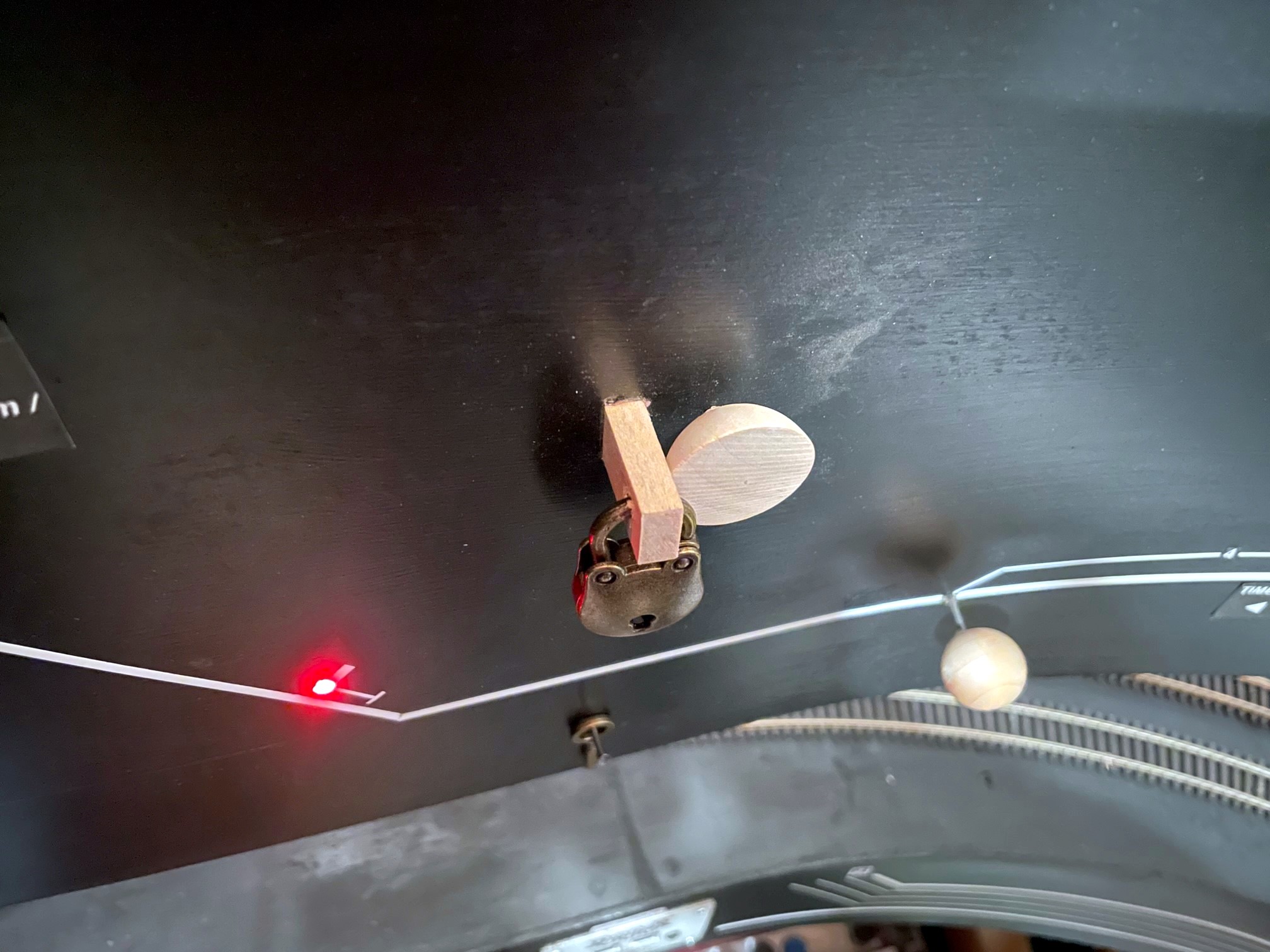
The Black Mountain Local stops to reset the dwarf semaphore now that their work is complete
Semaphores were a common way of signaling trains on the Southern Railway. Semaphores were often used at stations to indicate whether or not the train was cleared to proceed or needed to stop (or at least slow down) to pick up orders. Semaphores were also used to protect branches when trains were working on them, and these semaphores were usually set by the crews themselves. The St Charles Branch employed three such semaphores to protect the lines RR west of St Charles. Here’s the exact verbiage from the Employee Timetable:
“At points shown below, semaphore signals will govern the movement of trains and engines. When track is not occupied, signal will indicate proceed. When in either position, stop or proceed, signal will be fastened and locked with a switch lock. When indicating stop, position will not be changed until train or engine occupying the track clears it and the crew of same restores signal to proceed indication. West of St. Charles—located at the junction between Bailey Trace and Fawns Branch lines.”
I definitely wanted to model this aspect of operations, and as a bonus, two of the locations of these semaphores correspond with long sections of hidden track on my layout, the hidden track between St Charles and Mayflower on the Bailey’s Trace Branch, and the helix between St Charles and Turner’s Siding on the Black Mountain Main. These would not only serve the purpose of adding more prototypical operations, but they would also serve a very practical function of protecting trains that can’t be seen without a dispatcher.
I learned from a former Southern employee who worked in this area that these were “dwarf semaphores.” I haven’t been able to find a picture of one of these exact devices near St Charles, so I Googled “dwarf semaphore” to see what they were all about. They operate just like the tall semaphores and come in both upper- and lower-quadrant designs, and most have lights. They only sit about 3-4 feet tall, though, and have a blade somewhere around 14″ long–that’s super tiny in HO scale! I picked a Union Switch and Signal upper-quadrant, two-light design. I didn’t see anything resembling this available in HO scale, so I set about building my own operating version from sheet brass and wire.
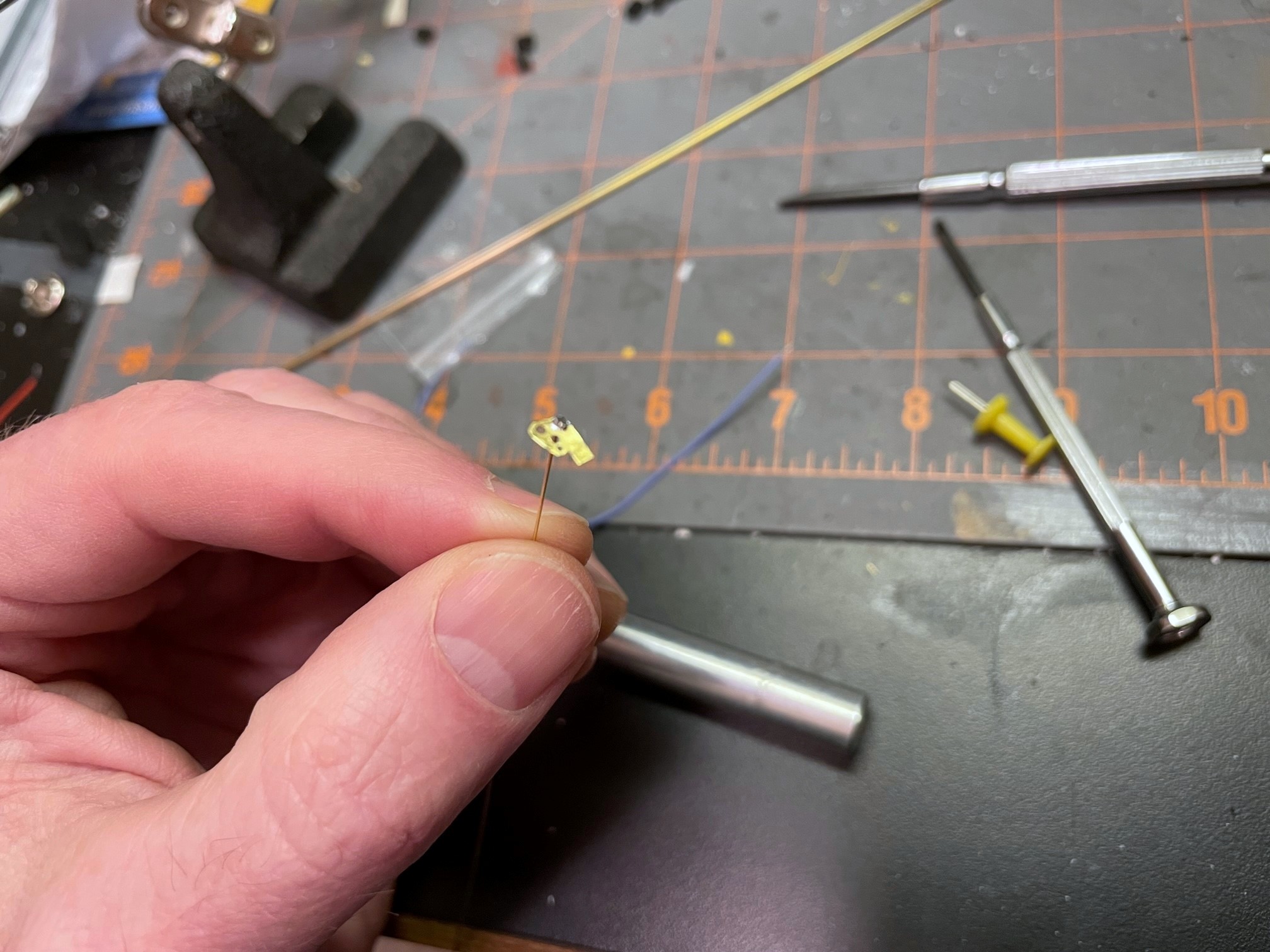
Faceplate and blade made from brass with the swivel wire soldered in place
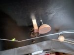
I made a drawing of the blade and faceplate with the lights, sized it down to HO scale, and printed it on sticker paper. After sticking it to a sheet of .005″ brass, I was able to drill holes for the lights, swivel and actuating arm and then cut it out with scissors. After cleaning it up with a file, I bent a piece of .015″ brass wire, inserted it through the swivel hole, and soldered it to the faceplate. I drilled a hole for the wire through a piece of 1/16″ brass tubing for the base. I wanted to use fiber optics for the lights, so I soldered a 1/16″ long piece of tube to the tall tube angling up to where the light would be to hold the fiber optic strand. I painted the faceplate and tubing black, then made lenses by melting the end of a piece of fiber optic into a mushroom shape holding it near a soldering iron. A little red for the blade and a white sticker stripe and the faceplate was complete.
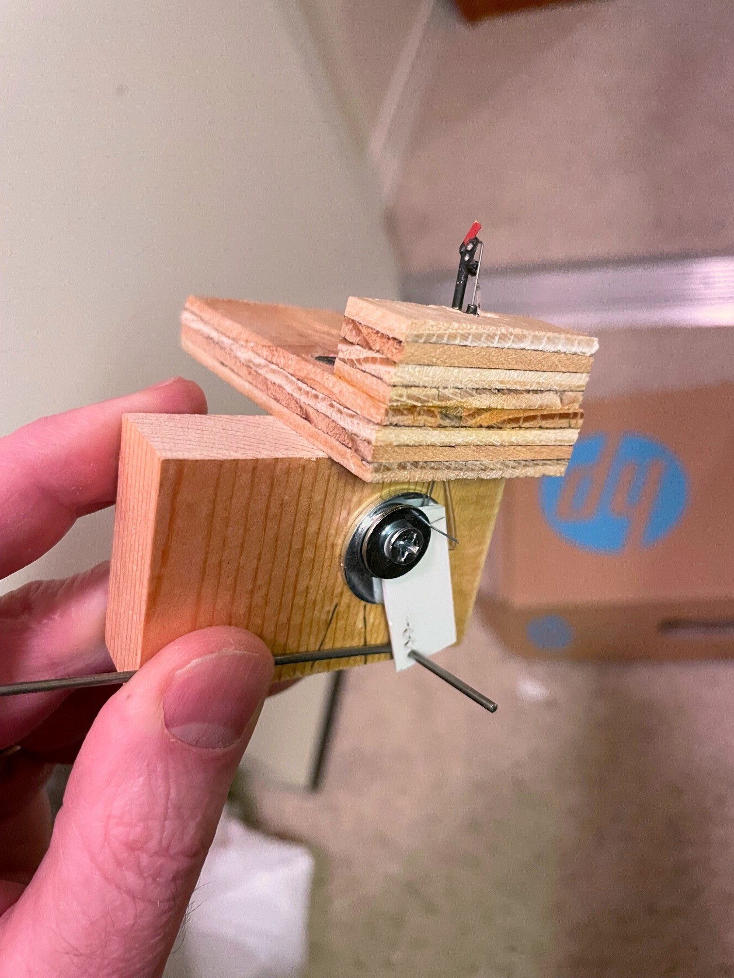
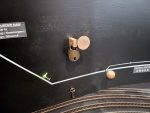
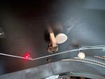
Completed dwarf semaphore model and lever mechanism
I mounted the base post in a piece of plywood and drilled a hole for a second piece of 1/16″ brass tube underneath the blade for the actuator arm. After inserting the faceplate and securing it with a bend on the back side of the tube, I had a faceplate that swiveled freely. A piece of .012″ steel music wire bent at a 90 degree angle at the end was inserted into the blade and the tube for the actuating arm. On the bottom, I made a lever for the actuator that raised the actuator just slightly while allowing for significant travel for the longer actuating rod connected to the fascia. I filed the end of a fiber optic strand so it would be parallel to the faceplate and inserted it into the little brass holder and through a hole in the base. A little silver paint for the post, and the tiny dwarf semaphore was complete!
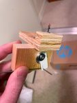
One of the things I wanted to model was the use of switch locks. I found some Miniature Locks on Amazon that suit this purpose perfectly! I decided to use a slide-switch mechanism like I use for all my switch controls, but I needed a longer slide to enable the lock to go in front of and behind the control knob to “lock” it into either position. I found some old three-position slide switches on eBay that did the trick! The slide switch serves two purposes–it “snaps” into position to hold the control and semaphore securely in position, and it allows for the routing of power to LEDs, in this case some bi-color red and green LEDs that change color when the polarity is reversed, something easy to do with a slide switch. After mounting the switch to the layout using a piece of 1×4″ board, I drilled two holes in the slide handle and used .o62″ steel wire to connect the slide to the lever under the semaphore and a separate rod through the fascia for the control knob, a 1/2 ball piece of wood.
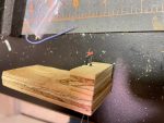
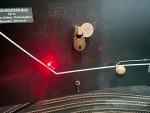
Semaphore control in the “stop” position showing the red fascia indicator and lock
For the lock mechanism, I used a bar of 1/4″ x 1/2″ basswood with a hole drilled for the lock and inserted it through a hole in the fascia and benchwork adjacent to and just touching the control knob. The hole sits just ahead of the control knob when it’s pressed in and just behind it when pulled out. I also connected two LEDs to the slide switch and a 12V DC power supply. One LED is mounted behind and just through the fascia to serve as an easy indicator for the full-size operators. The second was inserted into a hole drilled in the semaphore base where it can shine into the fiber optic strand.
The result is a semaphore with working lights, blade and a switch lock. While the dwarf semaphore sits about 3′ from the aisle and is tough to see, it is pretty cool to have an operating model and a tiny little red or green glow that matches the indicator on the fascia. Now the operators on the St Charles Branch, just like their real-world counterparts, have to stop at the semaphore, unlock the lever, change the indication, and re-lock the lever before proceeding up the branch (and do the reverse on the way back). While I’m not sadistic enough to make operators lock and unlock every switch they need to throw, working with switch locks a couple times during a session is one more step toward replicating the actions required on the real thing, and it adds a little prototypical time to the work required. Oh, and it helps protect trains without a dispatcher which is pretty useful.
[Note: since I first published this post, I decided to reverse my control mechanism so “proceed” is pulled out and “stop” is pushed in. It just required me to reverse the lever used to lift the arm. I figured having the crew move the lock to the front of the pull knob where it’s more obvious makes more sense.]
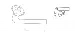
My PowerPoint drawings of semaphore blades and their HO scale counterparts
Faceplate and blade made from brass with the swivel wire soldered in place
Close-up of the mostly complete dwarf semaphore made from brass and fiber optics
Completed dwarf semaphore model and lever mechanism
The three-way slide switch wired up–the short leads are for the LEDs, the long leads connect to 12V DC
The internal guts of the control mechanism showing the two control rods routed through the handle of a slide switch
Two holes in the fascia, one for the control rod and one for the locking bar
Finished dwarf semaphore in the “stop” position–note the red light
The Black Mountain Local stops to reset the dwarf semaphore now that their work is complete
HO scale dwarf semaphore in the “stop” position
HO scale dwarf semaphore in the “proceed” position
Semaphore control in the “proceed” position showing the green fascia indicator and lock
Semaphore control in the “proceed” position showing the green fascia indicator and lock
Semaphore control in the “stop” position showing the red fascia indicator and lock
Semaphore control in the “stop” position showing the red fascia indicator and lock
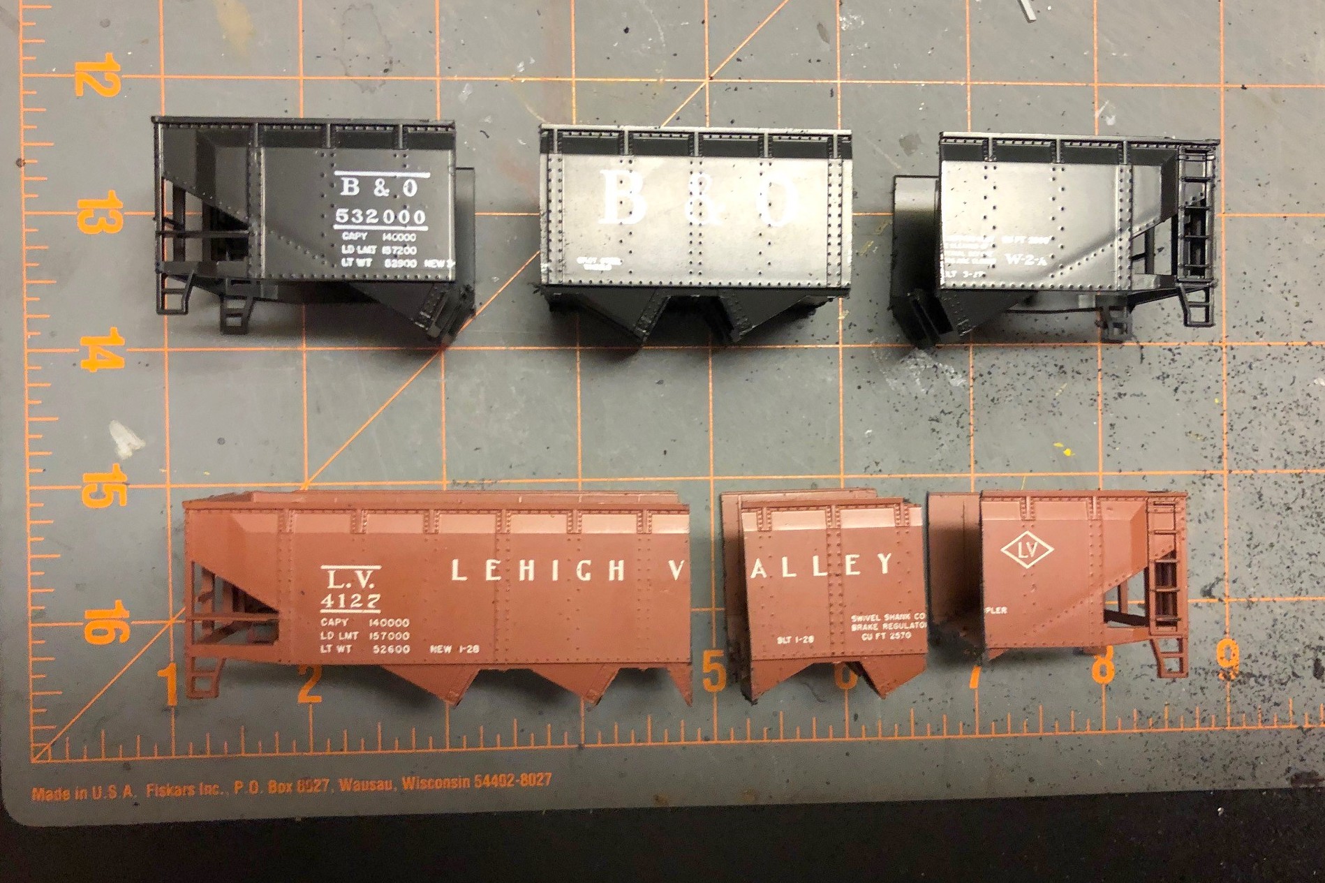
I’d had my eye on this project since the first time I saw a picture of one of these cars online. There were two challenges that held me back. First, no one made the right decals. Secondly, no one makes this car, so it would be a pretty major kitbash. It’ sat on the “someday” list until K4 Decals produced a set of good looking decals. The main excuse was now out-the-window, so I had to bite the bullet and figure out how to kitbash the car. The challenge is the shallower and steeper offset angles–they’re very distinctive and different from the angles on common twin hoppers like the old Athearn and newer Atlas models. The only thing that looked close were the angles on the old Athearn blue box quad hopper. I had one sitting on the shelf, so I took a closer look. It turns out the angles are perfect, as are the rivet strips and rivet patterns along the ribs. So, how to turn a quad hopper into a twin.
Cutting down a quad hopper to make a twin sounds pretty straightforward. If you don’t care about having an extra rivet strip, it is! Of course, I had to care… sigh. There’s an extra rib between the rivet strips on the twin compared to the quad, so I had to figure out how to get the extra rib in there. Turns out, there’s just no way to do it with a single shell (or I wasn’t smart enough to figure it out), but it was possible using two shells–2 quad shells to make a 1 twin… makes sense. I guess technically I could make 2 twins with 3 shells, so I did keep the extra pieces in case the bug strikes again.
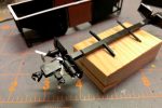
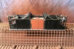
2. Cut hopper bodies
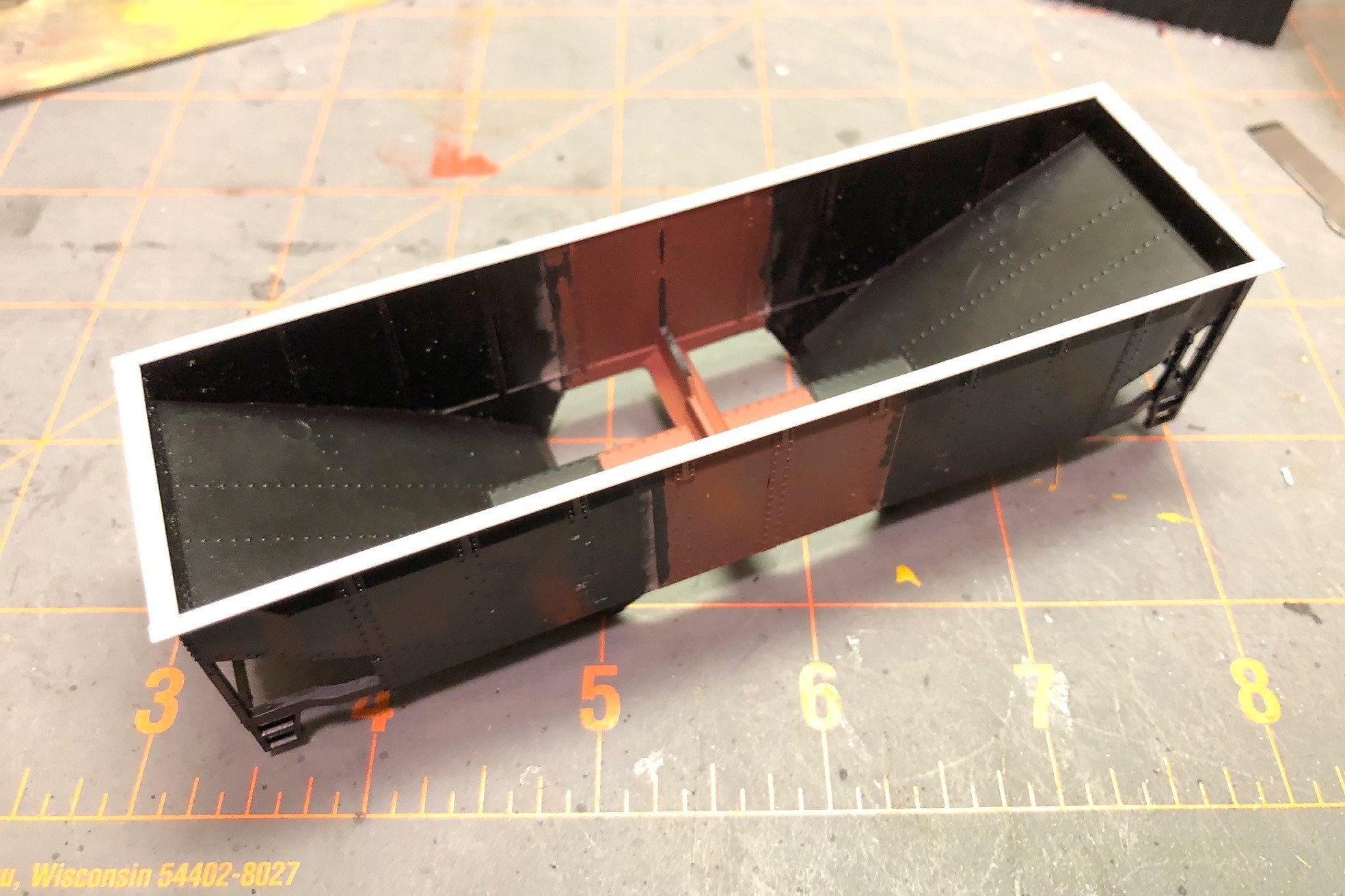
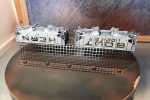
Picture 1 in the gallery shows the two original shells, and you can make out the pencil lines where the cuts need to be. I chose a spot between rivets to give myself a chance of saving the rivet detail in the putty and sanding step later. Using a razor saw, I cut each shell into three pieces as seen in picture 2 with the black hopper providing the ends and the red hopper providing the center. After cleaning the bays off what would become the center, I glued the ends to the new center piece as shown in picture 3. This step is the most critical of the whole project, and it took some filing to get everything square. I used plastic model cement to give myself time to line up the pieces–it’s crucial to get the sides aligned so they’re “level” across the gap. A gap is easy to fill and sand flat, but only if the sides are even with one another.
Once this new shell had dried thoroughly, I removed the top chord. The top chord on the original model is pretty chunky, and it would be easier to add a new one across the gap than try to fill every gap on top perfectly. It was pretty simple using a No 11 X-Acto blade swiped repeatedly under the top chord resulting in the shell seen in picture 4. Next, I filled the gaps with modeler’s putty. Using a combination of the back of an X-Acto blade and fine sandpaper, I was able to get the joint pretty smooth, and I was careful to stay away from the rivets as you can see in picture 5. This was also a good time to remove all the molded-on grabs with a combination of nippers and X-Acto blades. I found the corner posts and ladder posts to be really thick, so I whittled them down a little on the back side with an X-Acto. I also trimmed the top of the bottom sill near the ends to make it a consistent thickness instead of a taper like the model.
7. New styrene top chord
Next I worked on the center sill and undersides. First I cut the center out of a single underbody to shorten it to the right length and joined the ends together with glue. After it set, I used a large X-Acto chisel blade to remove some the material as shown in picture 6. I left a little strip to hold the hopper doors on. Next, I added a new top chord to the shell. I didn’t have the bag to verify, but I believe I used Evergreen HO scale 2×6 for the sides and 2×8 for the end to get to picture 7. I added four corner caps made from .010″ sheet styrene and rounded them on the top and on the corner after they dried using a file. Moving back to the underbody, I removed the existing mounting “blobs” for the brake gear, and in their place, I added angles from the bolster area to the corners using strip styrene (this was a pain, but I found if I cut them to the approximate shape, glued them with plastic cement, then press fit the underbody onto the shell and maneuvered the angles into position while the glue was still wet (I didn’t glue the underbody to the shell yet). When the angles had set, I added the brake parts including some brass wire for piping and a bracket for the reservoir made from sheet styrene as shown in picture 8.
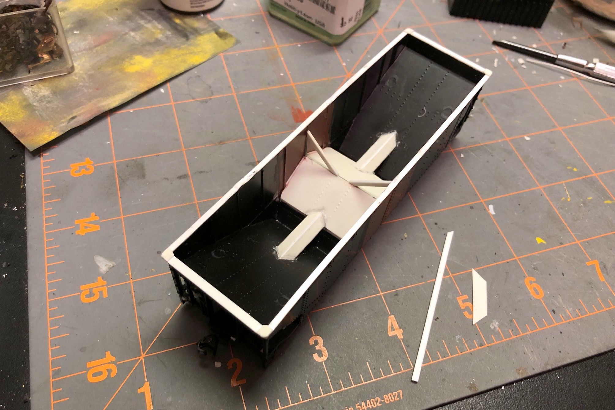
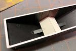
10. Finished interior
The interior of the car was challenging. I went ahead and glued the underbody and doors in place first, then added some styrene square rod above the doors to get it even with the model’s center sill piece. The new center slope sheets were cut from a single piece of styrene, and I used a pounce wheel to put some rivet lines into it to match the end slope sheets. Because of the ribs, the new slope sheet didn’t quite reach the sides, so I used bits of styrene to fill in the gap between ribs as seen in picture 9. Next came the not-so-fun part of turning the flat center sill ridge inside the car into a tapered one. I don’t have interior photos of one of these cars, but I can’t imagine using a flat top when you want the coal to exit the car. This step was not fun. Not one bit. Lot’s of measuring, cutting, folding, and taking back out and cutting again. My pieces ended up being too wide, but I just glued them on, let them set, then trimmed them to the width of the ridge in the shell with an X-Acto blade. Some styrene strips to make the angle braces and the interior was complete as seen in picture 10.
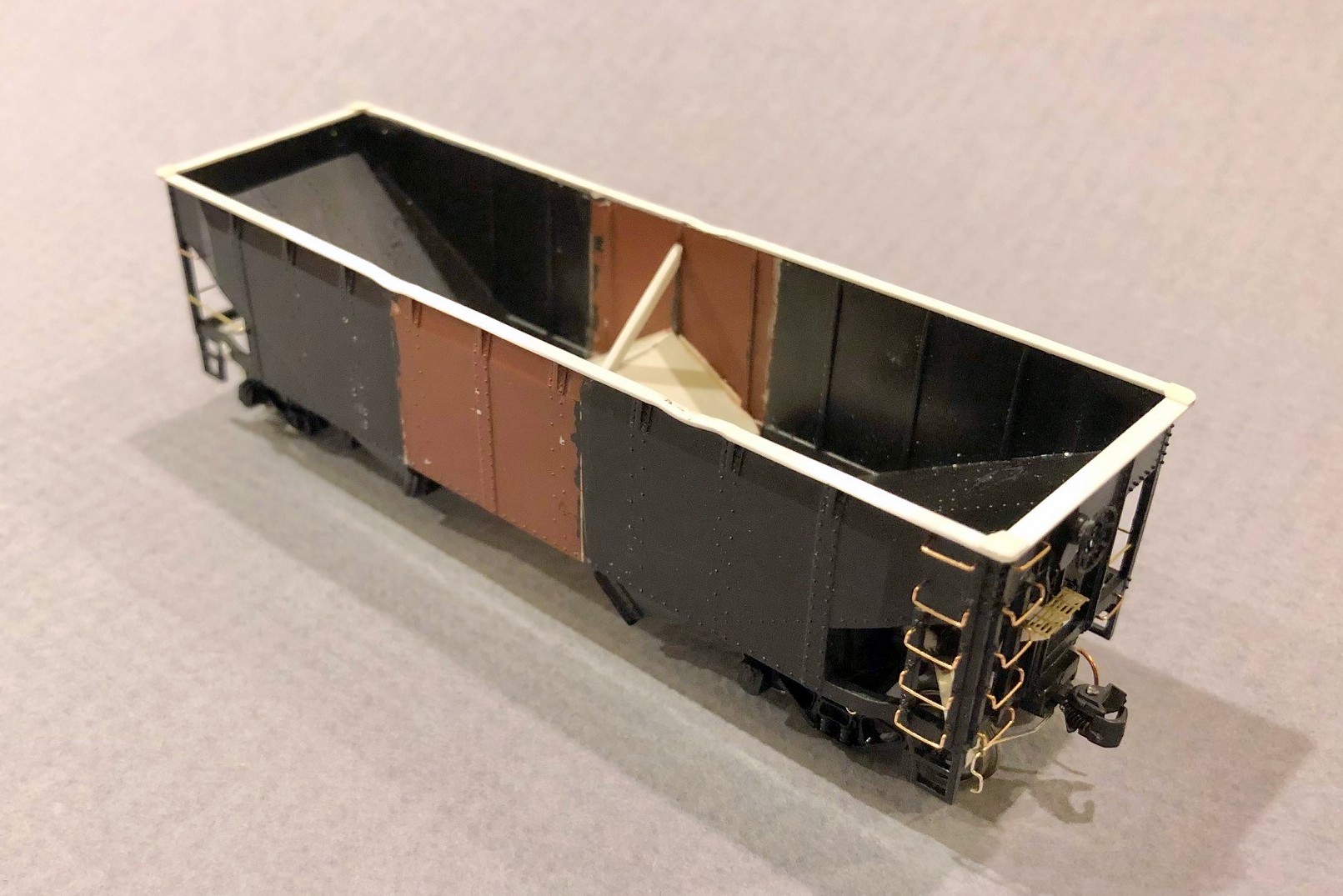
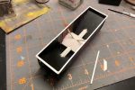
11. Final details added
Now I was ready for all the little details that you can see in picture 11. I drilled holes and installed all the grabs, making the long grabs on the non-ladder side from brass wire. I added coupler cut bars to a bracket made from styrene and an eye bolt. I made tow loops from brass wire, and I made a new brake platform from bits of styrene and some brass Apex roof walk material. I added the brake line along one side using brass wire and eye bolts. I added some tack boards from styrene on the bottom sill. I added train line hoses made from copper wire from old Cat 5 cable glued between two styrene angle bits (makes for an indestructible train line). A kept the molded on steps as I needed them to be durable for layout handling, but I used an X-Acto blade to shave them down a bit in the back to thin them out. Finally, I added a little buckling to the top chord using a 100W lightbulb held to the styrene for a few seconds and then pushed down using the handle of an X-Acto knife (be careful, the styrene melts really quickly). It was finally ready for paint (picture 12).
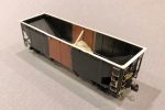
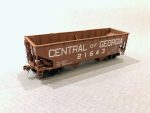
16. Final hopper – interior weathering
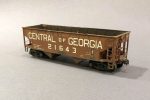
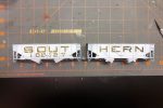
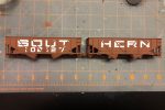
I first sprayed everything black, then gave it a couple coats of “burnt sienna” for the boxcar red. Because the paint was very flat, I sprayed it with a couple coats of Testors Glosscoat (rattle can) to prep it for decals. The K4 decals worked really well and had just about everything needed with the exception of an ACI label I stole from a Microscale data set. The K4 set looks like it’s designed for a 33′ car, and this prototype is a 34′ car. I ended up cutting the road name into “CENTRAL,” “OF” and “GEORGIA.” I place the end lettering first and then centered the “OF” between them, a little more spaced out than the decal sheet. I used about 800 applications of Micro Sol and Micro Set and pushed the decal firmly onto the body using a damp paper towel until everything was nice and snug over the rivets and on the body as seen in picture 13.
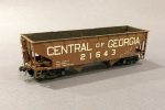
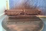
Weathering was a three step process. First, I dry brushed a little dark rust color both inside the hopper and in a few spots on the outside using a picture of this specific car as a guide. Next I gave it a couple of washes with very thinned black and then tan paint, wiping it off down the car (like rain streaks). Finally, I airbrushed some black inside the hopper and underneath followed by a couple coats of tan, hitting the trucks and hopper bays harder than the body to get the final model shown in pictures 14-17.
I’m very happy with how this project turned out, but I’m also very happy I don’t need a fleet of these cars. Many will look at this car on the layout as “just another offset hopper,” but I’ll always know the extra work that went into building a more accurate model of a neat prototype.
1. The two Athearn quad shells with pencil lines where the cuts will be made
Interstate hand-me-down hopper in transloader service
Added another hopper to the roster today. This car is one of the hand-me-down hoppers given to the Interstate in the early ’60s when the INT was under Southern ownership but still operating independently. The independence didn’t stop the Southern from specifying a Southern-inspired paint scheme. This model started life as an Athearn blue box model–it was a hand-me-down from an old friend and mentor who got me into model railroading as a kid, so the body of this car must be 40 years old! The toughest part of this model was modifying the angular peaked ends to the oval version seen here. The cars in this series were a hodgepodge with various ends, so photos are helpful. Other details include DA steps, tichy grabs, and some homemade tow loops. The decals came from K4 Decals, and the unit received moderately heavy weathering to reflect its age and status as an end-of-life car.
After 1965 when the Southern consolidated its operations at the Interstate’s Andover Yard, most of these cars spent the rest of their lives in captive service between the Interstate and St Charles area mines and the Westmoreland Transloader that was build on top of the Southern’s old yard in Appalachia, VA. These cars became known as “yellow balls” because many of them had a large yellow circle painted on the side. This is actually my first time actually applying a “yellow ball” to a model hopper, and it’s definitely something I’ll duplicate in the future as it makes these cars very distinctive!
Interstate hand-me-down hopper in transloader service
Interstate hand-me-down hopper in transloader service
Finished car with some light black and tan airbrushing on the sides, trucks and interior
The Southern Railway was definitely known for innovation, especially in the ’60s. They were one of the first railroads to use large numbers of 100T hoppers for moving coal. The Southern still had a large number of usable 50T cars, particularly war emergency rebuilds and ex-Interstate hoppers, so they permanently paired some of them into what they deemed 100T “articulated hoppers.” There was nothing fancy about it, they just removed the coupler cut levers from between the cars, put the brake ends of each car at the ends, and numbered them as a single car. The idea was it allowed 100 tons of coal to be moved in a single car shipment for a customer which gave these old cars a little more life in the 100T era. There were several paint schemes used on these cars include a red version with “SOUTHERN” on the left-hand car and the car number on the right-hand car. Some cars had a black version of this. The most striking and unique cars were those painted with giant lettering and “SOUT” on one car and “HERN” on the other–this is the car I wanted to model.
The base cars were easy enough. They’re essentially stock Proto 2000 War Emergency hoppers with a couple minor modifications. I trimmed the tow loops off the bottom, added small beveled strips of styrene under the outermost ribs, and used bent .012″ wire to fashion new side-mounted tow loops above the styrene strips. I also used dummy couplers on the “A” ends of the cars that I pulled out of an Accurail 50T AAR hopper kit–this will keep operators from inadvertently uncoupling the car on the layout. I only added coupler cut bars to the “B” ends like the prototype, and I added a scratchbuilt train line air hose to each end (piece of bent copper wire from old Cat 5 cable sandwiched between two styrene L-shapes).
Step 4. Apply the lettering masks to the car, cutting around the ribs
The tricky part of this model is the lettering. No one makes a lettering set that even comes close, so I would need to either make my own decals or somehow mask and paint the lettering–I opted for the latter technique. First, I had to draw up some artwork. I used my favorite graphics program, Microsoft PowerPoint, to create the lettering using large rectangles and quarter circles. Once it looked about right, I copied and pasted the lettering as an image (right click and picture icon) on a new sheet, then I was able to size it and print it with the letters 3′ tall in HO scale and the numbers 2′ tall. Then I covered the lettering with some Tamiya model masking tape and ran it through the printer again to get the ink onto the top of the tape. Warning: even after the ink dries, it still smears a bit, so I used another piece of plain masking tape to remove some of the ink, and I was careful not to get smudgy fingers on the car.
Speaking of the car, I airbrushed the sides white and let them dry overnight. Back to the lettering, I carefully peeled the tape off the paper and placed it on a clean cutting mat. Then I used a straightedge and Xacto blade to cut along all the straight edges. I freehanded the corners which was a bit more challenging. The angled ribs on this car required me to eyeball where the rib would go through the letter (I had a picture of an actual car), so for each rib I removed about 1/16″ of masking tape. Next, I peeled the letter mask off the cutting board and applied it lightly to the car, using a blade to lift and reposition it as needed. After all the lettering was in place, I used the round end of the Xacto handle to burnish the tape onto the sides securely.
Step 7. Carefully remove the masking using a sharp blade to get under the tape
Back to the painting booth, I first sprayed the cars with black as a dark primer and then gave them a couple coats of oxide red and let them dry for an hour. After the paint was dry, I carefully removed the tape from the sides using a blade and careful fingers to reveal the white lettering. I thought I was going to have a lot of touch-up to do, but the tape held up very well and left mostly clean edges. With all the tape off, I then used a brush and white paint to fill in the lettering gaps across the ribs. I sprayed it with some gloss coat and applied the capacity stencils and other small lettering from a Microscale data sheet using multiple liberal coats of decal solvent and decal setting solution. After letting the decals dry for a day, I hit the cars with another coat of gloss (the paint came out REALLY dull, so even with three coats of gloss it’s pretty dull).
For weathering, I first dry brushed a little light rust and dark rust onto the car, mostly on the inside to simulate a few years of wear with the paint just starting to wear through where the coal repeatedly tugs at it. Next I gave all surfaces of the car a couple coats of black wash (water with a dab of paint). I worked one set of sides at a time (one “SOUT” and one “HERN”) to ensure the weathering was consistent across cars, brushing on the wash, letting it sit for a couple minutes, then dabbing and streaking it off down the sides with a moist paper towel. I followed the black wash with a single wash of tan. The final weathering was some black airbrushing inside the hopper and along the bottom followed by some light tan airbrushing on the sides and trucks.
Finished 100T articulated hopper showing the huge “SOUT” and “HERN” lettering
I’m pretty happy with how this car turned out. It’s definitely unique and is bound to be a conversation piece on the layout. I can’t wait to watch the first operator trying to uncouple the dummy couplers so I can give them a little history lesson in Southern innovation!
Step 1. Print the artwork, cover with masking tape, and print again
Step 2. Paint the sides of the cars white
Step 3. Cut out the letters using a sharp blade and straightedge
Step 4. Apply the lettering masks to the car, cutting around the ribs
Step 5. Paint the car (I primed with black first)
Step 6. Let the paint dry
Step 7. Carefully remove the masking using a sharp blade to get under the tape
Step 8. Ensure all tape is removed
Step 9. Paint the white lettering onto the ribs using a brush
Step 10. Dry brush some rust–I dry brushed lightly on the sides and a little heavier inside, then I did a black wash and a tan wash
Step 11. Finished car with some light black and tan airbrushing on the sides, trucks and interior
Finished car showing the brake detail on the ends
Finished 100T articulated hopper showing the huge “SOUT” and “HERN” lettering
The next installment in the “heritage fleet” of hoppers is an original Norfolk Southern 70T car still in gray paint. The NS wasn’t acquired until 1974, so this represents a car most likely in “yellow ball” captive service to the Appalachia, VA transloader in the late ’70s.
Orginal NS 70T hopper that’s seen a bit of service
The model is a factory painted Bowser hopper with some detail upgrades. Because it will be a light gray hopper in a sea of black and brown, I figured it would catch the eye more than most cars, so it has a higher level of detail than most of my cars. I removed the molded-on grabs and replaced them with wire, upgraded the brake detail, and added coupler cut bars and a trainline. Weathering if primarily drybrushing for the rust spots. I’m pretty happy with how the inside turned out–it’s two colors of rust drybrushing (dark rust for most with light rust around the paint edges) and a little black airbrushing.
These heritage cars are a lot of fun! I’ll need at least one 55T fishbelly hopper in NS gray as well.
Rusty inside of an original NS hopper made from a Bowser model
Two Southern “heritage fleet” hoppers being spotted