Monthly Archives: February 2021

Laying Ties on Mayflower Branch

Mayflower Tipple and Ties
A close-up of the Mayflower Tipple mock-up with ties running underneath

Made some progress this week on the Mayflower Branch section of the layout. All the ties have been laid! This is a tedious but simple process made a lot easier by the outline of track left over from tracing flextrack onto my subroadbed for cutting. I just place the material (1/4″ door skin for me) on top of the layout, place thumbtacks in the holes of a piece of limber Atlas flex track, fasten the track down with the pins using turn radius templates and “eyeballing” the rest, then use a pencil to trace down both sides of the track. For marking switches, I leave a portion of the track fastened and move the loose section to trace the divergent track. After tracing, where the pencil marks diverge is the location for the turnout points and longer block ties. After the subroadbed is secured in place with risers, screws and glue, I’ve got a perfect template for the tracks on the layout for laying ties (more about making and laying ties below).

Ties for the Mayflower Branch
Overview of the Mayflower Branch section of the layout with the ties freshly installed (this one’s for you, Bill)

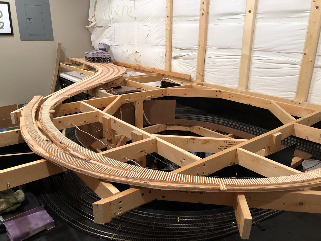
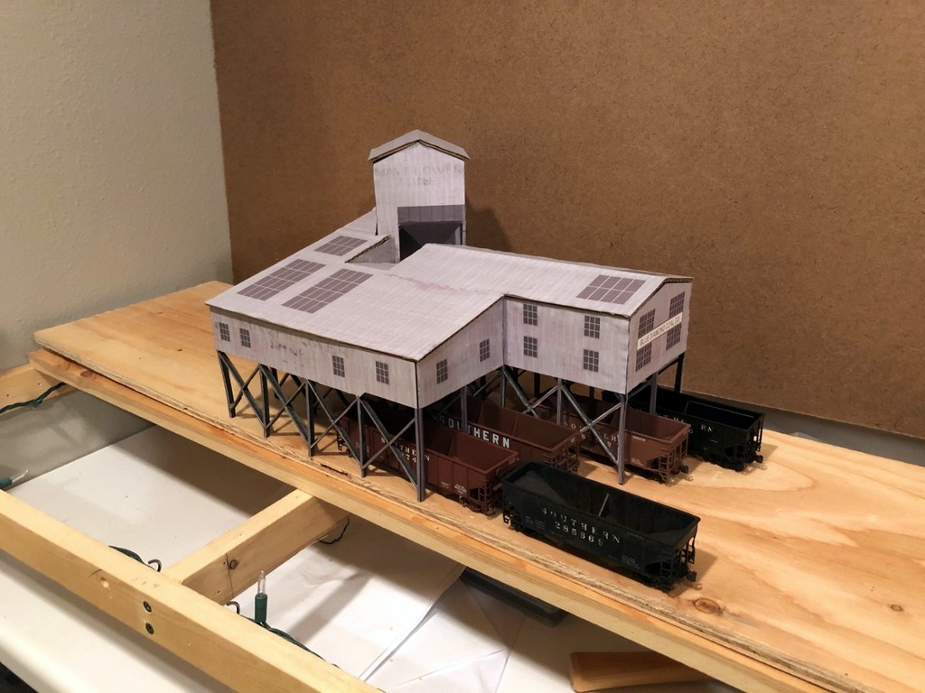
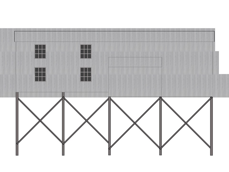
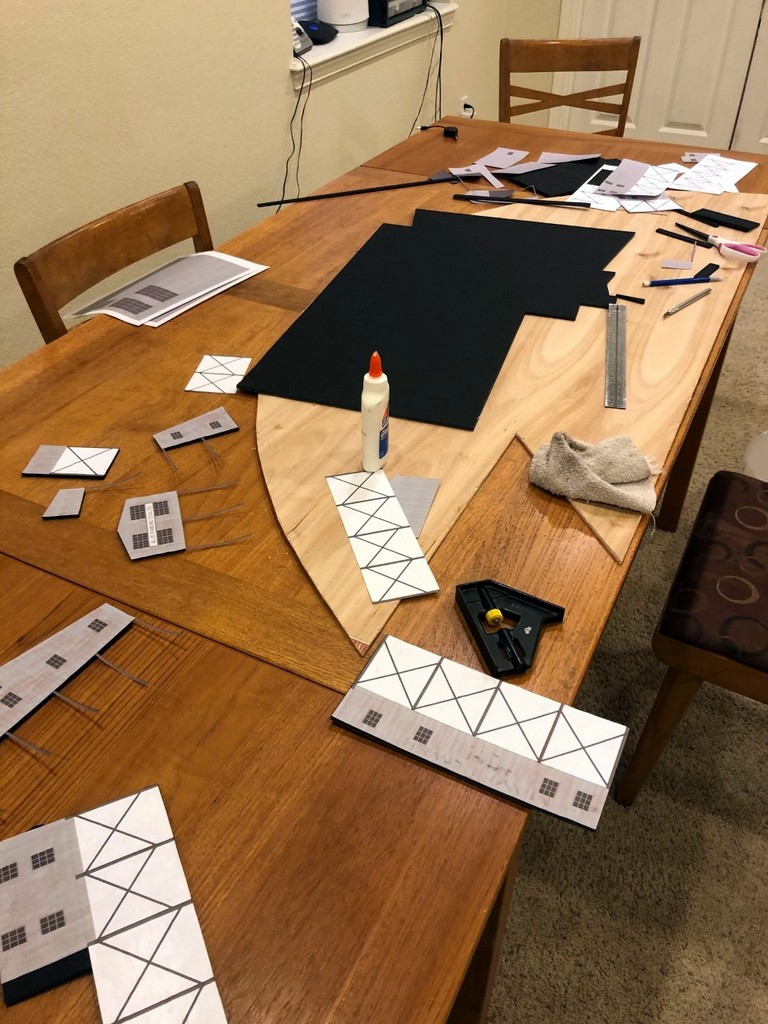
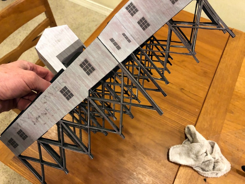
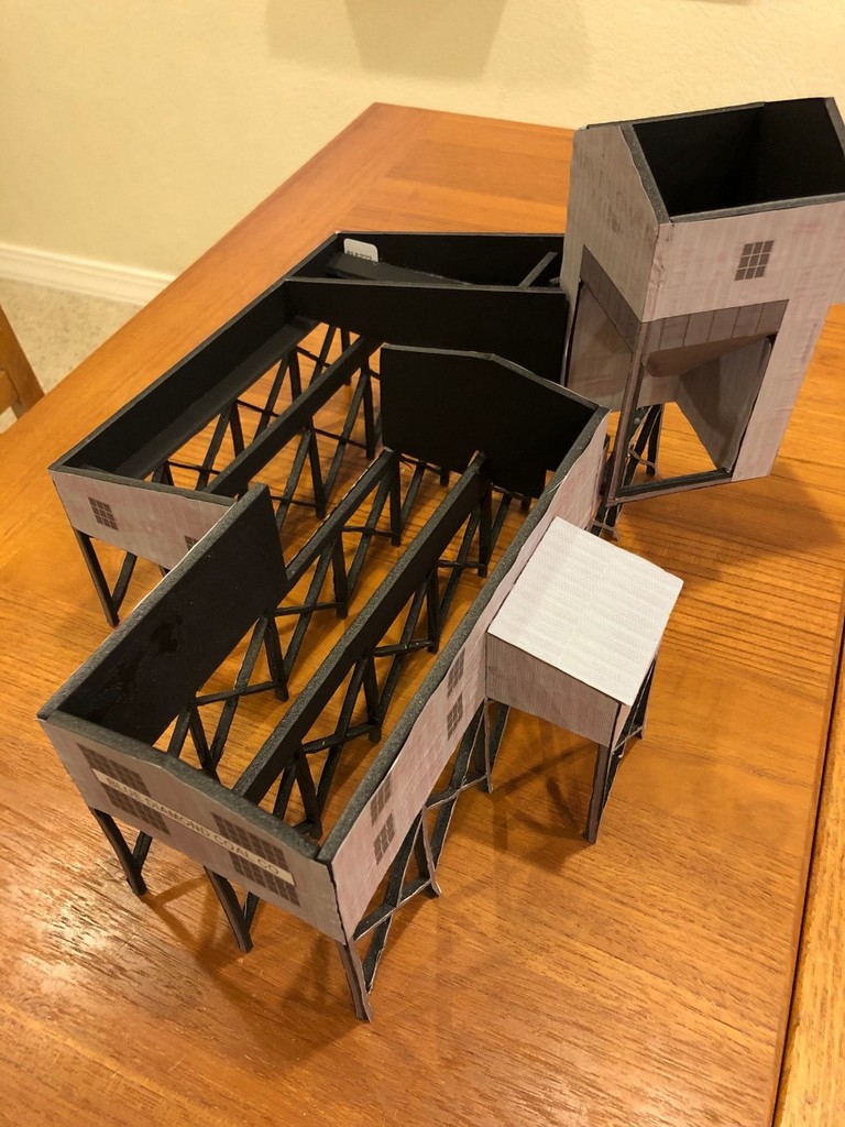
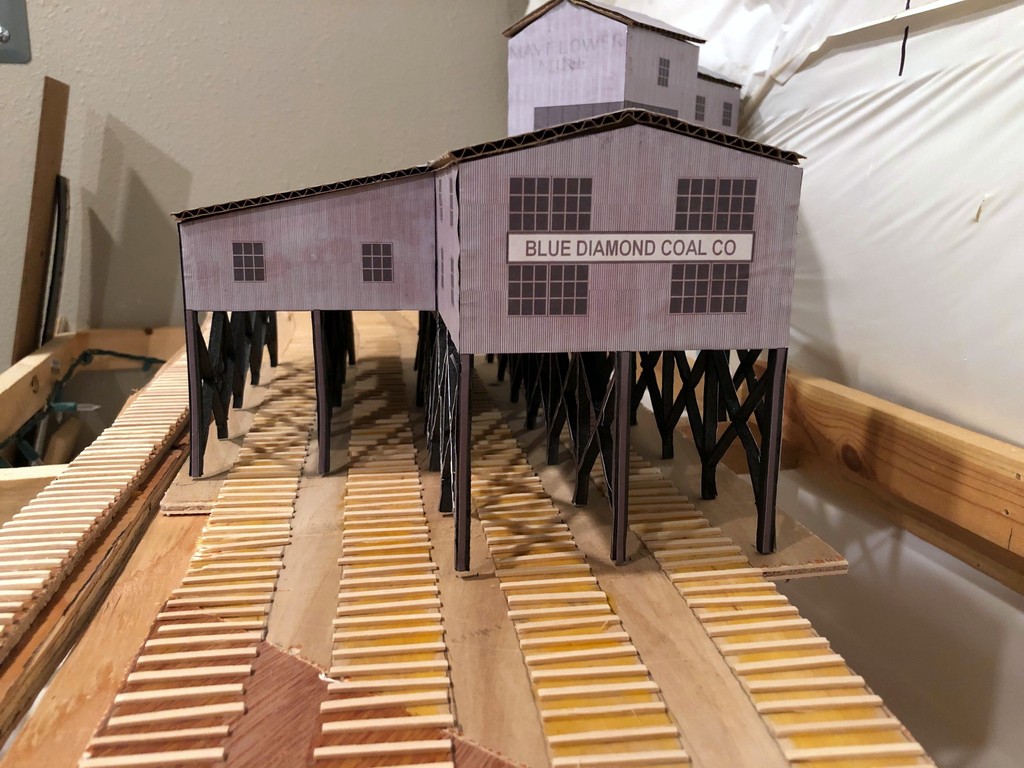
Now that all the ties are in place and I have the mock-up of the Mayflower Tipple, I can really start to visualize the entire scene. I’m really liking how the track snakes into the scene, and I think the gentle curve into the tipple will really look cool with strings of hoppers hanging out. You’ll also notice the tracks run into the wall–I didn’t have enough room to model the empty yard, just some space for empties above the tipple. This was an easy compromise to make for space because the empty yard at Mayflower was a stub-ended affair, so crews still had to run around and shove cuts of empty hoppers, just as they’ll need to do here. I can’t wait to get the rails down and operate that first mine run! There’s a lot of rail-laying between now and then, but it’s good to see it coming together.


Making Ties
My “workbench” for making ties–I cut strips from 1/16 and 3/32″ basswood to use for siding and mainline ties, respectively.

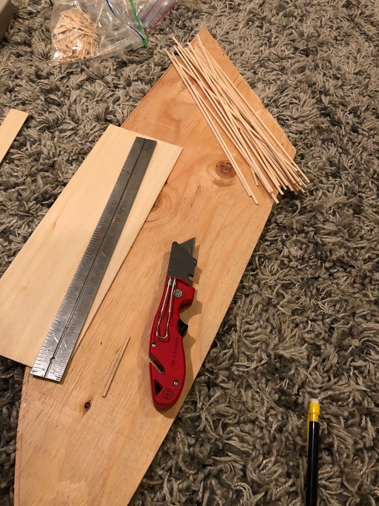
Making Ties. Rather than buy bags of ties, I cut my own from sheets of basswood, 1/16″ for siding ties and 3/32″ for mainline ties. It’s not that ties on the prototype were different heights, but using different height ties on the layout keeps siding tracks a little lower than the main (very prototypical). I use a “spacer tie” to line up a metal straightedge the proper distance from the edge of the basswood board, then cut it with a couple strokes of a sharp utility blade. Most sheets come in 2′ length, and I’ve found it easier to cut it to 1′ length first so I don’t have to move the straightedge in the middle of a cut. With a bunch of sticks in hand, I then use a Northwest Shore Line “Chopper II” (amazing tool) and a scale rule to cut the ties in .5′ increments from a scale 8.5′ to 16.5′ with a separate, well-marked ziploc baggie for each size and length. Standard ties are 8.5′, and switches require a few of each longer size as you progress up the switch with 16′ ties for block ties at the points.


Ties tell a story
Ties tell a story about the type of track you’re modeling from mainline to well-used siding

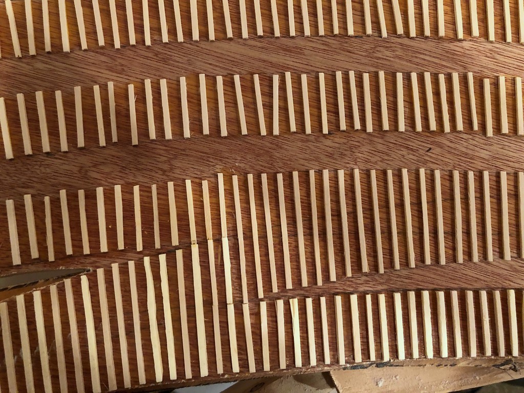
Laying Ties. Laying ties is a simple matter of putting down some wood glue on the subroadbed and placing them. I work in sections of about 8-12″ at a time to make sure the glue doesn’t dry before the tie gets there. Ties tell a story about the kind of track you’re modeling, and it’s one of the reasons I love hand-laying track. Mainline track should be in good working order with closely spaced ties perpendicular to the rails and just a little side-to-side variation. Well kept sidings are similar but with perhaps a bit wider spacing between ties. For old, well-used sidings like you’d see at coal tipples, I’m pretty haphazard with my ties, allowing some of them to kink off perpendicular and lots of variation in spacing and alignment from side-to-side. It looks absolutely disgusting before the rails go on, but the effect is more subtle once the ties are stained and the rails are in place. I love disgusting looking track that still runs well, so I can be pretty aggressively messy when laying siding ties!

Mayflower Tipple Mock-Up

Mayflower Tipple Mock-Up
The final tipple mock-up in place on the layout showing its size relative to the benchwork and hoppers

I’ve finally started laying subroadbed onto the main level of the layout, and I’ve chosen the section between Baker and Mayflower as my first scene (see track plan). Mayflower is the first of four large tipples on the layout, so to make sure I’ve got proportions and track spacing right in the plan, I decided to build an HO scale mock-up from foam core and cardboard first. I’ll just warn you, this is not a time-saving process, but it certainly helps you visualize a scene and make adjustments before building more permanent structures and track. Because this was the first and the only large tipple on the lower deck where vertical spacing would be important, I decided it was worth the effort.

Mayflower Tipple Pics
This is all of the photographic material I had from which to draw and build the Mayflower Tipple

Step 1 – Research. I’ve made a commitment to modeling the tipples as closely as possible (rule: no Walthers New River Mine allowed–it’s not a bad kit; it’s just over-used and too recognizable). The trouble is this area is not well documented by photos, so there’s a lot of guesswork and extrapolation involved. The first resource I had was a track chart that showed four tracks under the tipple, a medium-sized operation. Next, I found an aerial photo from the 1960s that showed the basic footprint of the tipple and the distinctive portion of the tipple connecting the tipple to the mine that sits 45 degrees to the tracks. Finally, I found a single grainy photo of the front of the tipple and a painting of it from a post card that someone had posted to Pinterest. With these resources, I had enough to rough-out a drawing.

Step 2 – “Scale” Drawing. Regardless of whether or not I’m building a mock-up or the final model, I need some sort of scale drawing to build from, and for tipples that were one-of-a-kind, actual drawings are very rare. I use the word “scale” here loosely because none of the research offered any clear dimensions. Still, distances between tracks and height above hoppers can be estimated, so I did my best. To make the drawing, I used my favorite drawing program, MS PowerPoint. No, PowerPoint isn’t designed for this, but it’s easy to use, and you can draw lines to specific dimensions and angles. I would work on one side, matching it as best I could to the photos. Then I’d copy relevant bits from the one side to use as size references for the next side until all the parts were drawn. Some sides were longer than a piece of paper, so I drew these as two separate drawings I could glue together later. The tricky part was the photo and postcard showed two different time periods for the tipple. The photo showed a section added to the front over two tracks, so I had to figure out how this might have worked in concert with the tipple represented in the postcard.

Mayflower Tipple Drawing 1
Line drawing of the front of the tipple showing the 2″ track spacing and profile

I decided to draw windows and corrugated metal siding on it as well. This was a simple matter of making a generic window and copy/paste it in place. The siding was just a texture I found online and copied into scale sheets to place behind the drawing (use the “send to back” function on right click). When everything looked decent, I printed it out.

Step 3 – Building the Mock-Up. For material, I used black-on-black 1/4″ foam core picked up at the local big box hobby store. It’s easy to cut and work with and has enough rigidity to make a durable structure. I cut out pieces of the drawing and then glued them to the foam core using normal white glue. Where I have a corner, I needed to pick one wall to recess the width of the foam core so they won’t overlap (i.e., when gluing the drawing would overhang the foam core by one foam core width). As you can see from pictures, the glue caused a little discoloration and warping of the paper, but hey, it’s a mock-up. Next I cut along the edges using a metal ruler and X-Acto blade. The trickest part by far was cutting the intricate frames of the leg pieces (5 total). A mock-up doesn’t really require this level of detail, but I decided it was important enough to judging the look of the tipple that I spent an extra 3 hours or so cutting these out. The glue and paper caused some of the sides to bow a little, so for these I cut out 1/2″ wide strips of foam core to attach perpendicular along the back and bring them back into shape and provide lateral strength. This required laying a heavy book on top while it dried, but it worked well.

Mayflower Tipple Mock-Up Assembly
Tipple mock-up in progress–I worked one joint at a time

With the pieces cut out and strengthened, I started gluing them together. I worked on one corner at a time and used little pieces of square foam core to keep the corners square. I added structural pieces of foam core wherever needed to keep things sturdy. Again, the trick was to work one joint at a time (no more than two) instead of trying to build it all at once. The glue dried sufficiently in about 30 min, so I’d just come by every 30-60 min and glue another side on. Finally, I made the roof out of corrugated cardboard salvaged from a box–it’s a little thinner than the foam core but still has sufficient rigidity. After test fitting the roof pieces and making adjustments with the blade, I glued on the roof pieces–this is tricky because you have to worry about a lot of edges at once.

Step 4 – Evaluating the Scene. With the Mayflower Tipple mock-up complete, I could now mock-up the scene on the layout and see where the tracks would go, how tight the spacing would be for hoppers (adequate), how far I could bring it out or push it back in the scene, how much space I would have with the upper deck, etc. As it turns out, the tipple fits perfectly and doesn’t need any adjustment, but it would be easy to make cuts and repairs to the mock-up to try different things that would be a lot tougher to do on a final model. Any changes would simply be added to the drawing to use for the final model.

Conclusion. While I could have been halfway done with a permanent model in the time I built this mock-up, I now have the confidence in my drawing and in the scene to build the final model. Besides, it will be a while before construction on the upper deck in this area will be complete enough to install a permanent model, so in the meantime, the mock-up will give me and other crew members a good stand-in to enhance operations that I don’t mind getting a little roughed up. Beats having to use your imagination when switching out empty and loaded hoppers!