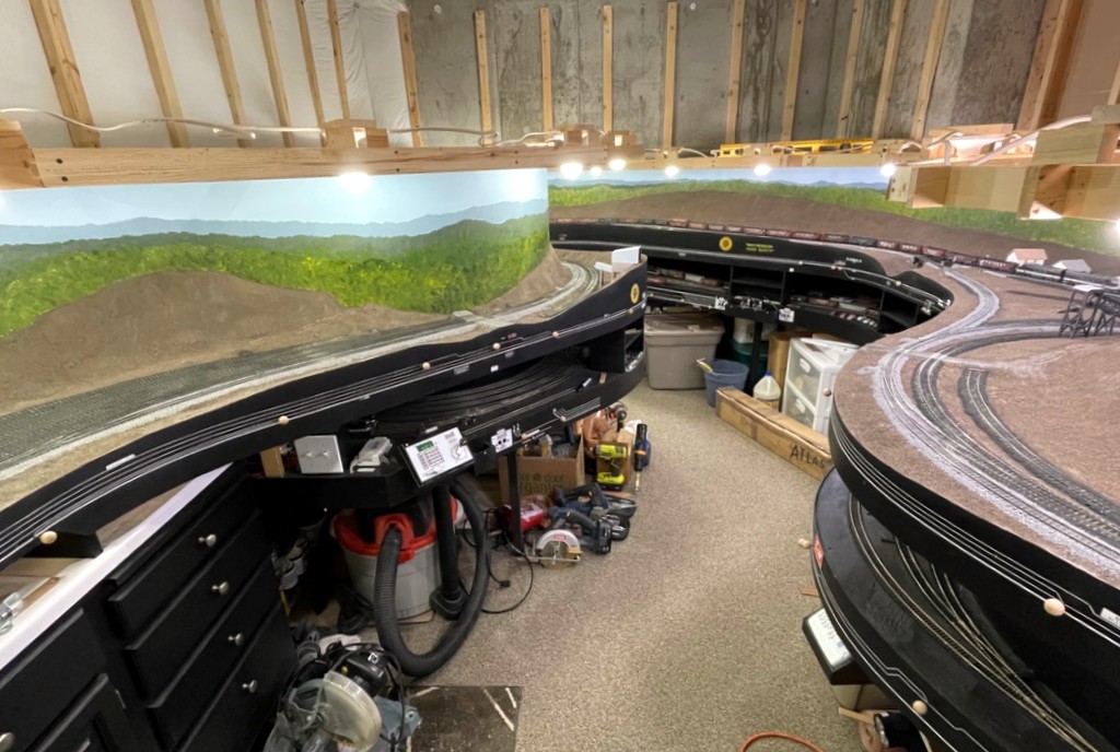
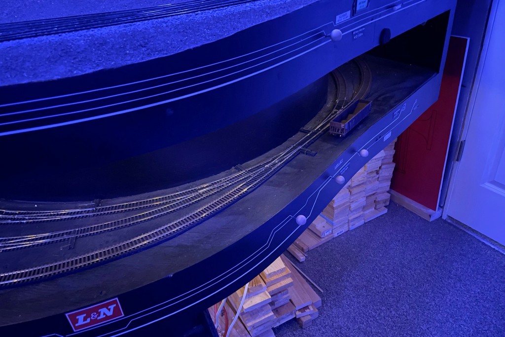
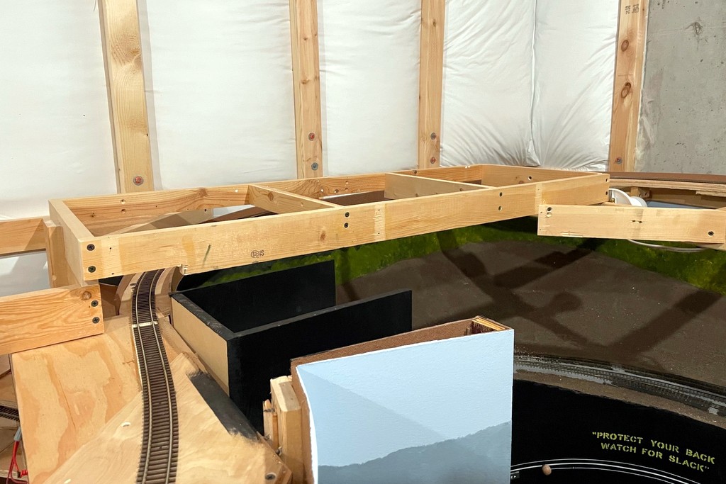
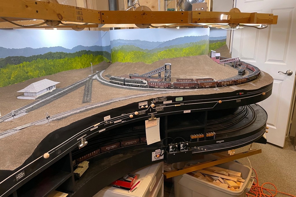
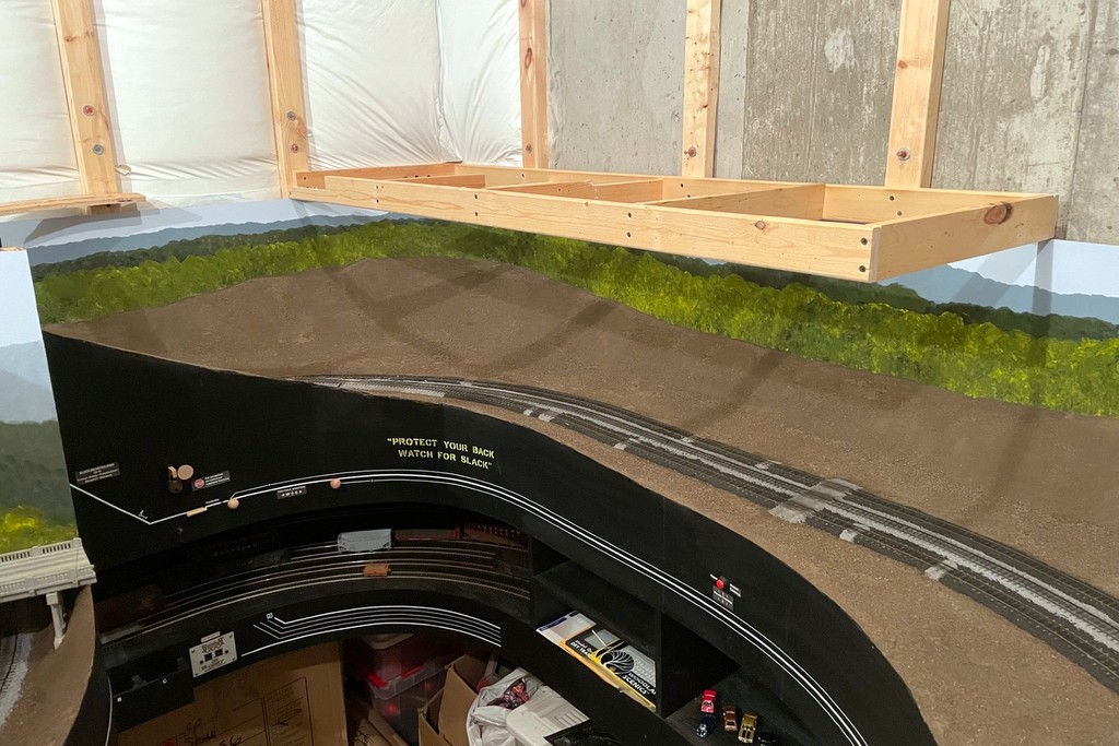
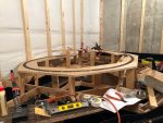
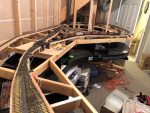
Upper level benchwork showing the new lighting fixtures for the lower level
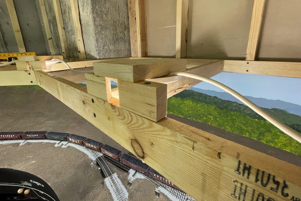
A few weeks ago I posted about installing the first lights on the layout. I’m using multi-color, dimmable LED smart bulbs, and one of the surprises I faced was the limited angle of “light throw” from the LEDs compared to incandescent bulbs when mounted horizontally like they were on my last layout. I experimented with ways to get the bulbs to sit vertically and came up with this style of lighting fixture. It’s a simple setup with two blocks of 1×2″ lumber about 3″ long and a piece of 1×4″ lumber about 5″ long cantilevered off the top. The 1×2″ pieces are cut 45 degrees on one end which allows the plastic fixture to snuggle into the blocks above the benchwork edge to get the lightbulb as close to the layout edge as practical. The globe area of the bulb now sticks out about 1″ below the benchwork which does wonders for eliminating awkward shadows from the benchwork (this 1″ will be covered by fascia eventually so you’re not staring at bright bulbs while running trains). The major drawback to this method is it requires a lot of vertical space, so I’m having to adjust my track elevations on the upper deck upward about 1″, and I’m having to strategically space my lights to avoid areas where creeks and valleys will run all the way to the fascia.
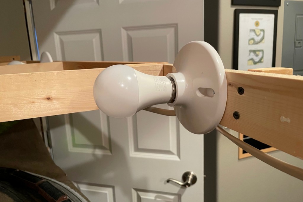
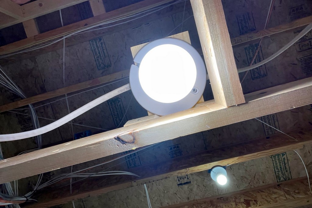
The original horizontal orientation for the simple plastic screw-in basesThe new lighting fixture that casts more light downwardView of the new fixtures from below
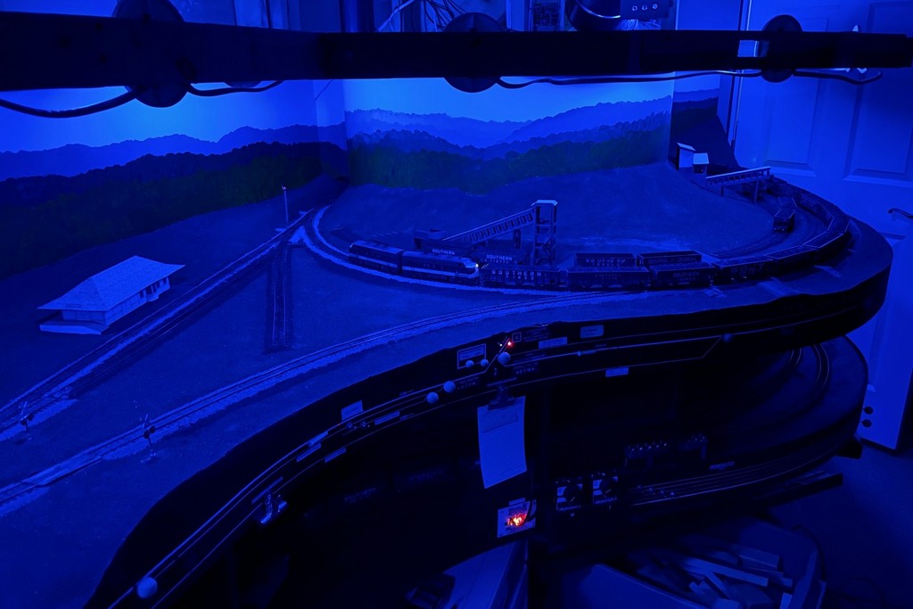
Despite this drawback, I’m REALLY happy with the lighting this provides and the flexibility inherent in the multi-color smart bulbs! Like my last layout, I’m placing them about 24″ apart to get good lighting into all the spaces. They’re 60W equivalent bulbs, so when they’re on full power, it’s really bright… too bright. I find dimming them to about 65% is just about right, but the beauty is I can change this at any time using my phone app that controls them. I can also adjust the light temperature anywhere between 2700-6500K to get a good “daylight” feel, and I’ve found a nice blue/cyan color I can turn down to 1% brightness to get a moonlight feel and still be able to see what’s going on. To counteract some of the shadowing on the extreme aisle edge of the lower deck, I installed the same LED smart bulbs in my four overhead fixtures–they can be tuned to the same color as the layout lights. I also installed a smart dimming outlet I can run from the same app that controls the strings of cheap LED soft white Christmas lights under the layout that illuminate the staging yards and aisles.
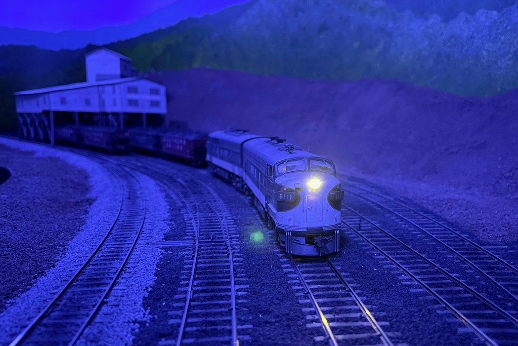
The new LED layout lights can be used to simulate a wide range of lighting conditions including “moonlit night”A pair of F-units are working late into the night to finish up the work of the Black Mountain Local
I’m running the lighting with three groupings in the app, one for “main” (all LED smart bulbs), one for “overheads” (just the four overhead lights), and one for “aisles.” This setup gives me the ability to control the intensity and color going to the layout, and it allows me to turn the overheads to full brightness even if the lighting closer to the layout is dimmer. The aisle lights can be turned off or on independently, and the brightness can be adjusted based on layout lighting conditions.
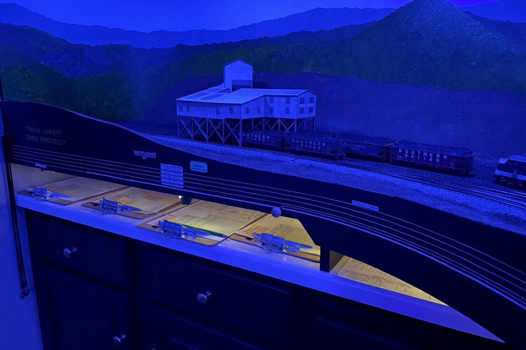
Cheap strings of LED Christmas lights light up the aisles and staging yardsLED Christmas lights illuminating the paperwork area under Mayflower
All told, the layout will need about 45 of these bulbs. At ~$6.50 apiece, it’s not the cheapest option, but I’ve been very happy with the results! Hopefully I’ll get at least a few years out of the bulbs before having to replace them. I’ll keep playing around with the colors and intensities and seek feedback from other operators and will share what I learn over time.
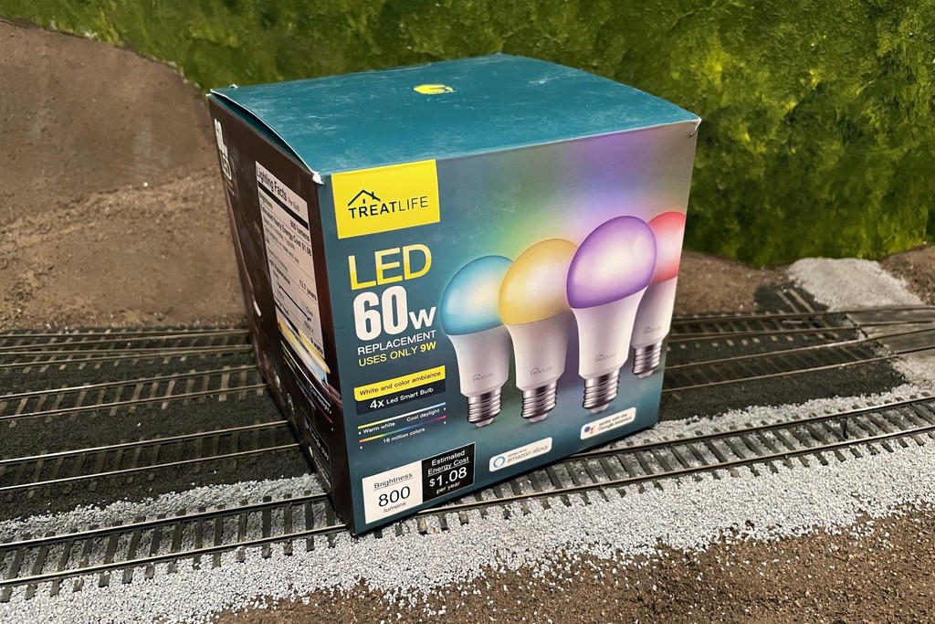
Here’s what I’m using, TreatLife 60W equivalent (9W actual) multi-color LED smart lights
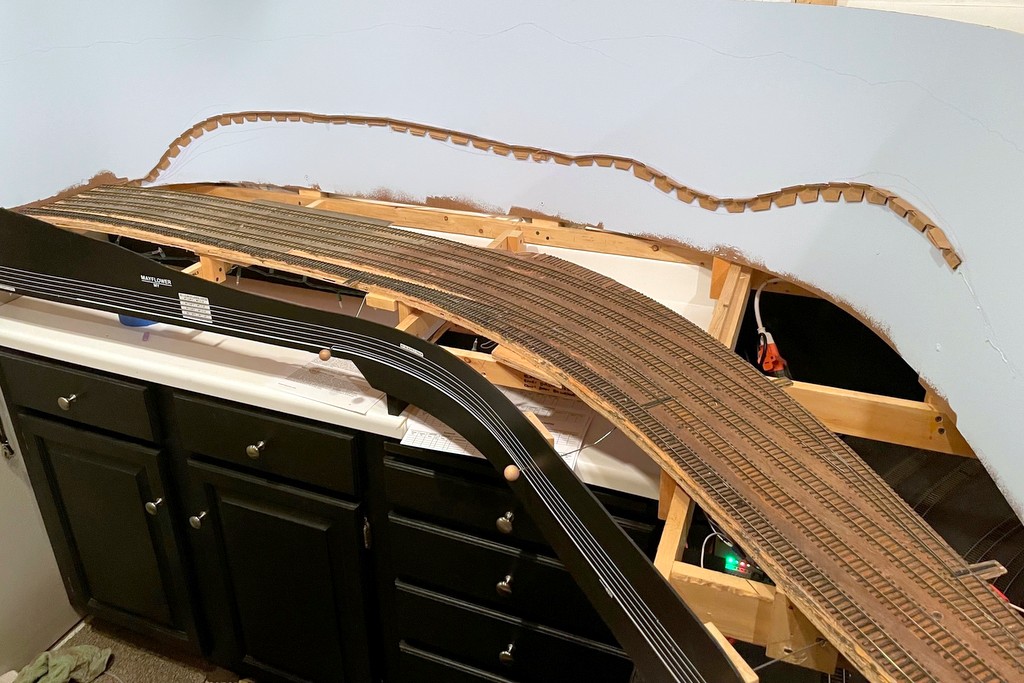
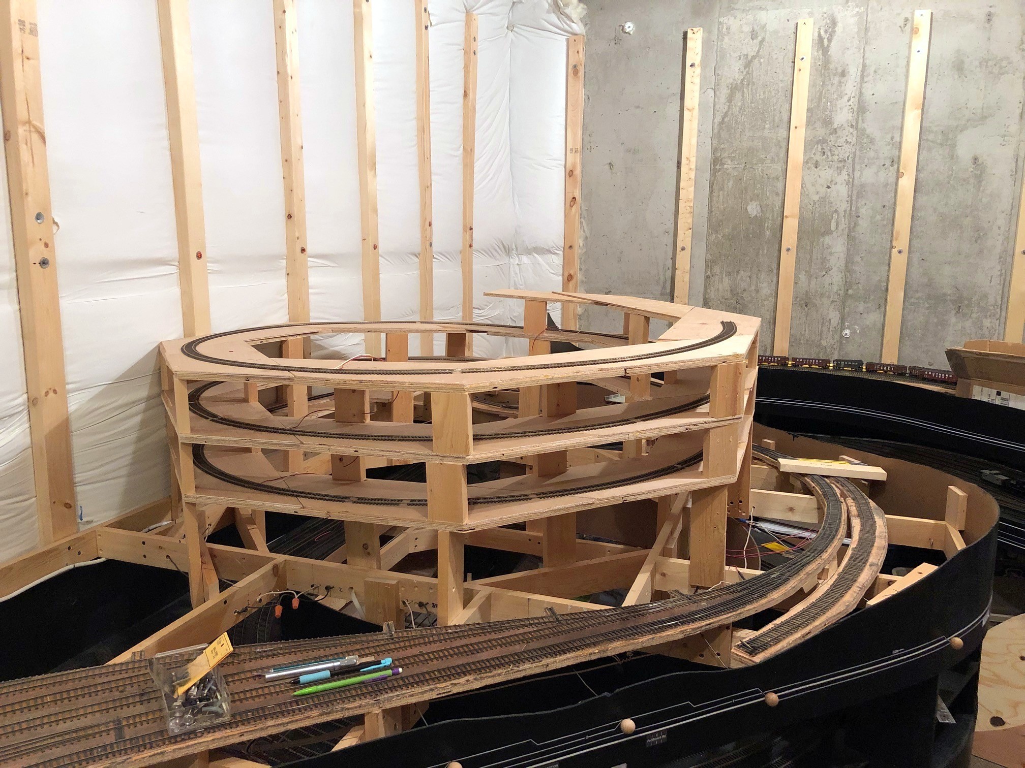
A shot from the door of the completed upper-deck benchwork
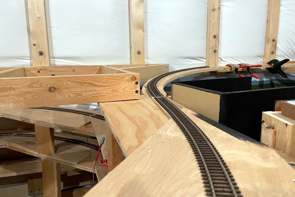
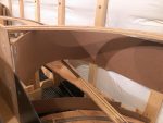
The layout passed another milestone this past weekend–the upper-deck benchwork is now complete! Most of it was pretty straightforward, and the average deck height (top of benchwork) is 60″. A few sections required some creative engineering and some non-90 and 45 degree cuts. One tricky section was the top of the helix where the tracks transition through the upper deck benchwork. I used a piece of elevated benchwork and a plywood bridge to make this transition.
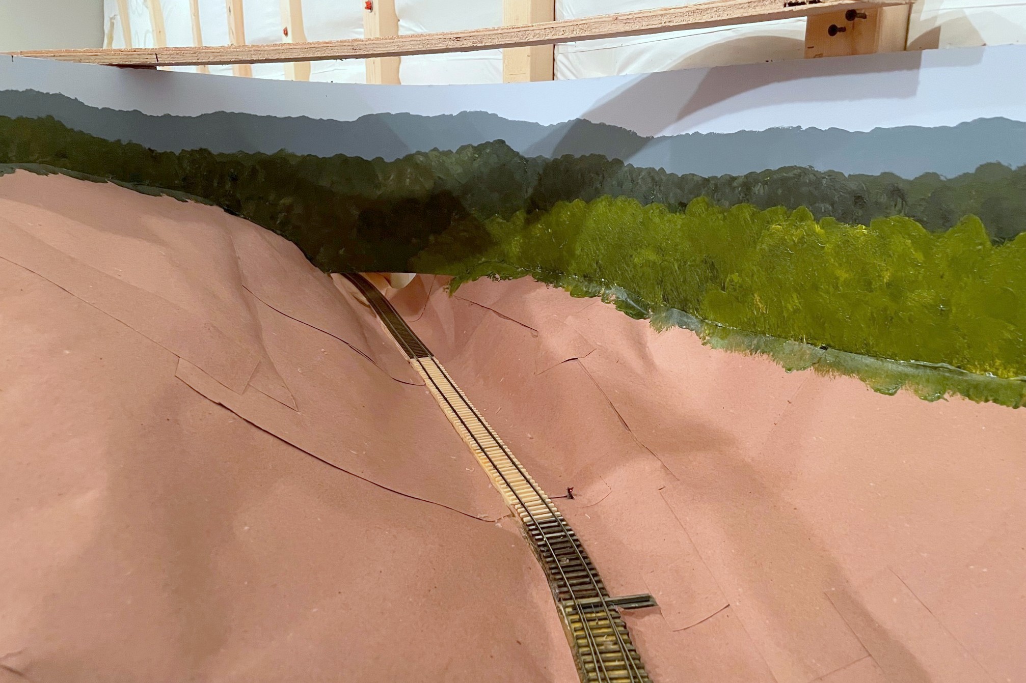
This was a challenging section to engineer–the track comes off the helix, ducks under a piece of elevated benchwork, then runs on top of the upper deck
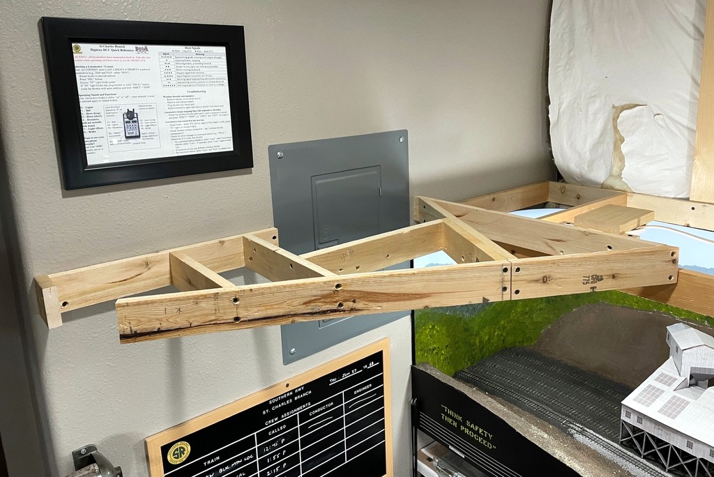
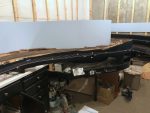
Another tricky section was the last piece which holds the tail track for the switchback to Benedict at the end of the line. This piece goes in front of the basement breaker panel, so I had to engineer it so the door can be easily and fully opened and accessed, and I designed this section to be removable in case any major work is required someday. As you can see from the first photo, the lighting is in but very visible–these will be hidden behind fascia once the upper-deck trackwork is in.
This was the last piece of benchwork for the upper level. This piece allows the breaker box to be opened, and it’s removable in case there are bigger issues
Here’s a representative CV Local with an RS3, 11 hoppers, and a cab nearing the top of the grade
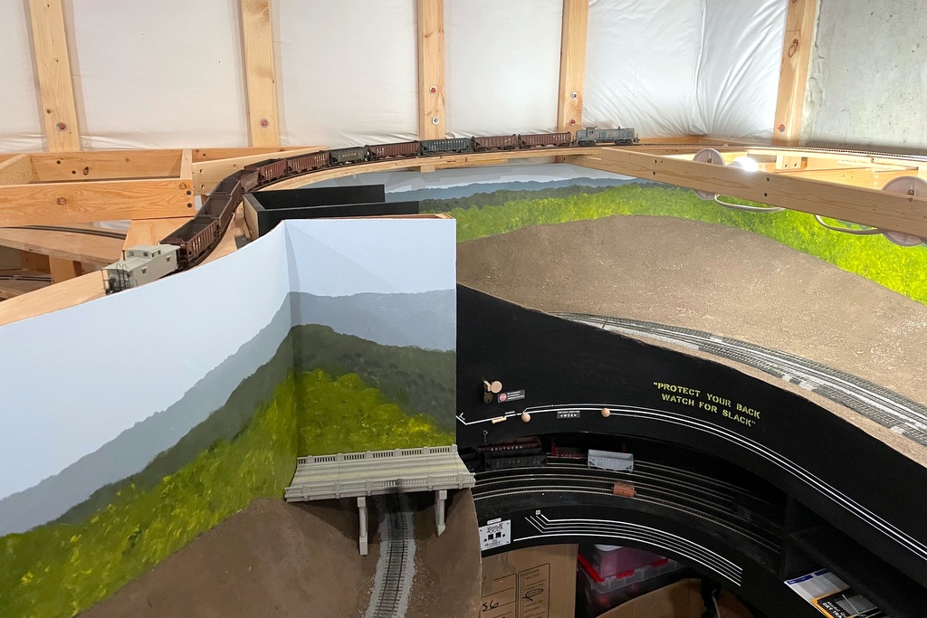
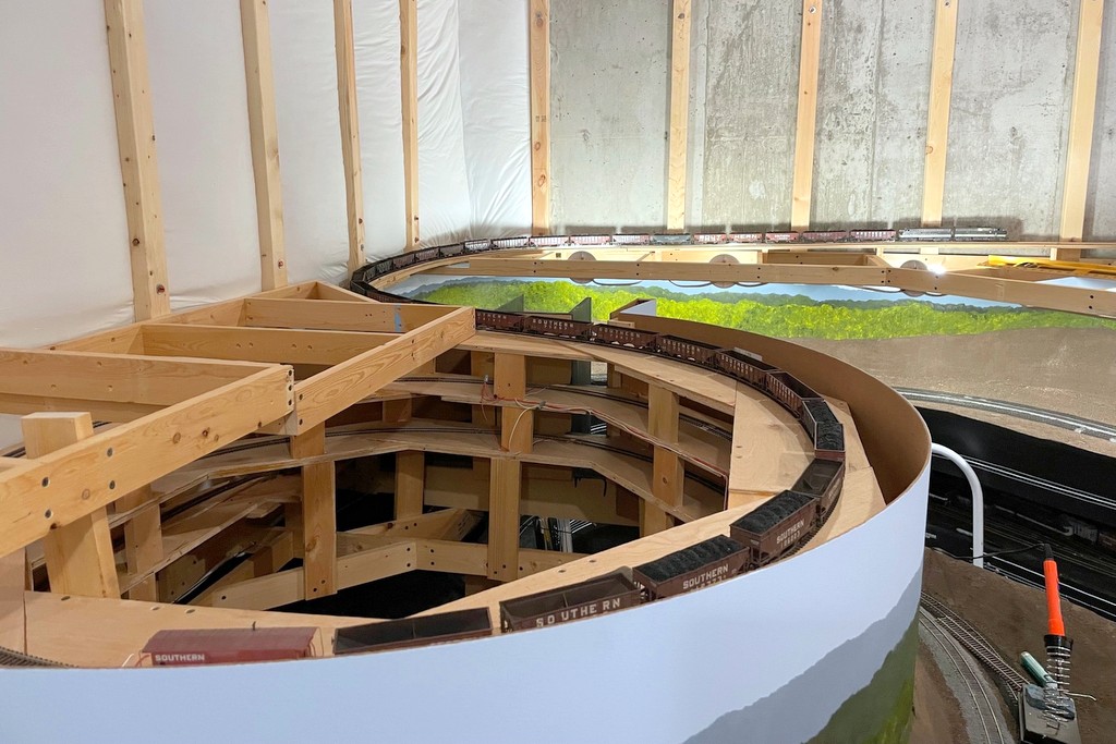
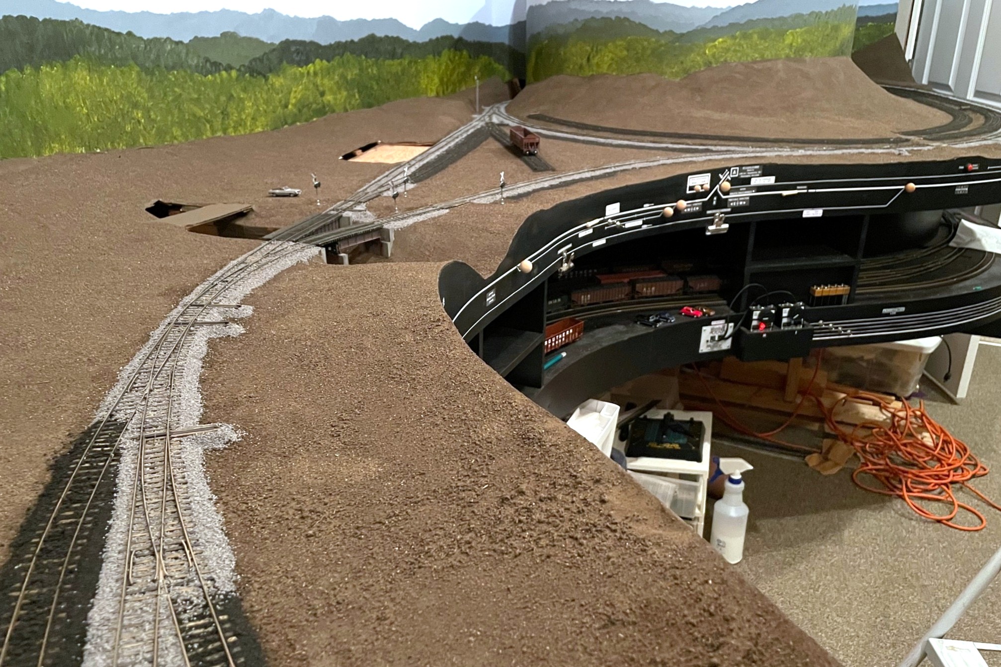
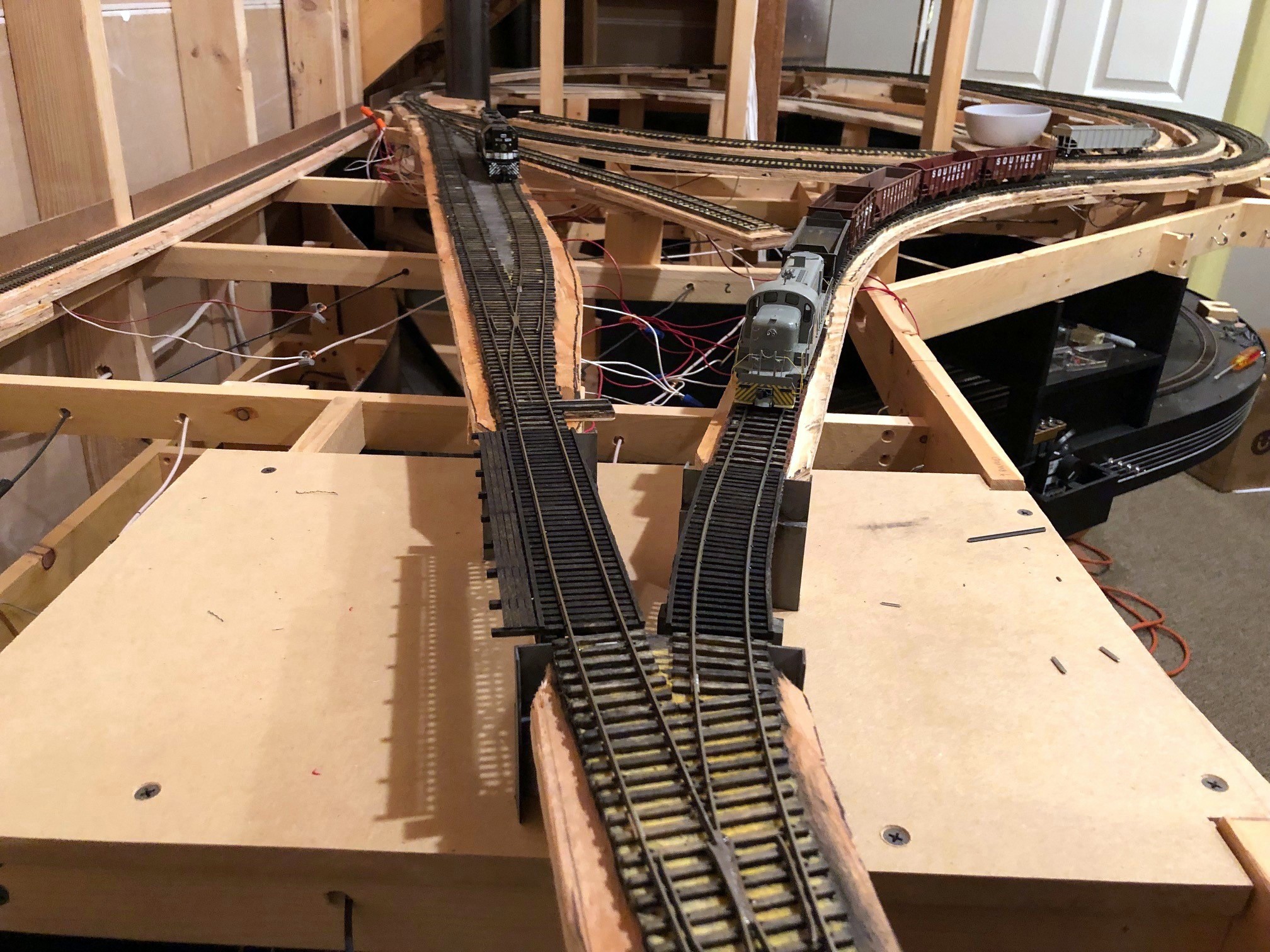
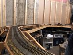
With a portion of the upper-deck benchwork in place, I was able to complete the connector track from the top of the helix to the top of the grade along the back of the layout. The moment of truth had arrived where I would figure out if a key assumption I had made would hold true. My helix is aggressive: 24″ radius and 3% grade! At the top of the helix is an S-curve into another 24″ curve in the opposite direction and a short straight section to reach the top of the grade. Based on experience with the first helix (also 24″ radius and 3% grade), I estimated my lightest engine could pull about a dozen empty hopper cars and a caboose up the helix. The lightest engine is an Athearn RS3 used on the CV Local, and in the 1960s and early ’70s, this job only hauled a handful of cars onto the St. Charles Branch, perhaps 6-10 on a given day.
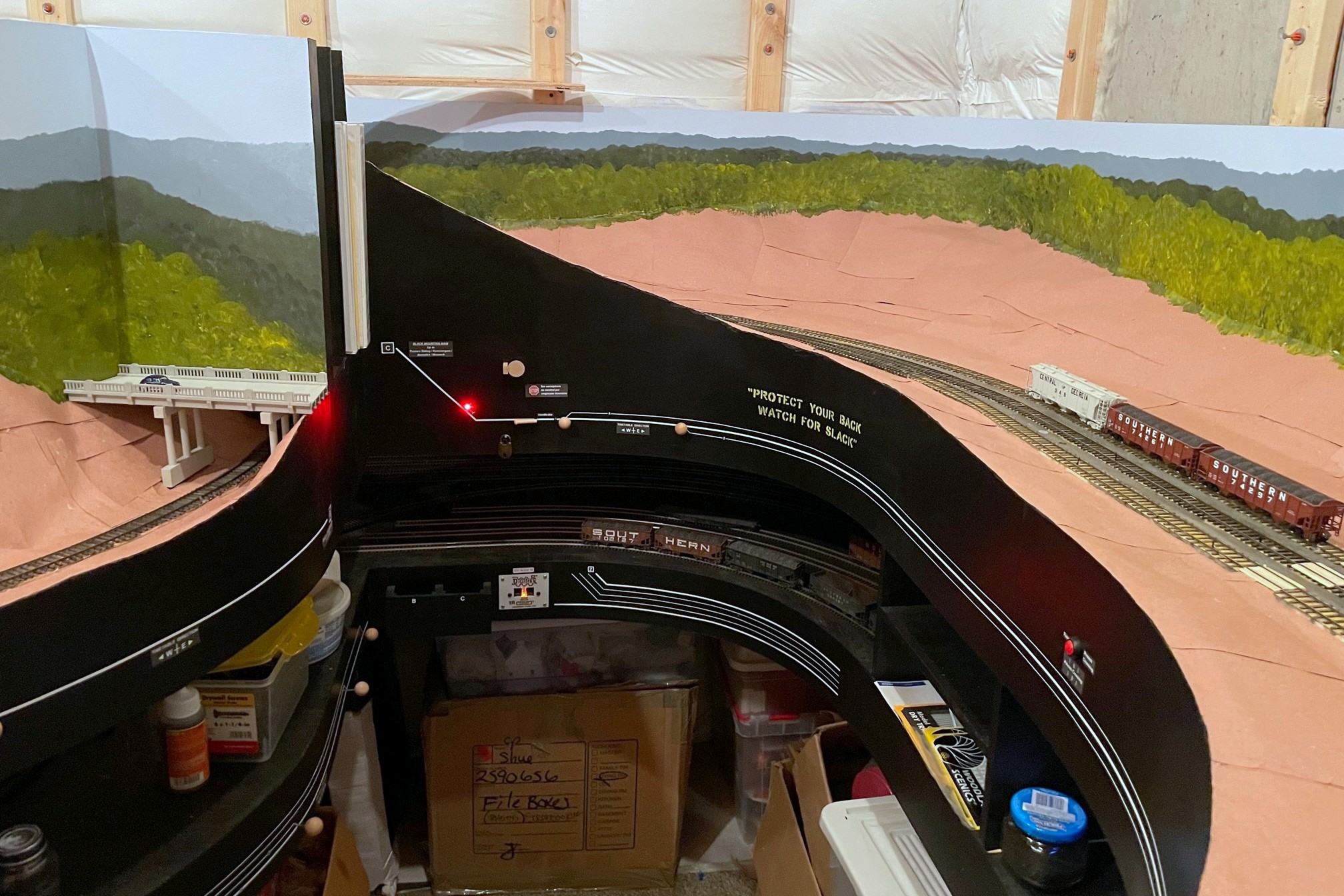
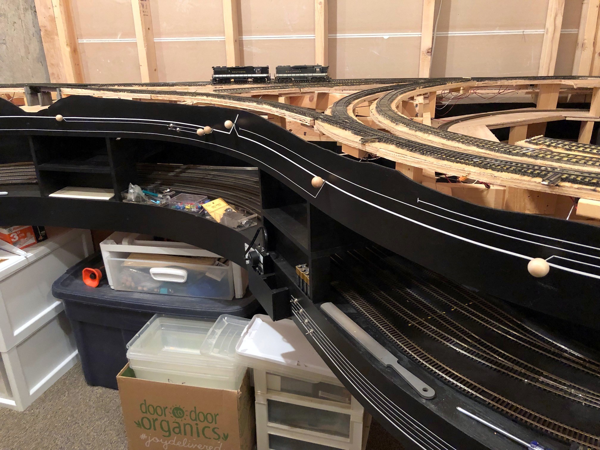
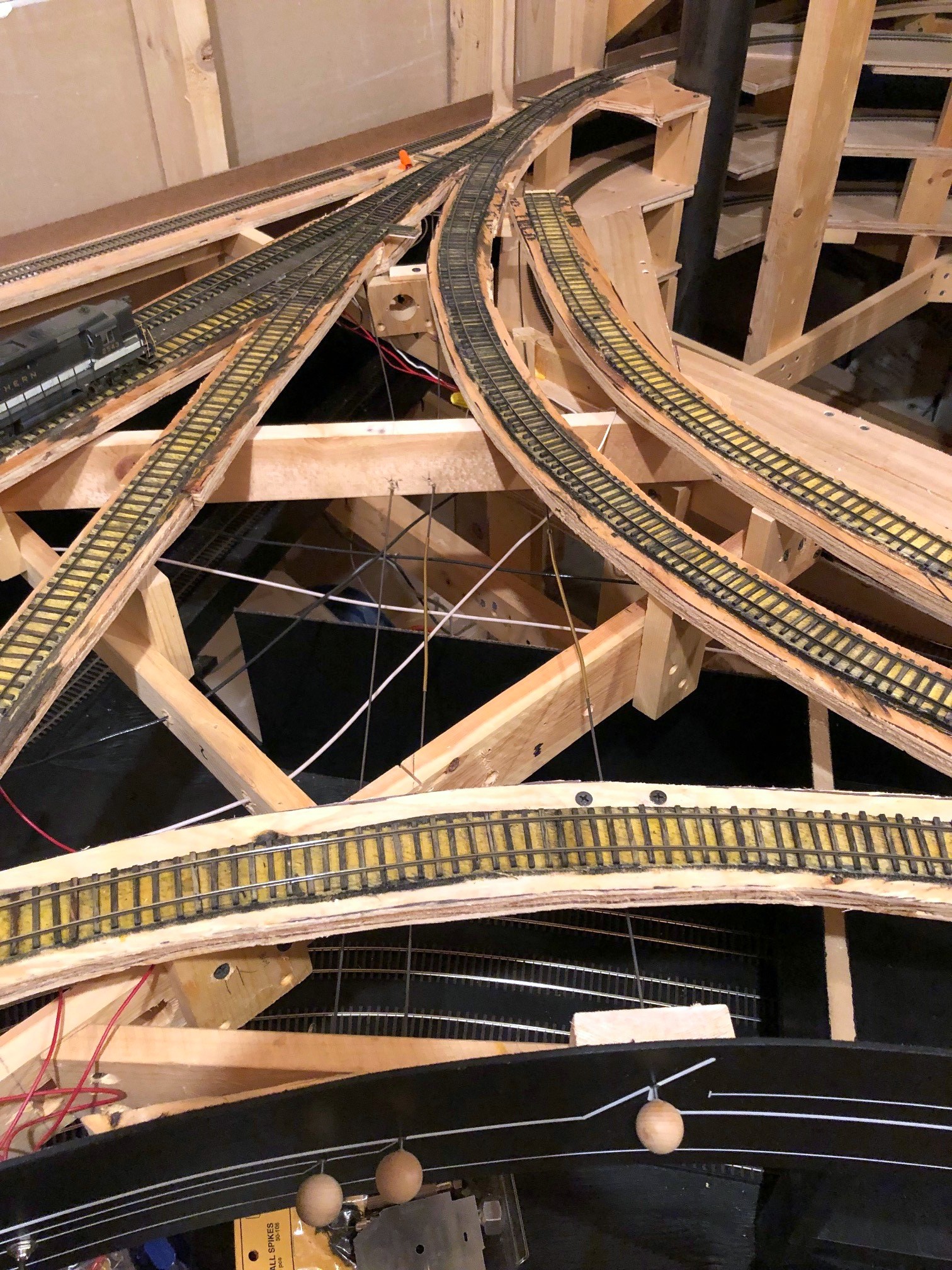
Here’s the track where it exits the helix and continues up-grade to the right through the upper-deck benchwork
I loaded up an RS3 with 12 cars (including 3 really heavy Tangent cars) and headed for the first helix. With the Tangent cars, the RS3 stalled out on the grade–uh oh! I removed one hopper and tried again. Thankfully it was able to climb the first hill, albeit with the throttle at 1/4 speed and the Tsunami2 howling at run 8! After a brief respite of relatively level track in St. Charles, the train attacked the second helix to the upper deck. Three-and-a-half turns and 20″ higher, the train exited the helix and entered the S-curve, coming to the crest of the grade without stalling. So, 11 cars is my current limit, and while it’s slightly less margin than I had hoped, it’s good enough that it won’t restrict my operating scheme.
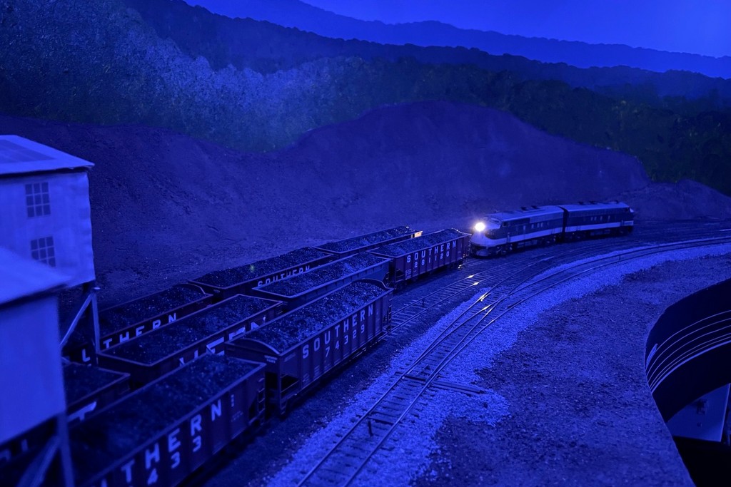
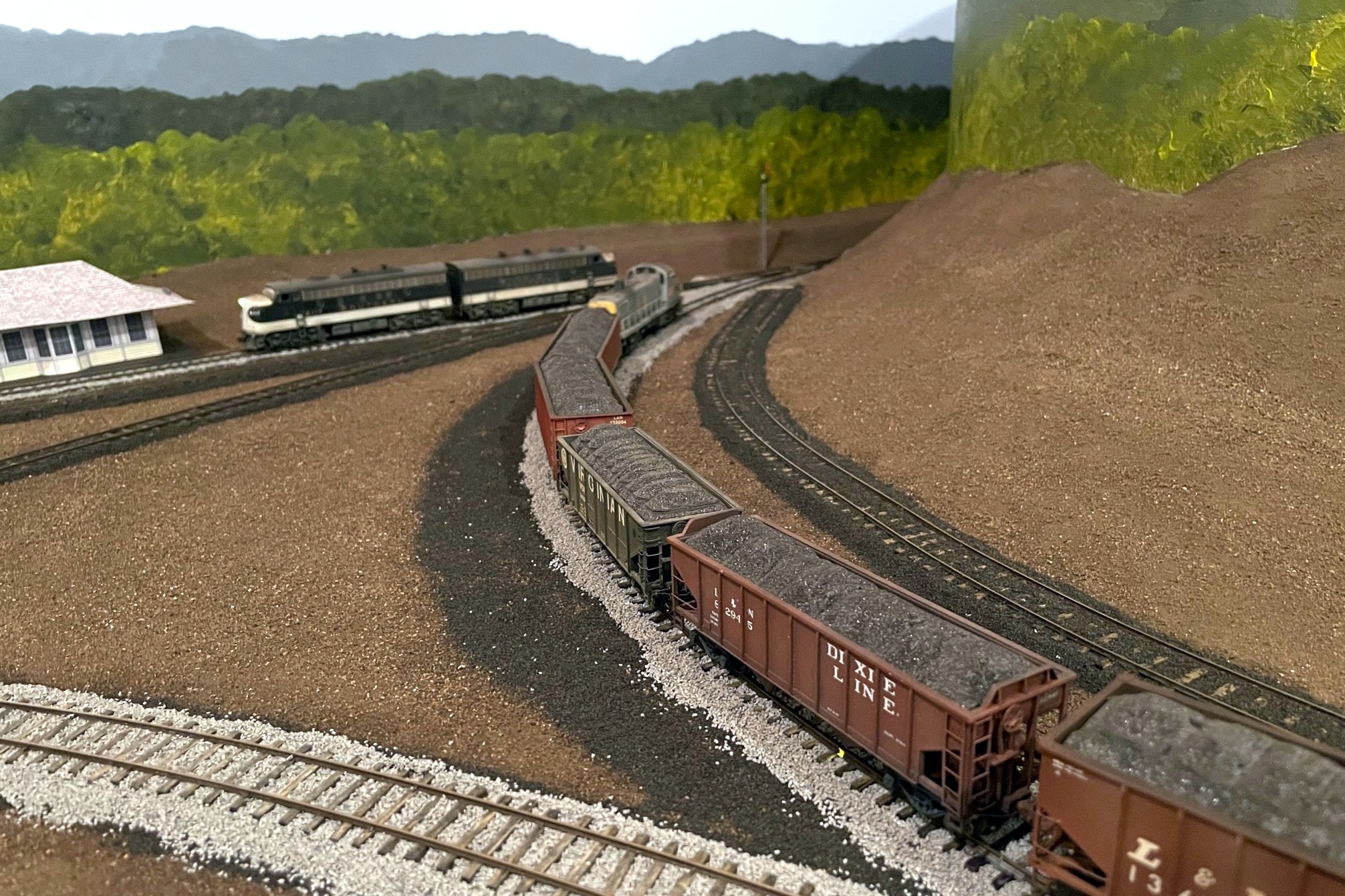
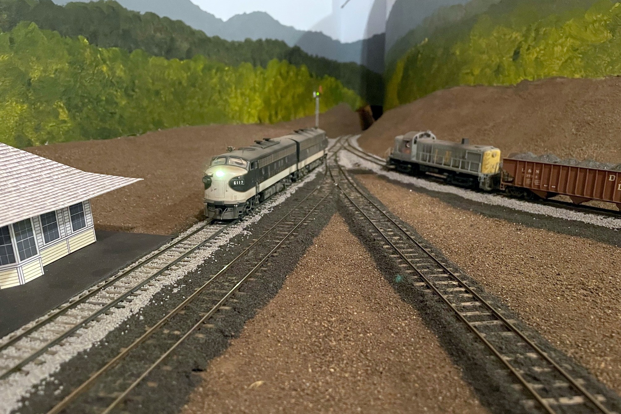
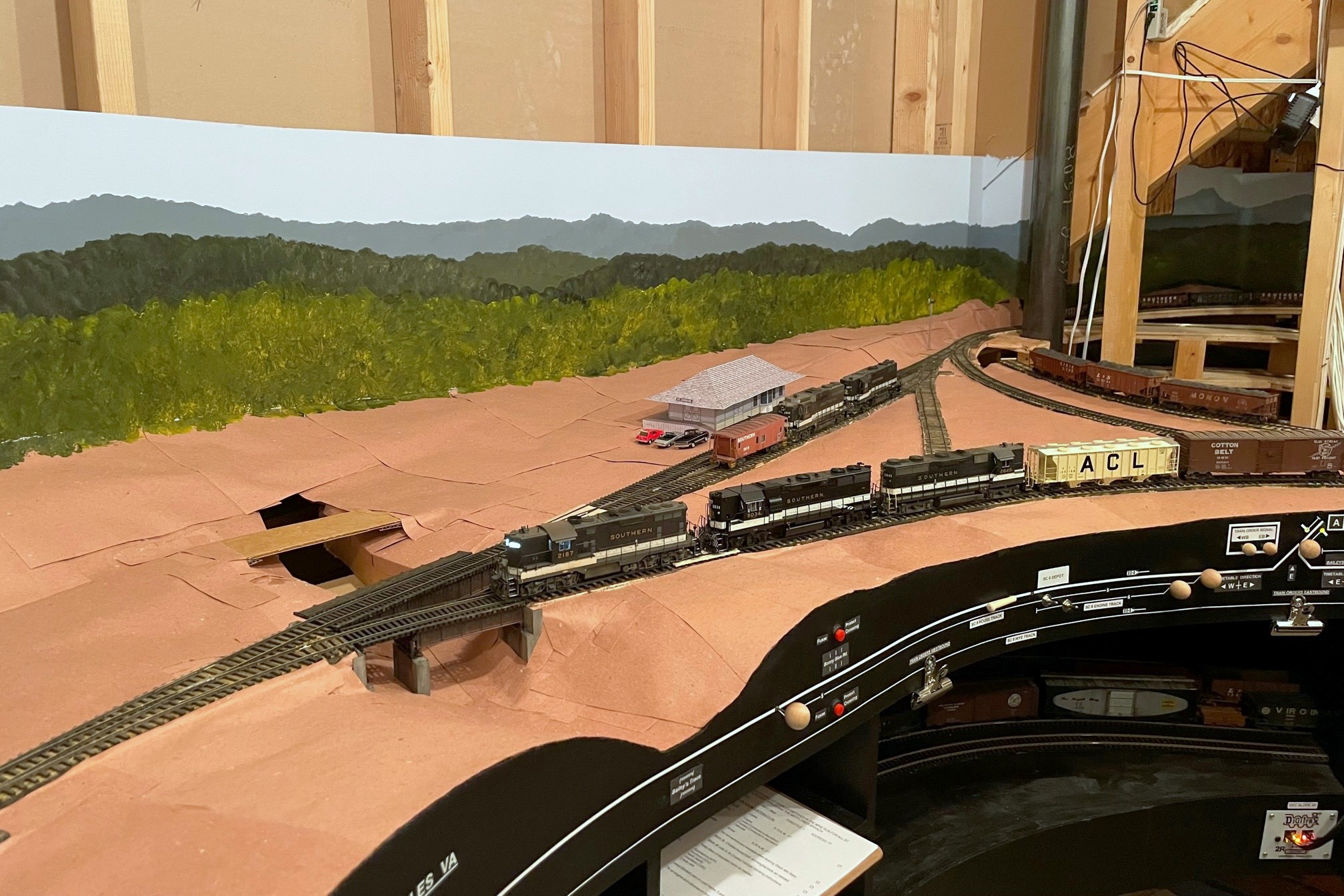
Two Southern F-units have no trouble pulling 33 cars to the top of the 3% grade
Just to be sure, I latched a pair of Intermountain F7s to 33 Southern hoppers and tried the same thing. No problem! Two locomotives have plenty of power to haul more than enough cars up the grade. It was cool to see trains actually running on the upper deck, even if the section they’re currently in will be hidden by hills.
The first layout lights are in! Here’s the “cool white” that I like for daytime
While my light is nowhere near as impressive as God’s light in Genesis, it still makes me glad to see a little more light on the trains in the basement. Now that I’ve got some upper-deck benchwork in, it opened the way to try out the layout lighting I’ve been wanting to do for a while. I’ve looked into LED strings and other bundled lights, but in the end, I’ve settled on using individual multi-color LED “smart lights” I can control with my phone. It’s not the cheapest solution (about $7 a bulb, and my layout needs 40), but it’s bright, and they’re customizable for a dizzying array of colors and brightness!
This is a more modern evolution of the lighting on my last layout which used cheap plastic fixtures and compact 40W lightbulbs. I was able to recycle the fixtures and wiring for this project, but the technology is so much better than my previous little analog dimmer. Not only are the LEDs brighter, but they run cooler, only use 9W each, and I can get a nice “cool white” that looks a lot more like sunlight than incandescent lights. I was also able to play around with the colors and dimmer, and a wide range of effects are possible including a nice moonlit night and a warm sunrise/sunset. It’s also easy to “group” them so one command changes all the bulbs simultaneously.
The dimmable, multi-color LEDs can give a lot of different moods like this “moonlit night”
I’ll keep playing with them to try to mitigate the glare spots and shadows. I’m also going to figure out a way to automate going from nighttime to sunrise to day–I’m sure it’s possible with all the Smart Home controls out there now. One thing I hadn’t counted on is the lit portion of the bulb is about 2″ further out from the fixture than the old incandescents. For now that’s creating more shadow along the front of the layout than I’d like. When I put the valance in for the upper deck, I’m inclined to move it out over the aisle a few inches to try to improve this, and I might mount a few of these in the overhead fixtures as well. For now, I’m calling this experiment with 8 bulbs a success, so now I’ve ordered more to keep working around the rest of the layout.
The fixtures for the lighting are simple plastic screw-in basesHere’s what I’m using, TreatLife 60W equivalent (9W actual) multi-color LED smart lights
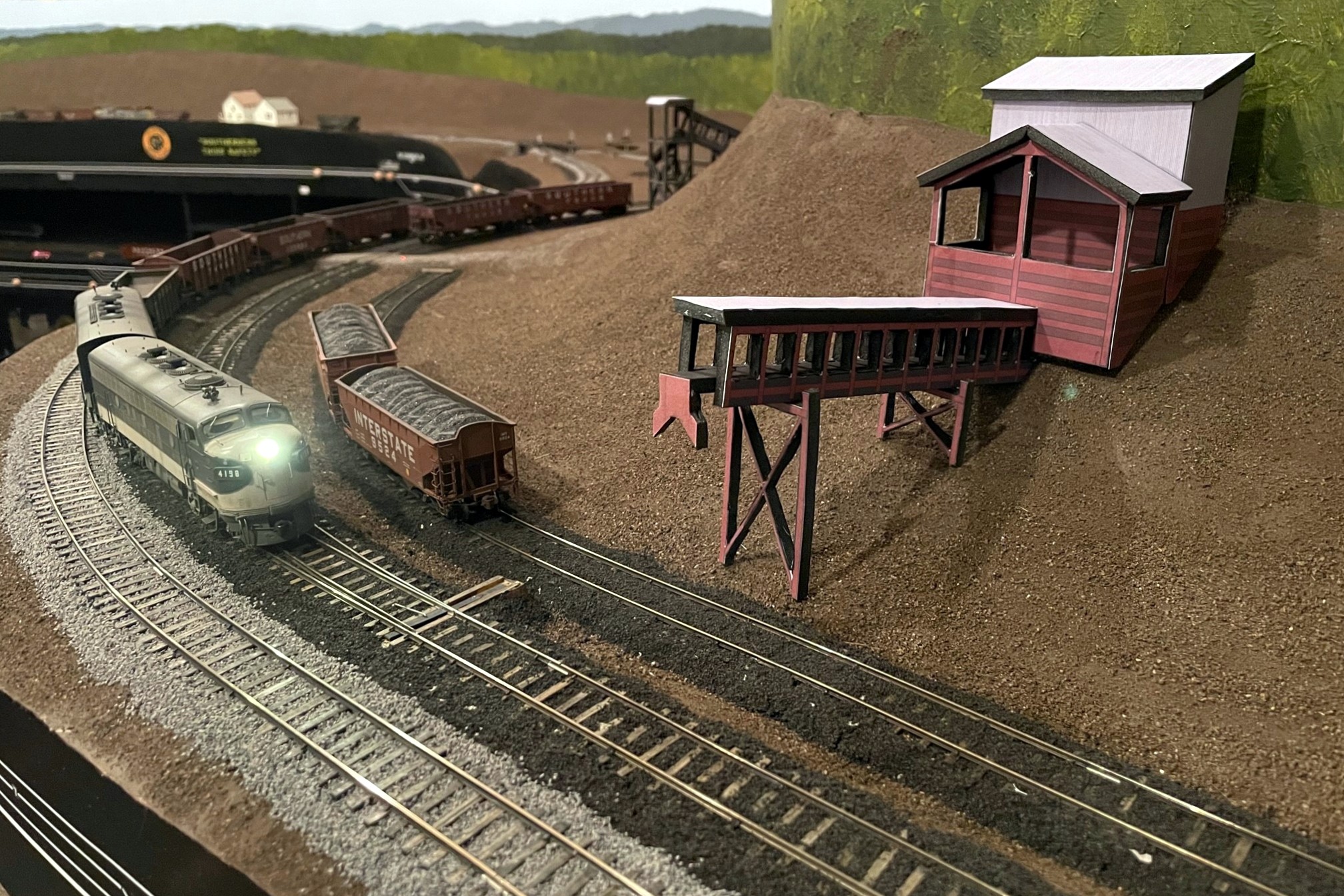
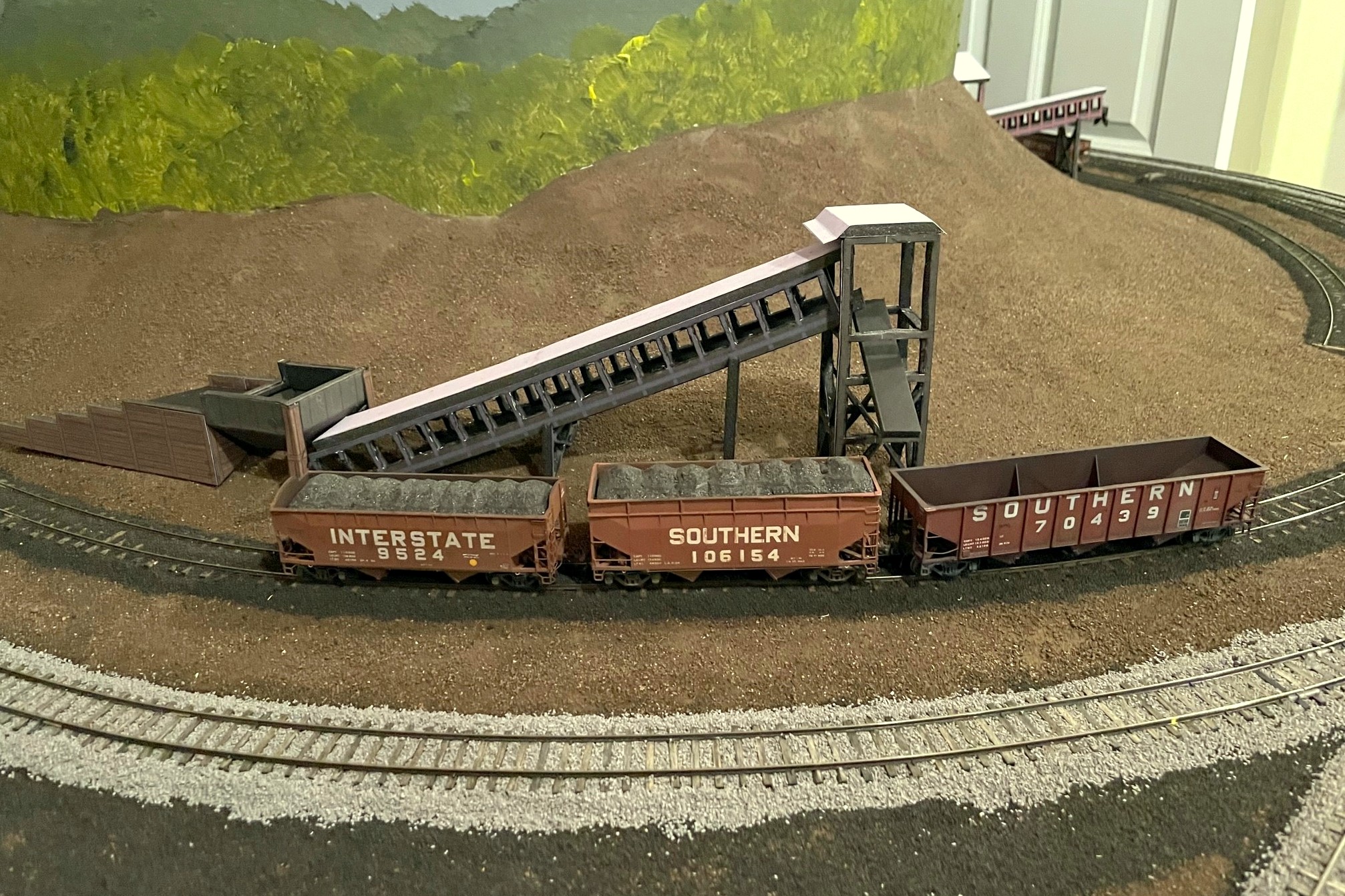
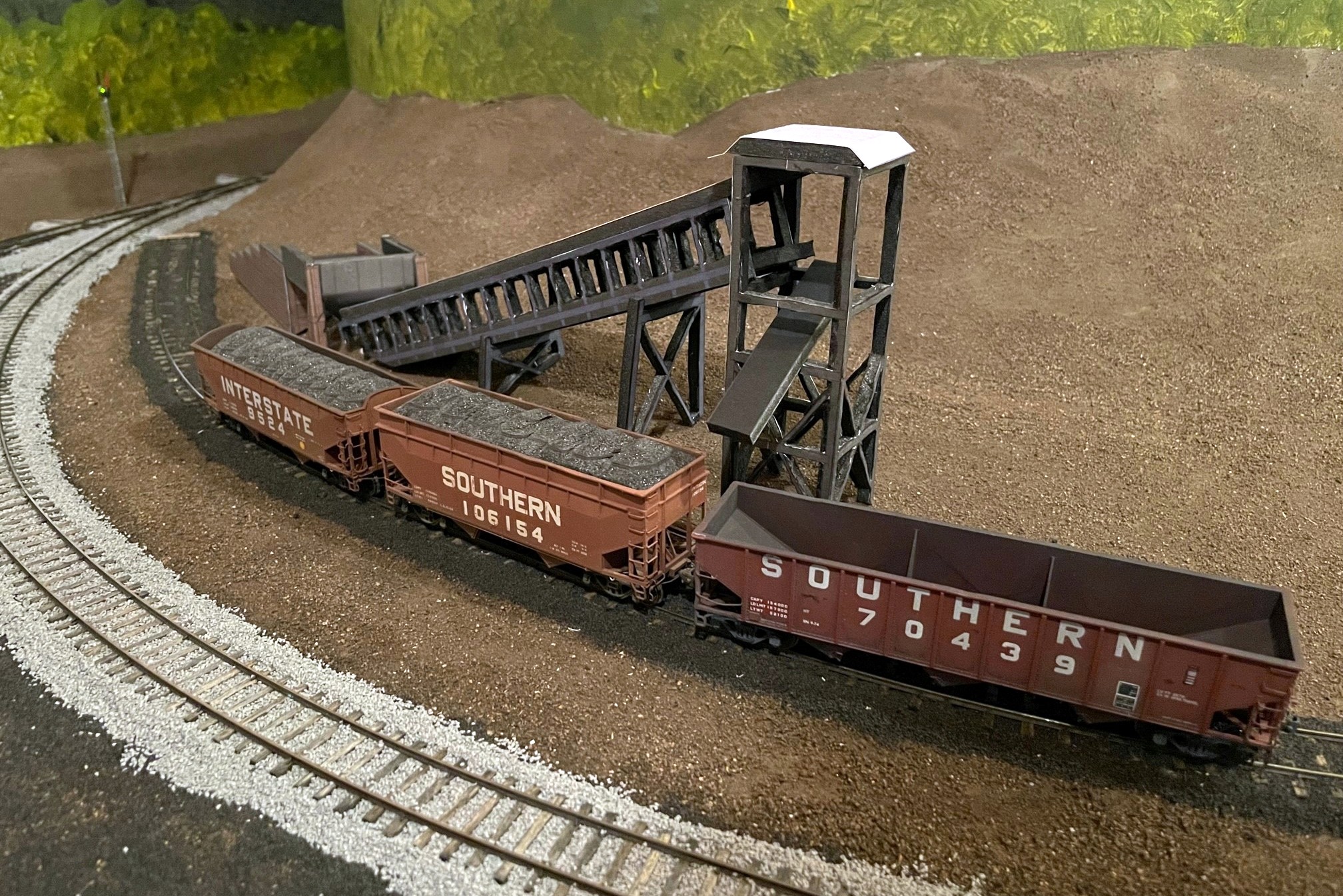
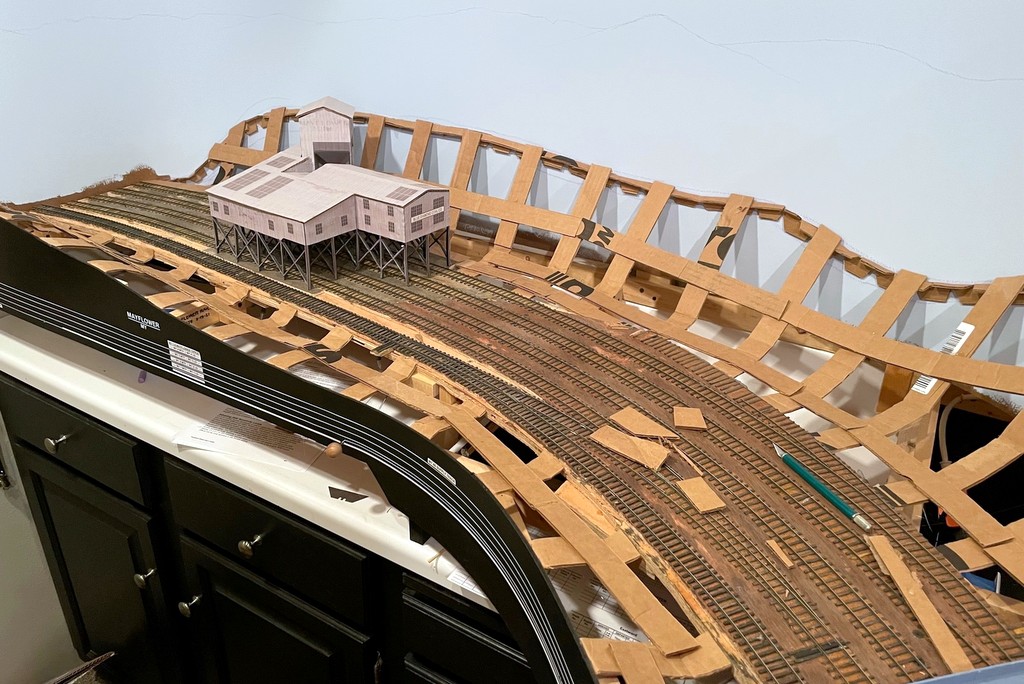
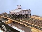
Here’s the full mocked-up scene with the St Charles Switcher preparing to swap empties for loads at the JAD Turner loader–the St Charles loader can be seen just around the hillside
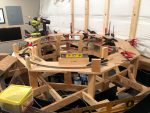
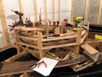
As I’ve discussed previously, I like to build mock-ups out of foam core and paper of the larger structures on the layout that I will eventually scratchbuild. This serves three purposes. First, it gives me an opportunity to create a line-drawing / blueprint and make sure the drawing works before cutting more expensive materials. Second, it allows me to visualize a scene and make adjustments before I build the permanent structure. And third, it gives me a good stand-in on the layout until I can build the real one–something that makes operations a lot more fun than imagining there’s a big structure where you’re switching! For this third reason, I put a little extra effort into the drawings to give them some color and texture. I’ve covered the techniques before, so I won’t repeat them here.
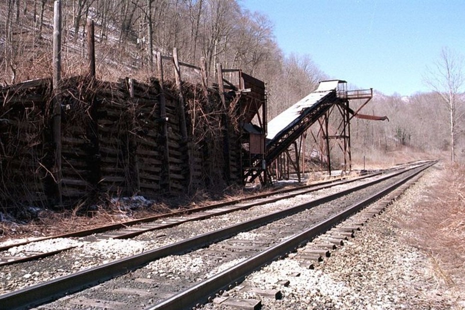
This project involved the two “truck dump” tipples that were built in the late ’70s (as far as I can tell) near St Charles, VA. One is known as JAD Turner, and it’s probably still standing today. The other sat on the wye at St Charles for just a few years–I don’t know it’s name, so I’m just calling it the St Charles loader (super original, I know…). What made this project challenging is I didn’t have any good photos of the loader configuration I needed to model. JAD Turner was modified over the years with a second conveyor and second empty track, but the earliest photo I have of it (a grainy aerial from 1981) clearly shows only a single conveyor. I’m modeling it as if it’s the same tipple but with fewer added parts, so I took the dump shed / crusher section of the current loader along with a single conveyor and came up with this design that looks reasonably close to the aerial.
Here’s the JAD Turner loader near St Charles in the late ’90s with additional chutes added, but I modeled the core dump shed, crusher, and one of the conveyors (Robby Vaughn photo)Here’s the finished JAD Turner loader mock-up complete with a little double chute over the rails
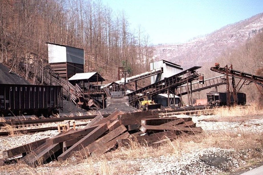
St Charles was a little more challenging as the ONLY photo I have is a grainy aerial from 1981 showing what looks like a pile of coal, a conveyor (maybe two), and what looks like a dump ramp but no shed. I didn’t have to look far to find something close. Just up the road between St Charles and Mayflower was a loader known as “Southwest” which had a similar dump and conveyor arrangement. Southwest was built after my era, so I won’t have to have two similar looking loaders on the layout. Who knows, perhaps they moved the loader from St Charles up to Southwest? That’s my story until someone proves otherwise…
The Southwest loader sat between St Charles and Mayflower but after my era–I’m using it as the prototype for my St Charles loader (Robby Vaughn photo)A view of the St Charles loader mock-up showing the ramp and dump area
Anyway, here are the results, and I’m really liking the scene now. I can’t wait to build the real things! But first the upper deck…
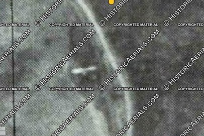
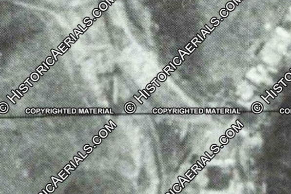
This grainy aerial photo from 1981 (courtesy of the awesome HistoricAerials.com website) clearly shows a single conveyor at the JAD Turner loadout, so I removed “extra” parts from the ’90s loadout to get my design
Here’s the JAD Turner loader near St Charles in the late ’90s with additional chutes added, but I modeled the core dump shed, crusher, and one of the conveyors (Robby Vaughn photo)
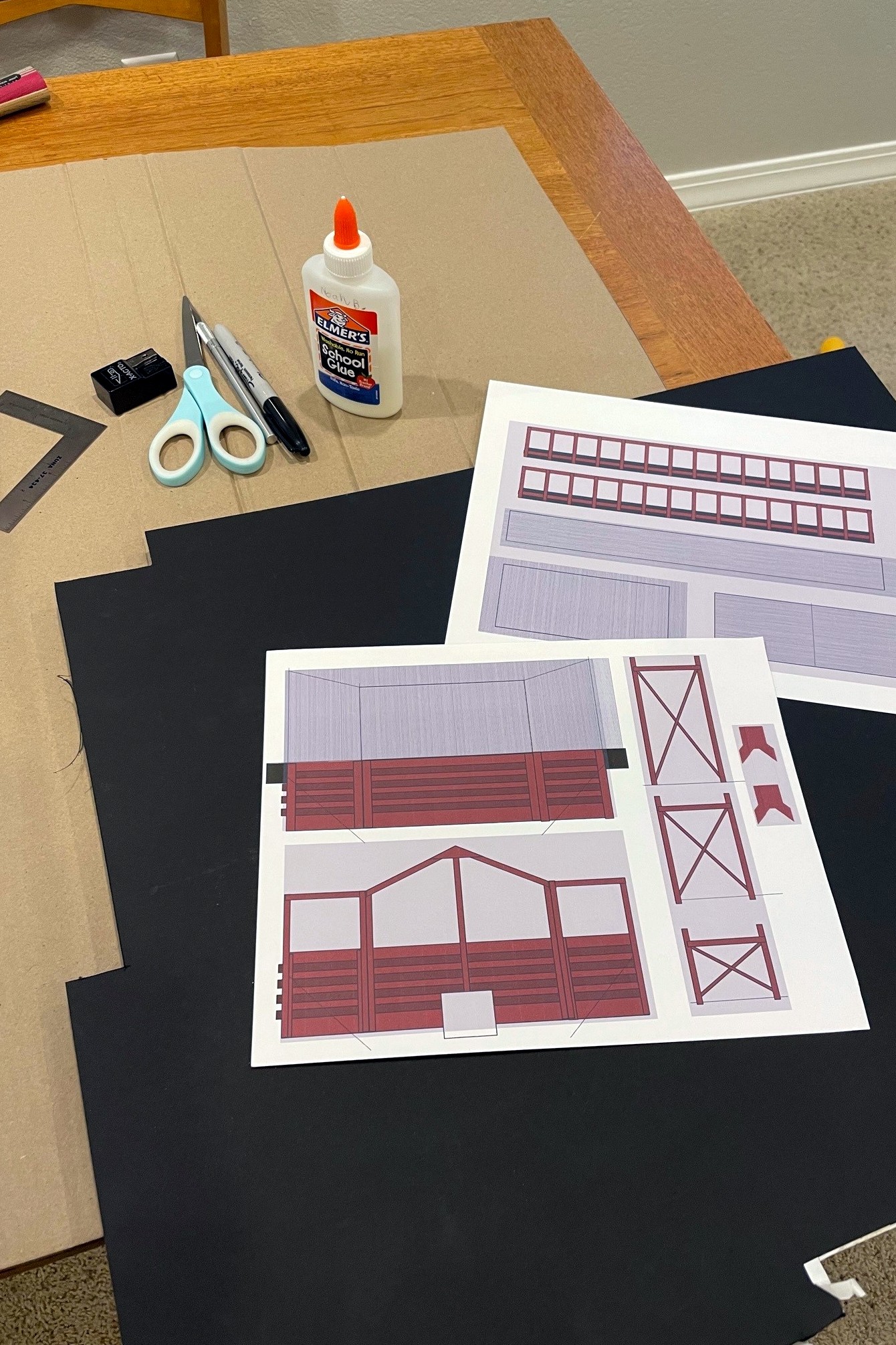
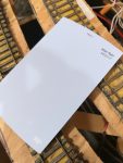
Here’s the drawings I did for a JAD Turner loader mock-up using MS PowerPoint along with the supplies needed to build the “paper doll” mock-up
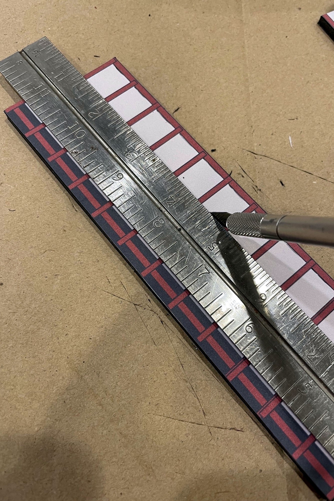
I used a sharp X-Acto blade to cut out the structure details for the conveyors and legs
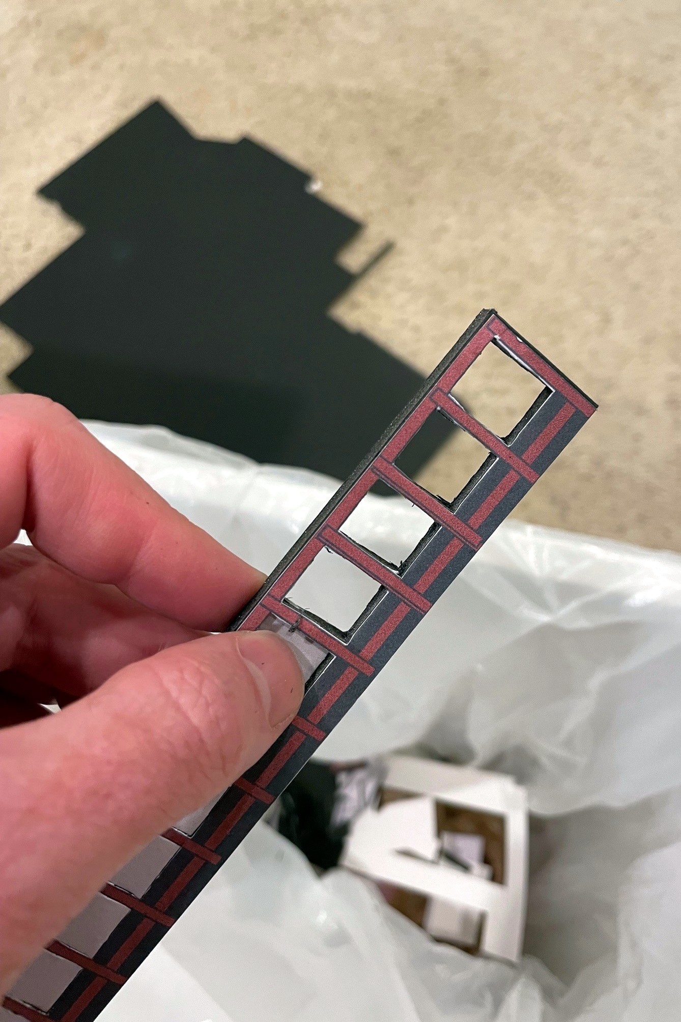
Once the area has been well scored front and back, it’s pretty easy to just pop it out of the foam core frame
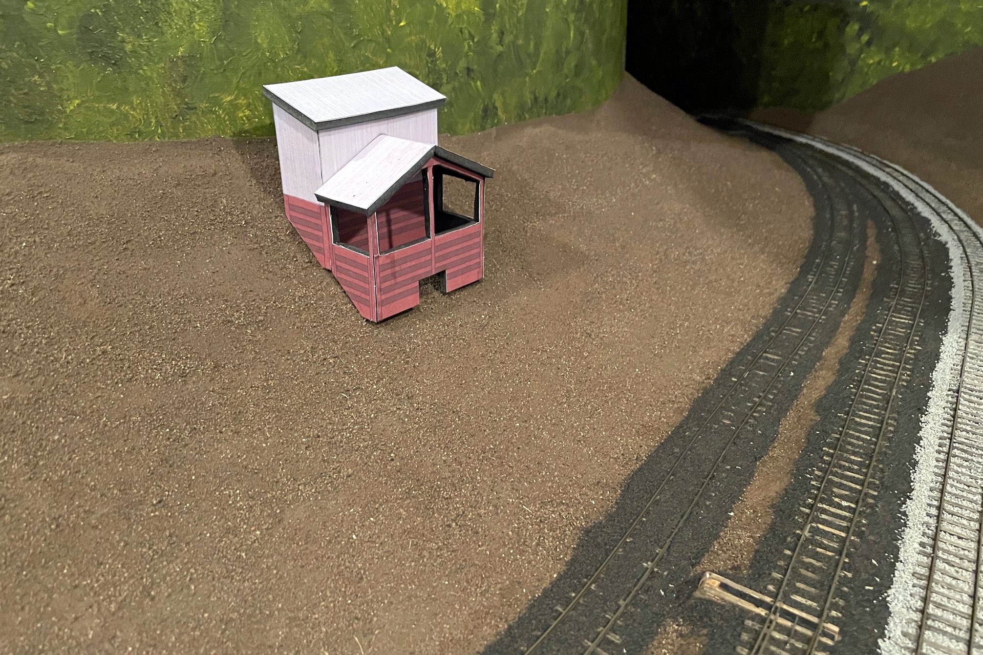
Here’s my dump shed and crusher bin mock-up for JAD Turner. I used an X-Acto to fit it to the hillside
Here’s the finished JAD Turner loader mock-up complete with a little double chute over the rails
This grainy aerial view of the St Charles loader circa 1981 (courtesy of HistoricAerials.com… awesome website) is all I have from which to base my loader model
The Southwest loader sat between St Charles and Mayflower but after my era–I’m using it as the prototype for my St Charles loader (Robby Vaughn photo)
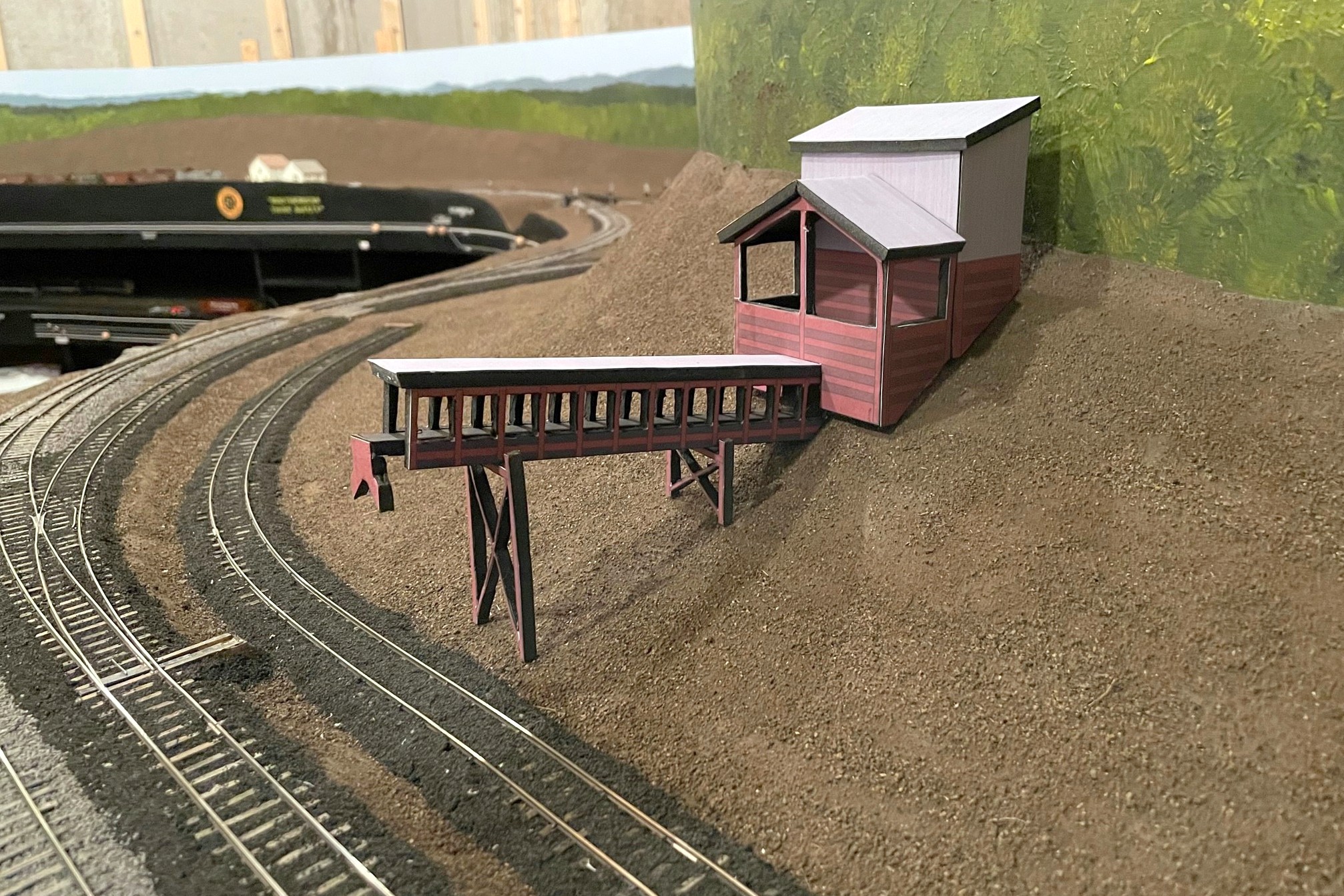
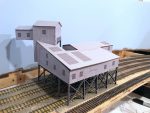
Here’s the finished mock-up for the St Charles loader in place along the wye
Another view of the St Charles loader mock-up showing the ramp and dump area
Here’s the full mocked-up scene with the St Charles Switcher preparing to swap empties for loads at the JAD Turner loader–the St Charles loader can be seen just around the hillside
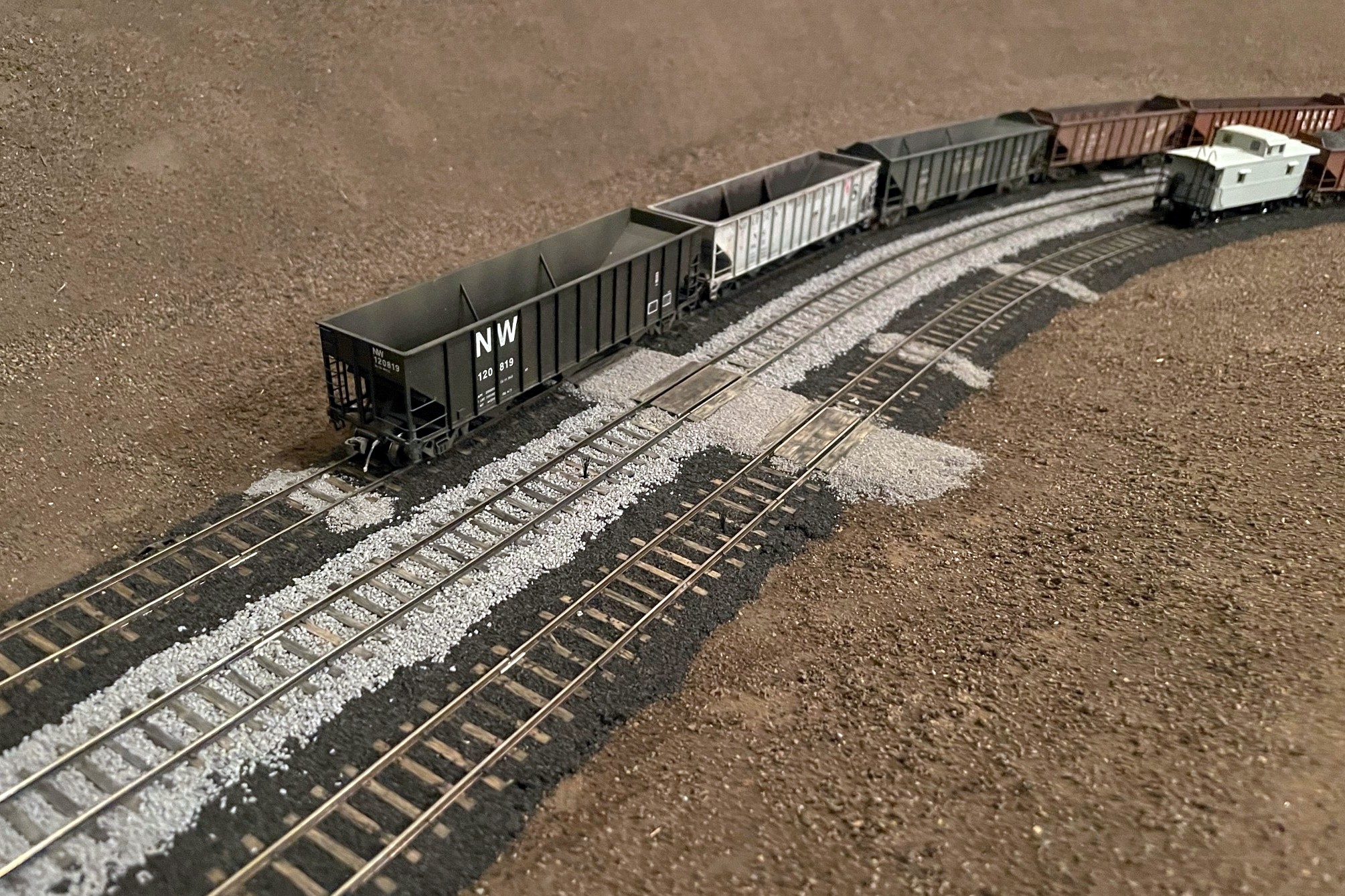
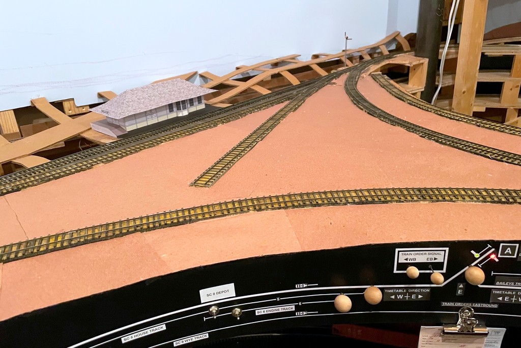
Here’s the St Charles wye with ballast. Note the area of cinders where a track used to be
While I finished the basic scenery forms on the lower deck a few weeks ago, I decided it would be better to ballast the tracks before adding the upper deck benchwork while I still had good access to them. I’m so glad I did because ballasting gives the scenes a much more “finished” look even though there’s still a ton of scenery work to be done. I’ll be honest, I was dreading ballasting the track–I had little experience with ballast, but from that experience I saw it as a frustrating, tedious, and time-consuming job. I have now changed my tune! While it’s still time-consuming, I was able to learn and mature my techniques quickly to avoid the frustration and tedium, so I’ll pass along my method here.
First, I had to determine what kind of ballast I needed. This wasn’t as straightforward as I’d hoped. As best I can tell, most of the tracks in my area were at one time ballasted in cinders harvested from steam locomotives. The steam locos went away in the 1950s, and with them the ability to get cheap and ready cinders for ballast. Photos from the ’80s and ’90s clearly indicate most everything got covered in rock ballast–would the cinders still be around in the 1960s and ’70s? After some digging online, I found that cinders in many places lasted for decades after steam, and in the coal fields, it’s tough to tell cinders from spilled coal anyway, so an added incentive for cinders, at least on sidings and secondary tracks. For the main tracks, photos show the Southern’s ballast in this area was a medium gray. I toyed around with trying to find some actual rock to use as ballast, but in the end I decided on good old Woodland Scenics products made from crushed walnut shells because I can find it readily, it doesn’t cost an arm and leg to ship, and it’s pretty easy to work with. I used fine cinders and medium sized gray ballast in the big shaker containers for this project, and I was able to do the entire lower deck (12′ x 16′) with just under two shakers of each color (4 shakers total).
Second, I did a bunch of research on how to apply ballast, and I am so glad I did! In the end, I went mostly with the method Cody Grivno of Model Railroader lays out in the article here. The only other materials I needed were white glue (I bought a gallon), isopropyl alcohol (I used about XX oz), and dish soap. For tools, I used a spoon, a large flat brush, a white glue dispenser (like the ones kids use in school), two small jars with eyedroppers, a work glove, and my fingers. In the glue bottle, I mixed up some “just a bit wet glue” which is about 2 parts white glue, 1 part water, and a drop or two of dish soap–when you squirt it out, it should dissipate from its bead but not run. In one of the jars with an eyedropper, I made a mix of “very wet glue” of about 1 part glue, 6 parts water, and a drop or two of dish soap–it should look about the consistency of milk and absorb into the wet ballast (I’ll explain that in a minute) after a few seconds. You’ll need a LOT of the very wet glue, so you can either make a big batch or mix it on-demand when you run out (what I did… it was a lot of trips). The remaining jar and eyedropper are for the isopropyl alcohol.
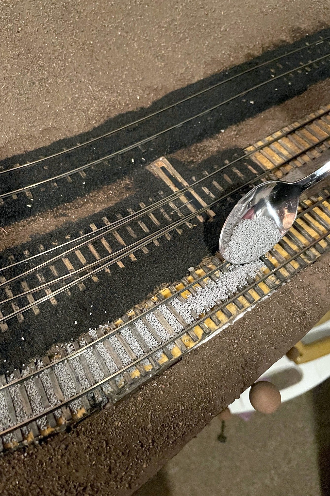
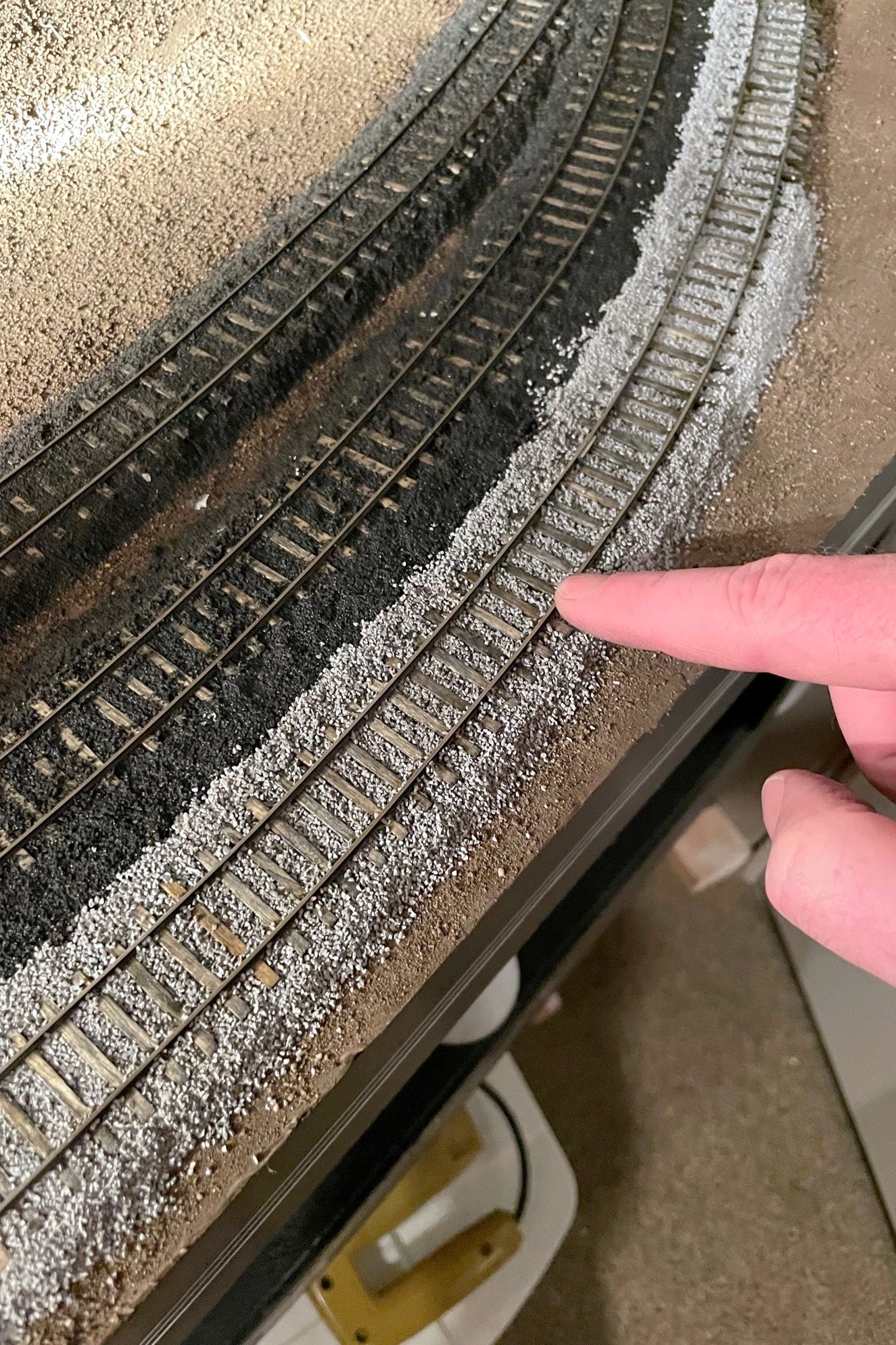
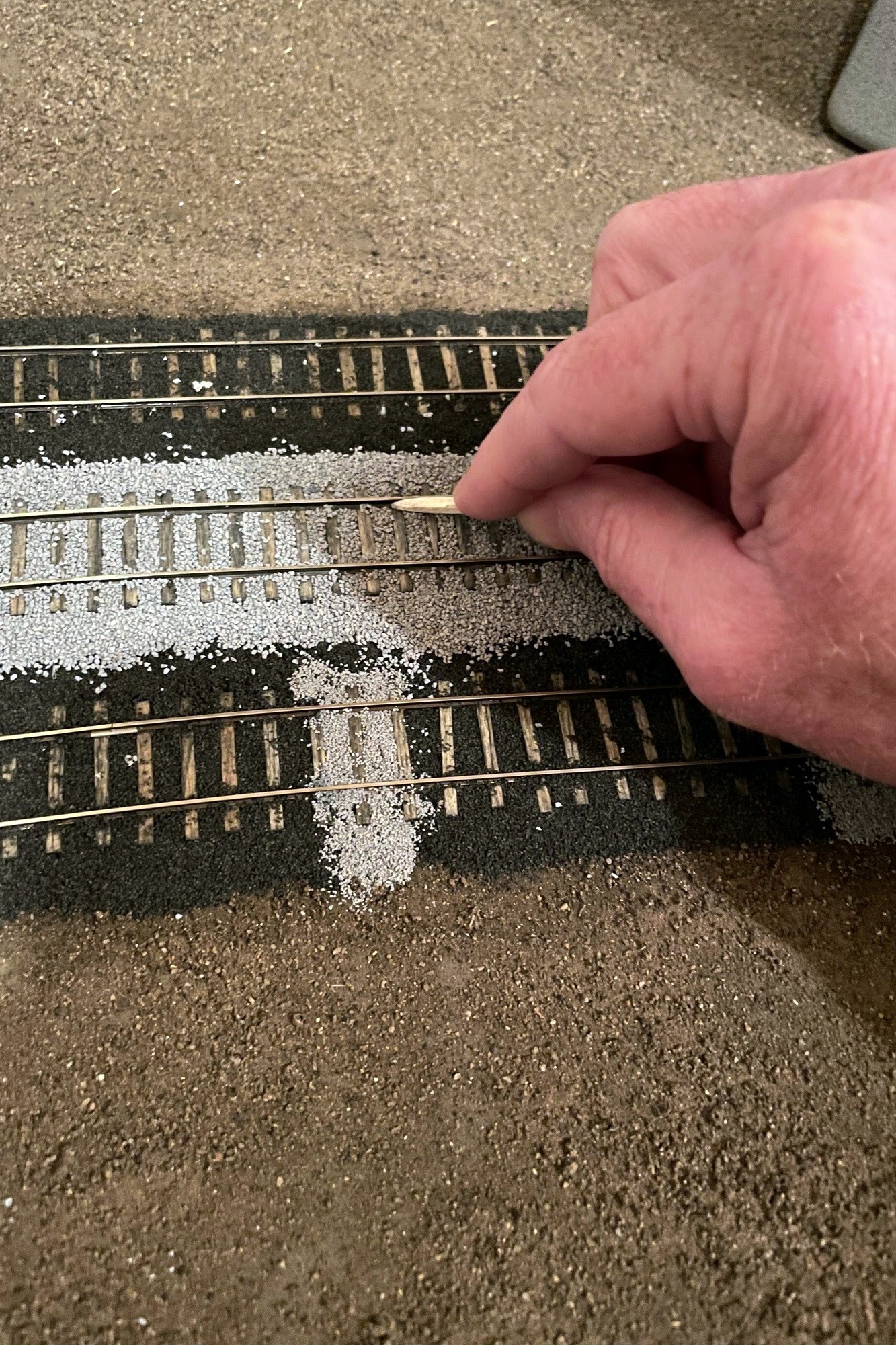
Step 1. Lay down a pile of ballast in the gauge between the railsStep 2. use a finger to spread the ballast between the ties, moving excess to the next section
I worked on the track in about 2 foot sections, usually one track at a time. If you’re doing two ballast colors, determine which ballast should be “lower” and work on that one first–for me, the cinders were replaced by ballast rock, so where they overlap, I did the cinders first. With about half-a-spoonful of ballast, I first apply it to the “gauge” (inside the rails) of the track. It takes a few tries to get a feel for how thick to lay it, but it becomes routine pretty quick. You want just enough that when you spread it the ballast fills the space in between the ties and rails with little on top of the ties and nothing on the rails. I found my finger to be an effective spreading tool, and I just rub it back and forth down the tracks, rubbing any excess ballast to open areas. Cody glues his ballast at this point, but I found it easier to lay the edge ballast first. I applied ballast to the edges by first running a bead of glue from the bottle down the side of the subroadbed and on top of the scenery–this helps the “slope” to hold better. Next I used the spoon to apply ballast inward toward the rail from about the edge of the ties until I couldn’t see the edge of the subroadbed any more. I used my finger again, first to poke the ballast under the rail a bit, then to wipe off the tops of the tie edges, and then to pat down the sloped edges until they looked smooth. I used a brush to clear off any unwanted ballast to outside the range of the glue (I vacuum it up later) and to remove any stubborn ballast from areas my finger couldn’t get to.
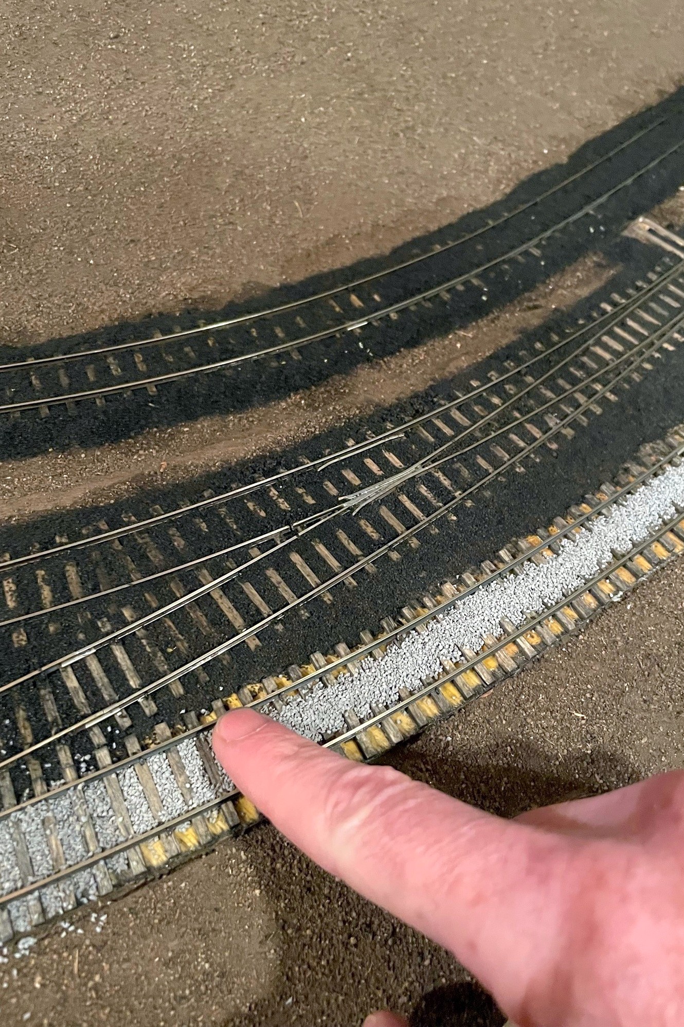
Step 3. Add ballast to the edges of the track, use a finger to work it into the ties, then use a finger to clean it off the ties and shape the slope
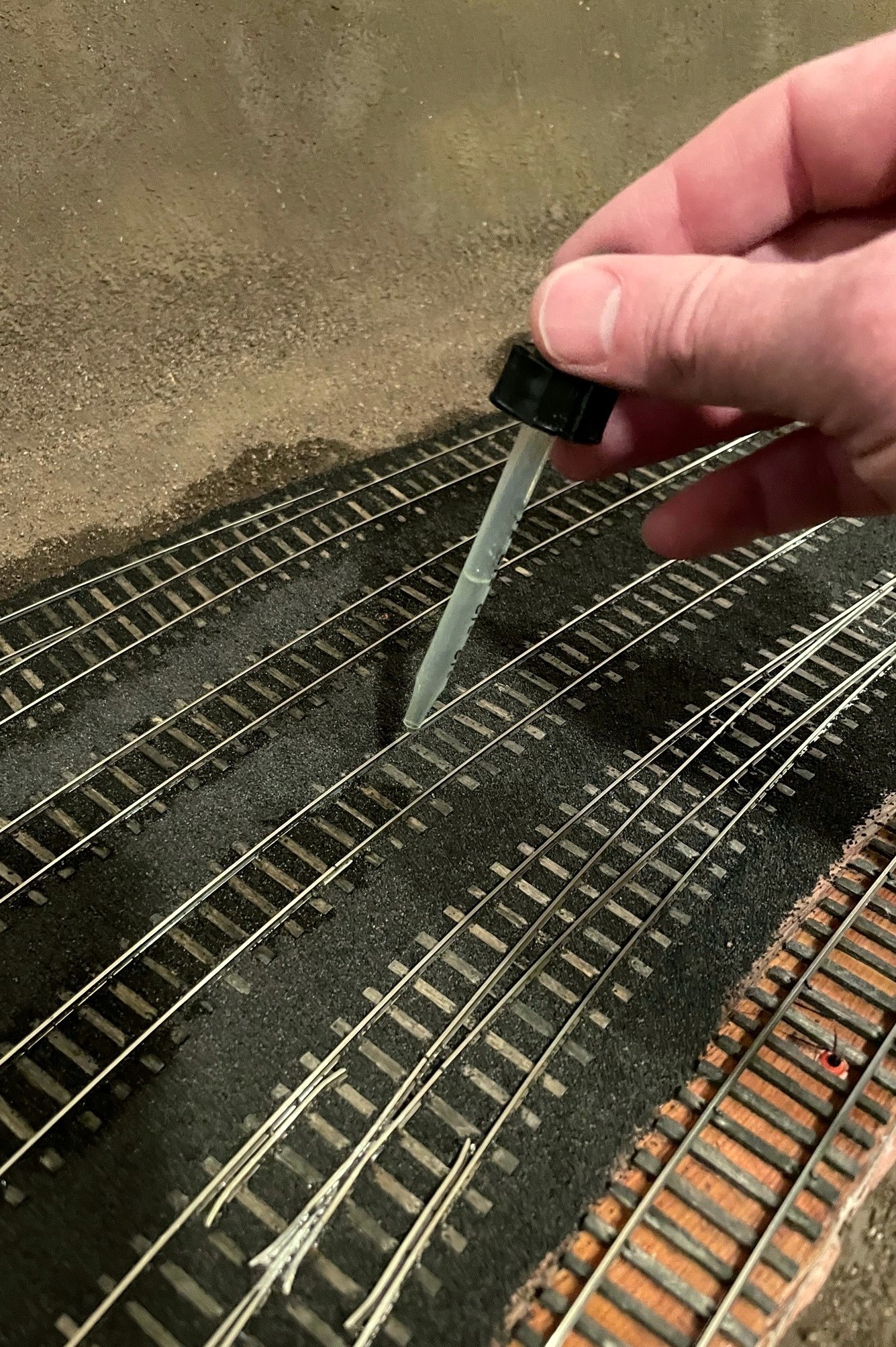
Once I’m happy with the ballast shape, I glue it down. The critical part of this process is to USE THE ALCOHOL AS A WETTING AGENT FIRST! If you just add the glue, the ballast will float (and float away) which makes a frustrating mess. You can avoid this by first saturating the ballast with an eyedropper of isopropyl alcohol–just drop until everything looks wet. I follow the alcohol wetting with the very wet glue, making sure I apply drops to every section of ballast until things were saturated and it took a couple seconds for the glue to soak in. If you drop a big glob of white glue that somehow didn’t get diluted, no worries–just dilute it with some alcohol, and it will likely settle in just fine. I wet and glued each section by starting with the gauge between the rails, then moving to the edges. I found for the edges it’s better to start the alcohol low and work up to keep things in place, and its better to start the glue high and let it work down.
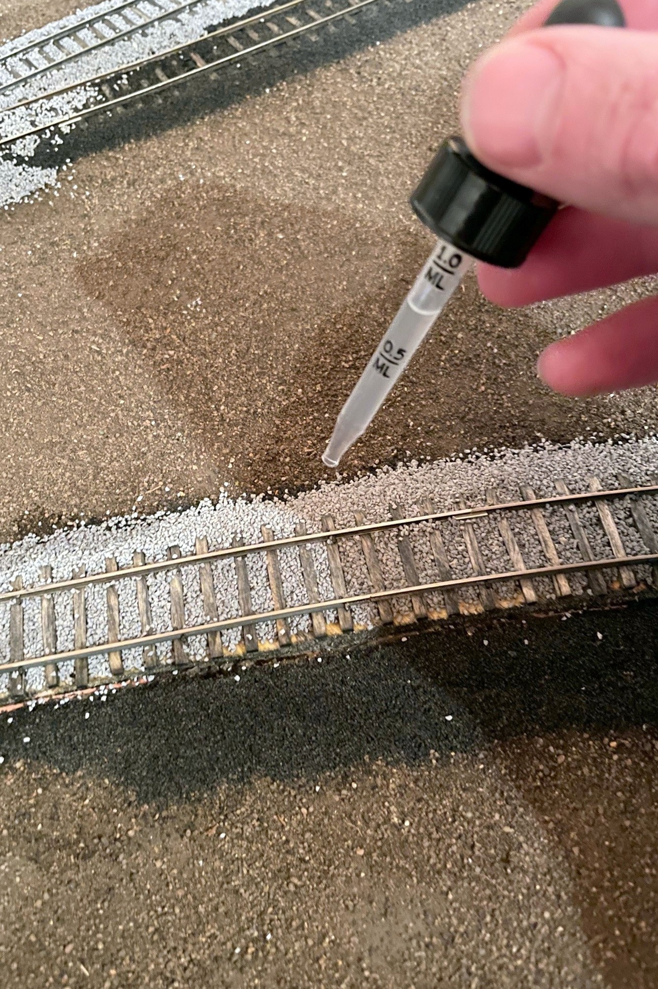
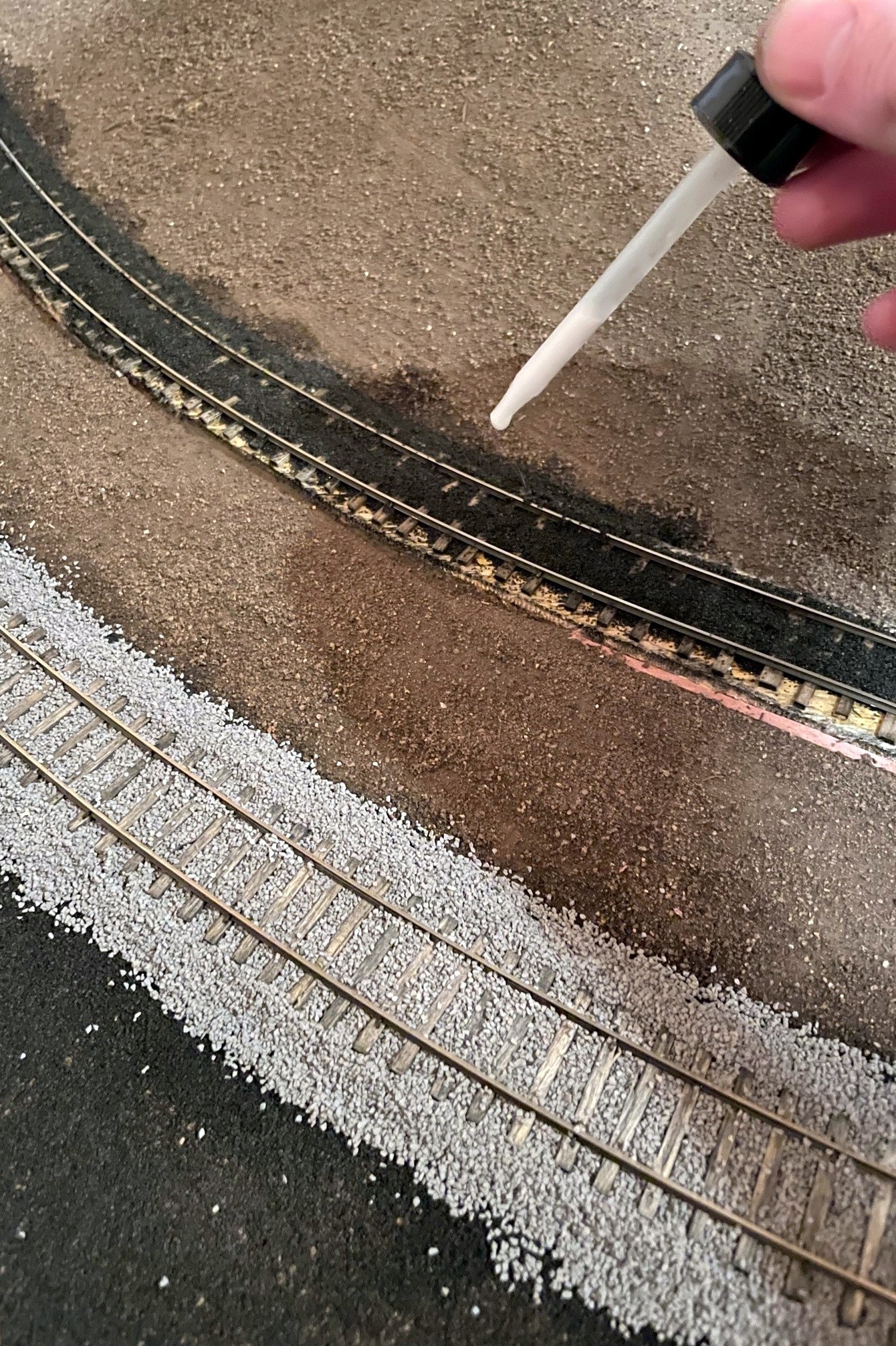
Step 4. Using a dropper, soak the ballast with isopropyl alcoholStep 5. Saturate the wet areas with wet glue
Turnouts require a bit more care, and I probably didn’t take all the care I should have… it worked out ok, but I spent a couple hours massaging my turnouts to get them working smoothly again. I spread the ballast a little less thickly between the ties to make sure the points wouldn’t catch, and I took care to avoid putting ballast in the area of the throw. No matter how careful I was, there was always some piece determined to get stuck in the throw, so I used the brush (and the occasional X-Acto blade) to fish out any offenders. I used the very wet glue sparingly in these areas, but there was still some glue that stuck to the top of the ties causing the points to stick a bit. I believe Cody’s method is to drop the glue in first, then add the ballast under the points, and I think I’ll try this next time.
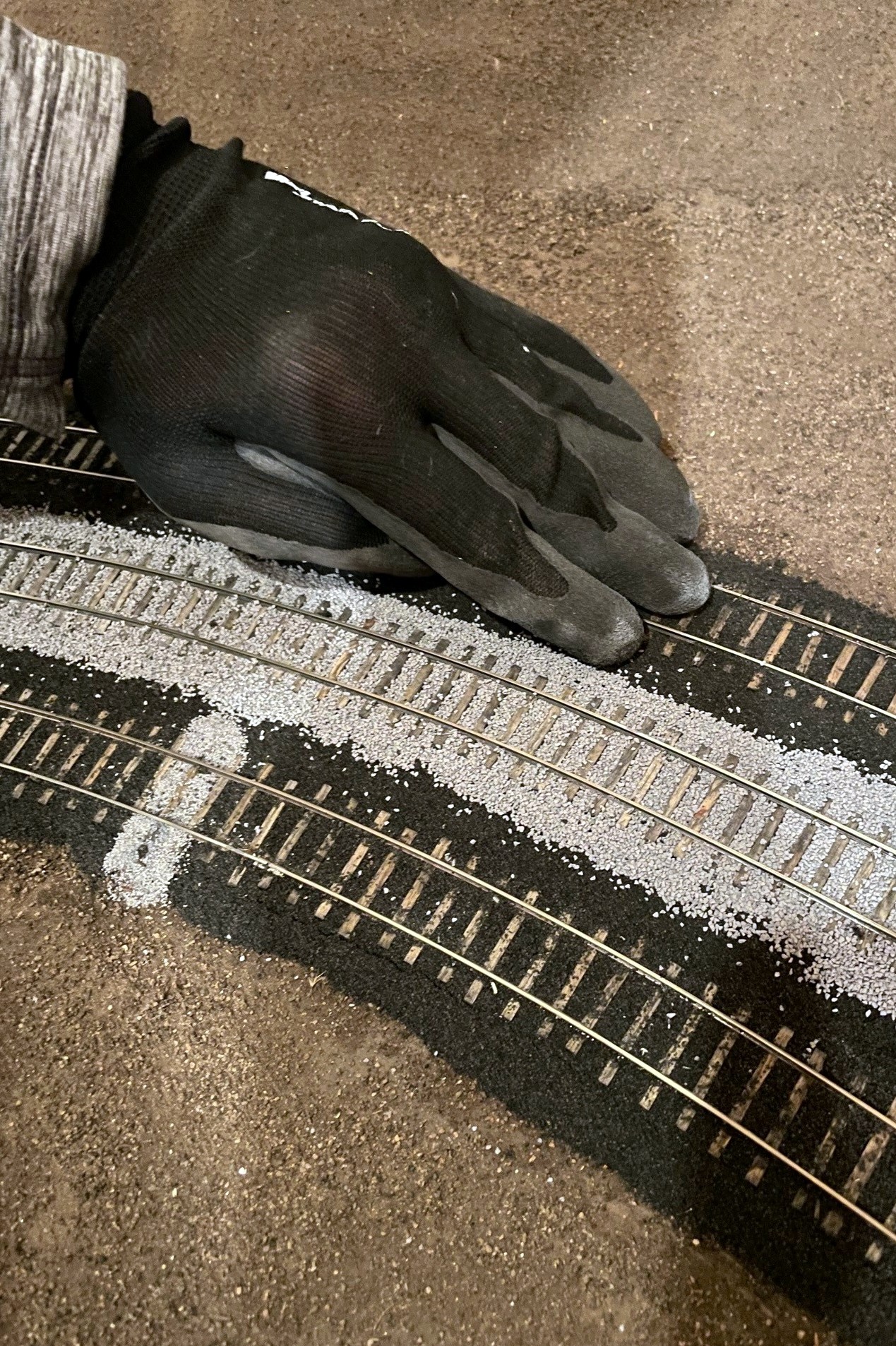
Step 6. Clean off any excess ballast–I use a work glove for thisStep 7. Clean any remaining ballast from the web of the rail–I use a combination of a matchstick and fingernails
After letting the glue dry overnight, I clean up any excess ballast. First, I use a work glove and rub it over the top of the ties and edges to knock off any obtrusive pieces. Next, I clean out the area in the web (sides) of the rail using a matchstick rubbed back-and-forth followed by a fingernail. I used a flathead screwdriver to clean out flangeways if necessary. I cleaned up any excess with a vacuum. You’ll inevitably find spots you missed with the glue, but it’s easy to just add more ballast, drop some alcohol, then drop some glue to repair.
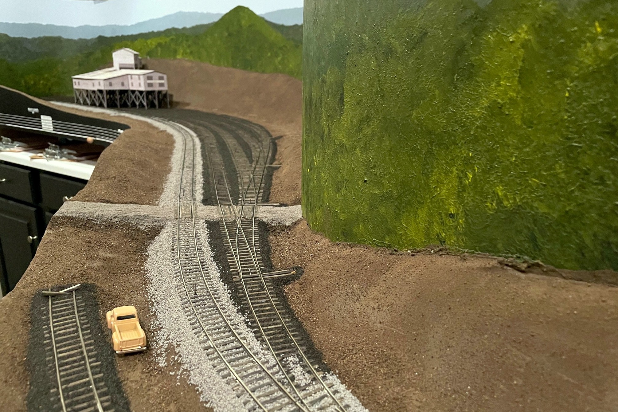
Ballast is scenery, so I also wanted it to tell a story. Because track repairs would have been made with gravel instead of cinders in my era, I picked a few spots along the cinder-ballasted yard tracks to fill with gravel (in this case, Woodland Scenics fine gray ballast) to simulate a replaced tie. I like the look! I also picked a few spots in prominent areas to lay some cinders on the scenery to go underneath the ballast rocks to show that some tracks were once cinders but had now been ballasted with rock. I also laid a thin layer of cinders in areas where I know tracks used to be, even though I don’t model them in my era. Finally, I added extra cinders to areas under tipple chutes and where locomotives sit to represent spilled coal and grime. I’m pretty happy with how these “extras” turned out, but they won’t fully tell the story until more scenery is complete.
The St Charles yard where the main is clearly visible. The gray areas on top of cinders represent tie repairs after the age of cinders
Ok, the ballasting was the last step before adding the upper deck, but you’ve heard that before… We shall see.
Here’s the finished ballast at the Mayflower tipple–the road is made from fine ballast as well
Step 1. Lay down a pile of ballast in the gauge between the rails
Step 2. use a finger to spread the ballast between the ties, moving excess to the next section
Step 3. Add ballast to the edges of the track, use a finger to work it into the ties, then use a finger to clean it off the ties and shape the slope
Step 4. Using a dropper, soak the ballast with isopropyl alcohol
Step 5. Saturate the wet areas with wet glue
Step 6. Clean off any excess ballast–I use a work glove for this
Step 7. Clean any remaining ballast from the web of the rail–I use a combination of a matchstick and fingernails
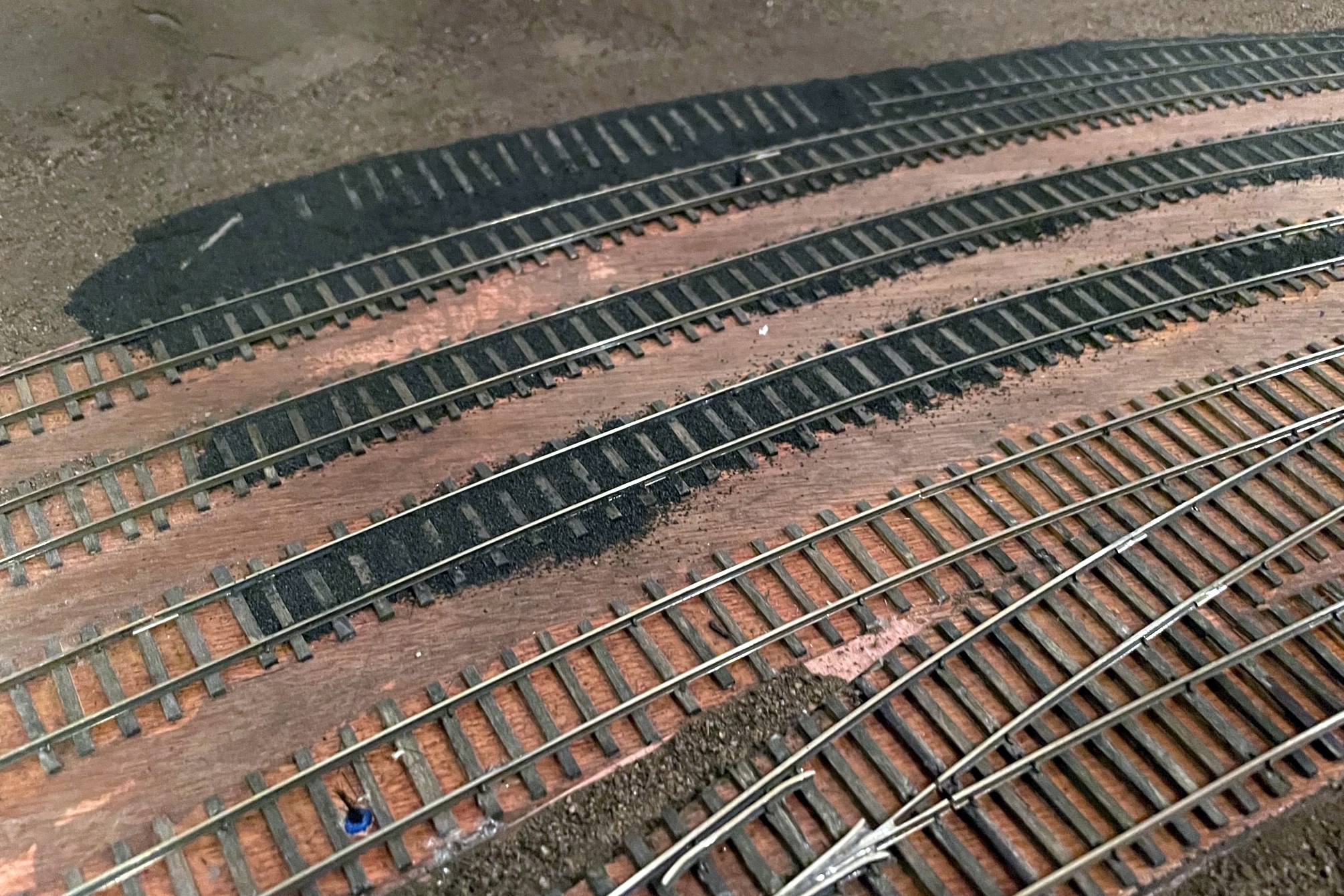
For yards, I did multiple tracks at a time, starting with the gauge, then filling in the areas between tracks
Even when working on multiple tracks at a time, I still wet and glued the gauge portion of all the tracks first
Here’s the finished ballast at the Mayflower tipple–the road is made from fine ballast as well
Transitioning from rock to cinders is done abruptly, but I sprinkle rocks to make a better transition
The St Charles yard where the main is clearly visible. The gray areas on top of cinders represent tie repairs after the age of cinders
Here’s the St Charles wye with ballast. Note the area of cinders where a track used to be
I piled more cinders on top of the rails where the engines sit to simulate grime build up
Here’s a look at last Saturday’s progress including finishing most of the lower level scenery base and painting the rest of the backdrop
I had a happy aligning of the stars on Saturday where my wife was gone for the day, I didn’t have any big “chores” to do, and I had just learned how to paint backdrops! All that combined into a day spent furiously trying to finish up the lower-level scenery forms so I could paint the rest of the lower-level backdrop. It was a good day, and I’m pretty happy with the results. I learned that the painting is my favorite part, roughing in the scenery with cardboard strips is my second favorite, and papering over the cardboard with section after section of red rosin paper is a distant third. Round 2 of backdrop painting went a little smoother than round 1 as I think I had a better grasp of the techniques, and the paint brushes seemed to work better on their second use. I liked the results of round 2 so much I went back and redid some sections of round 1.
The St Charles Local traverses the wye with the newly painted backdrop. It will soon descend through the backdrop in the corner, a hole much tougher to spot now
The scenery covers over the hidden track along the back wall that joins St Charles and the Mayflower section, so I decided to do a test run… I can now verify that I can indeed – by twisting at odd angles, reaching into small gaps, and fishing it out the last couple feet with a long string of hoppers – free a stuck train from the most remote part of my hidden track! Lesson learned–when you use hot glue for scenery, it tends to leave a lot of strings hanging down, and go figure, locomotives don’t pick up electricity so well when their wheels are covered in bits of glue string! A little wheel cleaning and some extra sweeps of the hand through the area (again at odd angles via small gaps), and trains now traverse this area nicely.
Where the two lower-level scenes transition–the backdrop on the right is lower than the left, hence less blue sky
I’ve only got one section left that still needs a backdrop and scenery forms, over the helix from staging. Painting the backdrop in the corner was the big barrier to adding this, so that will likely be the next step, and the LAST step before building upper-level benchwork… it’s getting pretty real.
Here’s where trains will leave the lower level and enter the helix to the upper level–I think the backdrop painting along with a few trees will hide the transition well
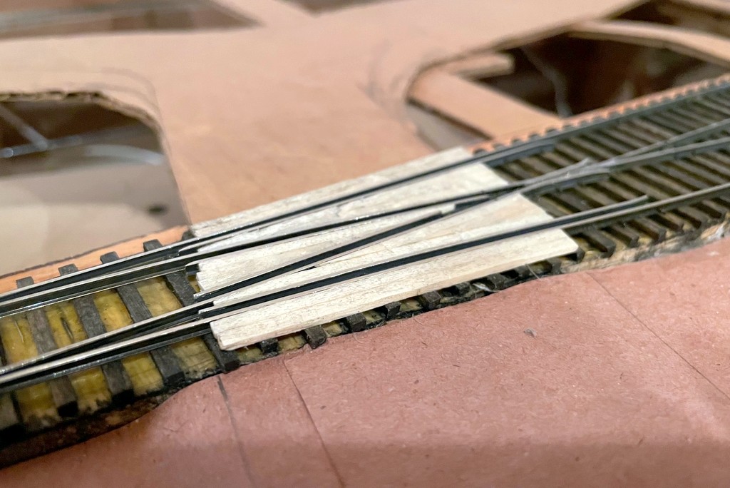
The basic scenery form is now almost done in St Charles–just some cardboard strips and red rosin paper… and lots of glueThe almost finished crossing after whittling, sanding, and scribing lines and bolts with an X-Acto blade and thumbtack
Just a quick progress update. After procrastinating and working on a semaphore, a station mock-up, and even safety signs, I’ve finally started work on the scenery again. Using the same “paper shell” method of cardboard strips, red rosin paper, and lots of hot glue, I’ve been able to get the wye in St Charles filled in with the basic land form. Of course, putting in the cardboard underlayment for the roads got me thinking about grade crossings, so I had to pause again and put in 6 grade crossings using rails and wood. Pretty simple and nothing profound, but I’m happy with the way they’re turning out. I didn’t worry about vertical height of the wood initially, only horizontal placement. I used a razor blade to whittle the wood down to rail-height level (a little tricky and scary, but effective), then used a little sandpaper and a “bright boy” track cleaner to ensure the wood doesn’t stick up and cause electrical contact issues.
That’s all for now.
The basic scenery form is now almost done in St Charles–just some cardboard strips and red rosin paper… and lots of glue
Step 1 of a complex grade crossing–adding the guard rails (extending the existing guard rails in this case)
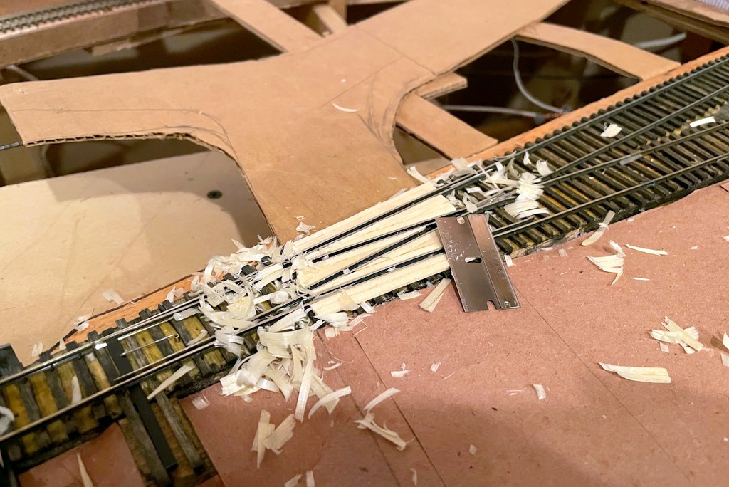
I used full size ties and wood glue to fill in between the guard rails, then used a razor to whittle everything down to rail-height
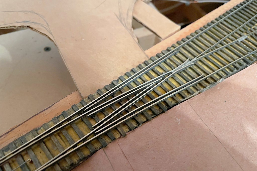
The almost finished crossing after whittling, sanding, and scribing lines and bolts with an X-Acto blade and thumbtack
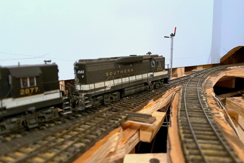
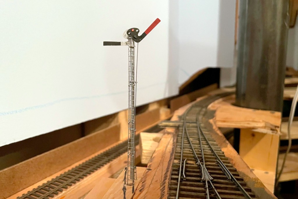
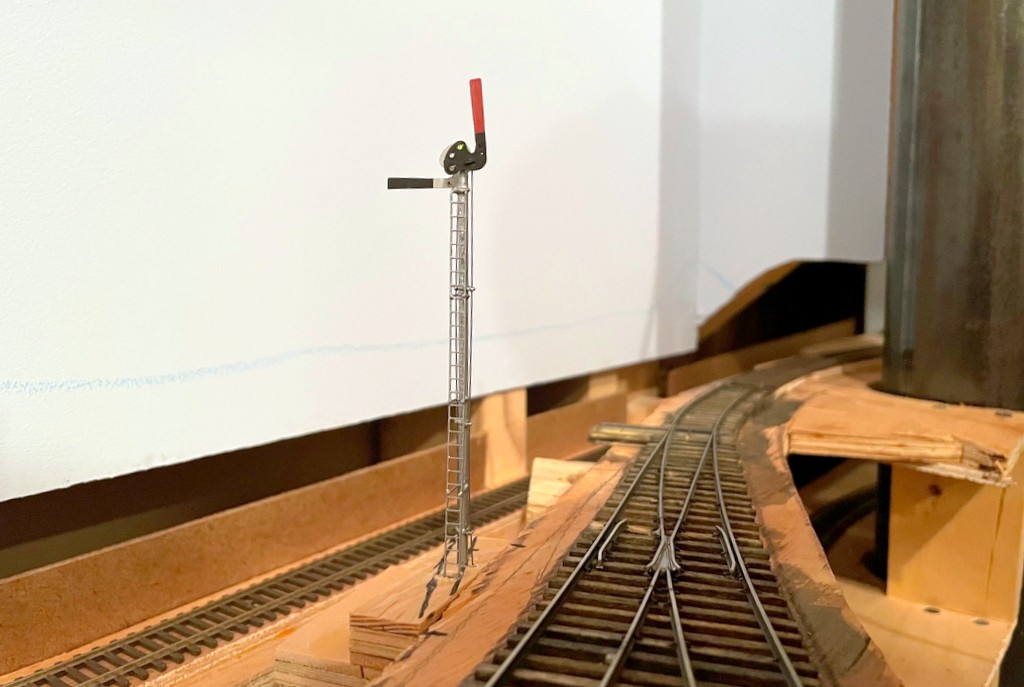
The semaphore in action indicating the St Charles Local has no orders to pick up before proceeding eastward to AppalachiaBlade down and red light indicating both east and westbound trains must stop at the station to sign for orders
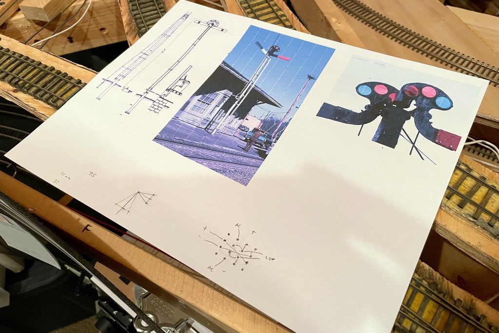
I had one major project to complete before completing the scenery base on the lower level, and that was the train order signal in St Charles. I’ve been putting this off for a couple of reasons. First, I’ve never made a full working semaphore before, so I wasn’t sure exactly what I was taking on–the dwarf semaphores I made a while ago gave me a significant head-start, but this was much more complex. Second, I don’t know exactly if the Southern used a semaphore in St Charles – or if they did where it was located – so I was hopeful my procrastination would result some evidence. Alas, I finally just had to bite the bullet and build the thing! Yes, I know there are commercially available semaphore kits, but what would be the fun in that? I’m a glutton for punishment, and I had a bunch of brass stuff laying around, so why not try to scratchbuild one?
I know with 100% certainty that the station in St. Charles had an operator who passed train orders to Southern and L&N crews working the branch. There is both photographic and timetable evidence for this. In the era I model, it was typical for a train order station to have a three-color signal of some sort indicating “red” (stop to sign for orders), “amber” (slow down to pick up orders) or “green” (no orders – proceed), and a three-position semaphore was common. On most stations, the semaphore is built right alongside the station’s office with the control levers inside the station. However, pictures of the St. Charles station clearly do NOT show an adjacent semaphore or any other type of signal. The only thing I can think is that the Baileys Creek Branch to Mayflower cut off the St. Charles main a couple hundred yards geographically south of the station, and train movements on this branch were controlled by the station–perhaps the signal was closer to this junction to allow train crews to see it an heed from both the St. Charles and Baileys Creek Branches. So, that’s what I chose to model!
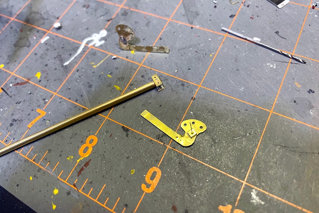
After finishing the semaphore blades, I attached a .015″ brass wire via solder and made a spacer from brass strip folded on itself. I used the same brass strip to make swivel bases for the blades on both sides of the pole
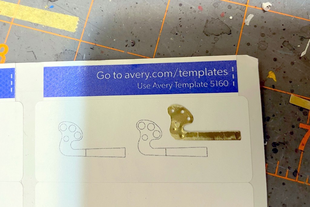
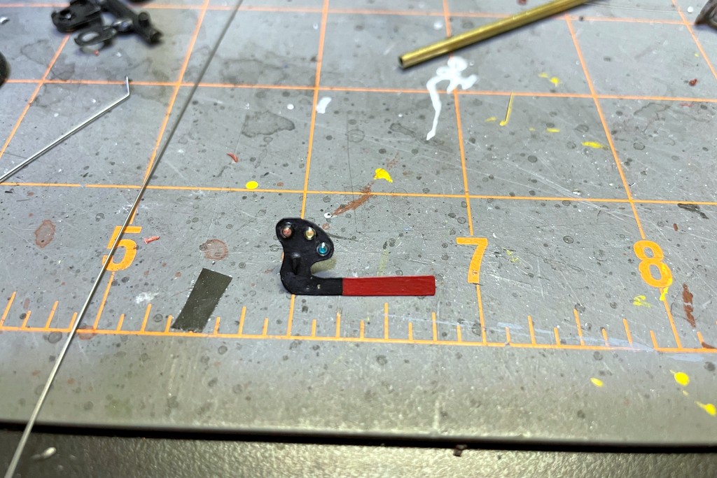
Like my dwarf semaphores controlling access to the coal branches, I wanted the semaphore to be fully operational including lights, blade movement, and fascia-mounted controls. The first job was making some semaphore blades. I did this by making an outline of an upper-quadrant blade in PowerPoint, scaling it to 1:87, and printing it onto a label. After attaching the label to some thin sheet brass, I drilled holes for the lenses, pivot point, and control rod and cut out the blade with scissors, using a file to clean things up. I soldered on the pivot rod, .015″ by bending one end, inserting it through the hole, and soldering it to the blade face. Next I added a small spacer for the blade onto the rod made from a piece of small brass bar bent on itself with a hole drilled through. I painted the blades flat black and insignia red for the blade end. The back of the blade got some silver Sharpie following pictures I’ve seen of other Southern stations. The lenses are just short pieces of fiber optic with one end melted into a round shape using a soldering iron (just hold it near the end of the fiber optic), attached with CA and colored with kids markers.
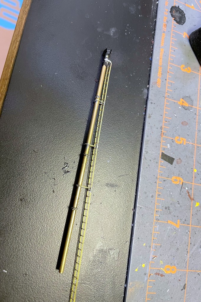
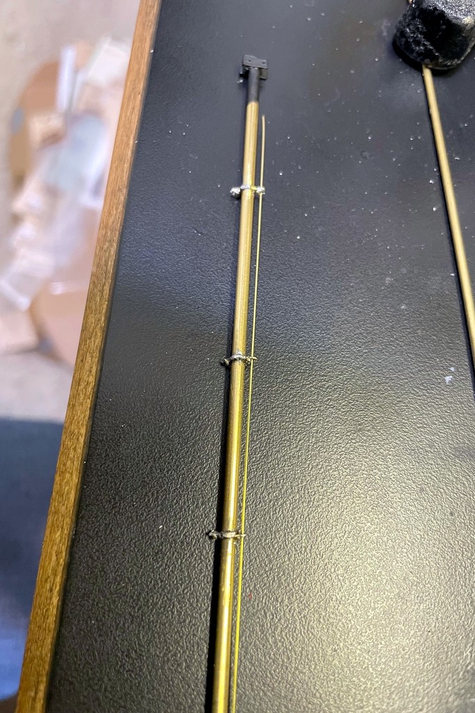
The next step was to add the brass ladder stock and connect it to the mast with U-shaped .015″ brass wire
The mast is a piece of 3/32″ brass tube. I made two mounting plates for the top out of brass bar, filed flat spots onto the tube, and attached them via solder. Next I added some guide loops for the rods that would go from the ground to the blade. I bent something resembling the shape of Saturn out of .015″ brass wire and soldered it tightly around the mast, using a semaphore mast diagram printed to scale as a guide for positioning, three guide loops total. This resulted in two U-shaped loops, one on either side of the mast. I finished the loops by soldering a small piece of wire across each U to make a smaller hole to the outside away from the mast. My soldering skills are not great, so this was a lot of ugly blobs until I took a file and cleaned things up. I added a piece of brass ladder stock by connecting it to the top with solder, bending it, and making U-shaped supports out of .015″ brass wire which I soldered into place in three locations and cleaned up. I painted the mast assembly flat black and then used a combination of silver Sharpie and silver paint to finish it.
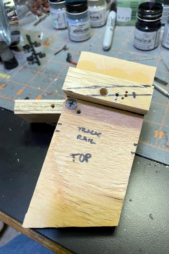
Now I was ready to put the blades onto the mast. I fashioned some control rods from .015″ steel music wire, inserted them into the blade holes, and ran them down the guide loops on each side. After inserting the blade pivots into the mounting plate, I bent the brass rod 90 degrees to hold each blade in place while allowing it to pivot freely. I made the base from scraps of plywood (see pictures) and drilled a 3/32″ hole for the mast, two adjacent 1/16″ holes which I lined with 1/16″ brass tubing for the control rods, and a larger hole for the ladder to slide into. I press fit the mast into the holes with the rods going through their brass tubes. Then I ran a piece of fiber optic cable down the tube. I first tried to file one end of the fiber optic at an angle to get it to shine through the blade lenses, but this didn’t work well. I ended up holding the fiber optic over a spare piece of 3/32″ brass tube which I heated with a soldering iron. When the tube got hot, the fiber optic bent itself over the tube in a perfect curve which still conducted light well. A little more heat to make a rounded lens at the end, and I had my “light” for the blades.
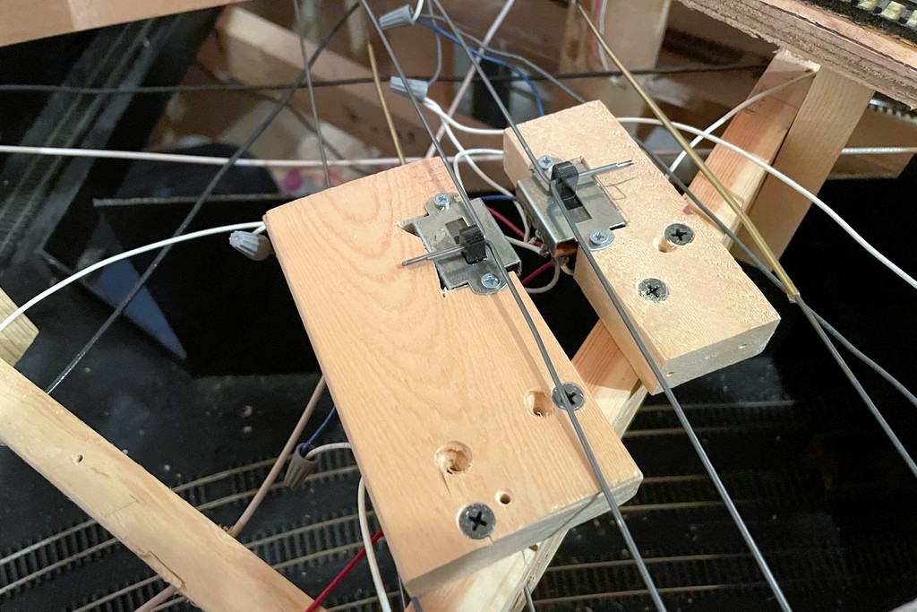
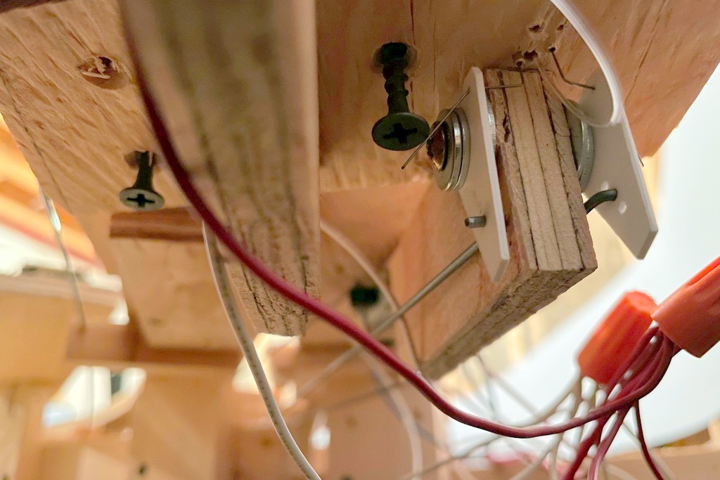
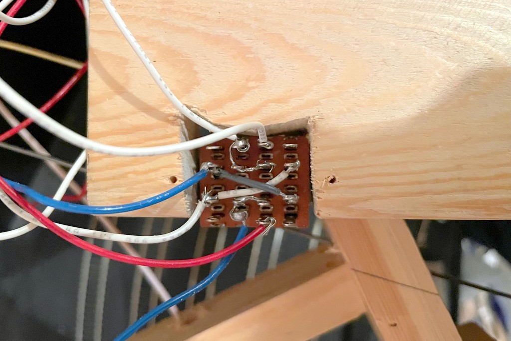
Here are the mechanisms made from 3-way slide switches. Not only do the switches route power to the bi-color LEDs, it also connects the lever to the signal mechanically and provides the detents for movement
I wanted to use .062″ steel music wire (the same stuff I use for manual turnout controls) for the fascia-mounted control rods, so I crafted two triangular levers out of thick styrene hinged at one corner to convert the horizontal control rod movement into vertical movement for the blade control rods. I covered this in some detail with the dwarf semaphores, so I won’t cover it again here. With the mechanism in place, I mounted the base and semaphore assembly in place on the layout. Next, I worked on the control rods made from 36″ pieces of .062″ steel music wire. Where they would cross through benchwork, I drilled 2/32″ holes and lined them with brass tubing. I was able to get a pretty good bend in the control rod without it kinking this way.
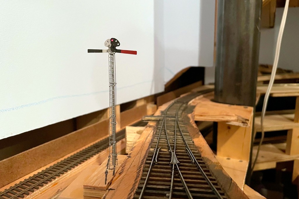
Here’s the finished semaphore from levers and lights to the blades in the background
The heart of the control rod mechanism is a 3-way slide switch. I bought a handful of these for the dwarf semaphores because of their longer throw, but it turns out they were exactly what I needed to control both the throw and the lights for the full semaphore. I’m using 2-lead, bi-color red/green LEDs for the lights. Controlling the red and green is easy enough with DC and crossing the +/- leads on two of the poles on the switch to get the red and green on the end throws of the switch. For the amber, I wanted to use the AC current from my track power. It took a bit of thinking through the use of the 16 leads (it’s a 4-pole slide) to figure out how to route both AC and DC power to the same LED without ever crossing the streams, but the arrangement seen hand-drawn on my cheat sheet (see gallery below) works well. I secured the rods to the semaphore to the slide switch by bending them 90 degrees and inserting them into a hole drilled through the switch control. A second rod inserted through a second hole in the switch control was run through a piece of 3/32″ brass tubing to the front of the fascia where I capped it off with a wood ball (smaller than the ones I use for switch controls so operators can tell the difference).
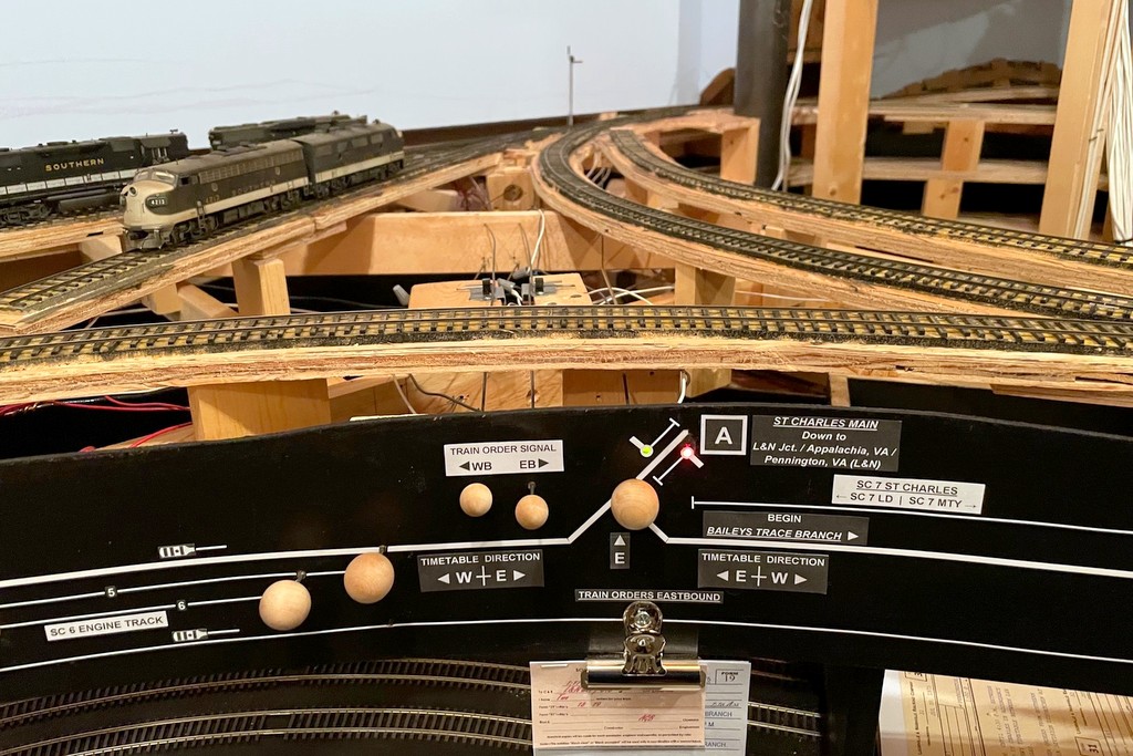
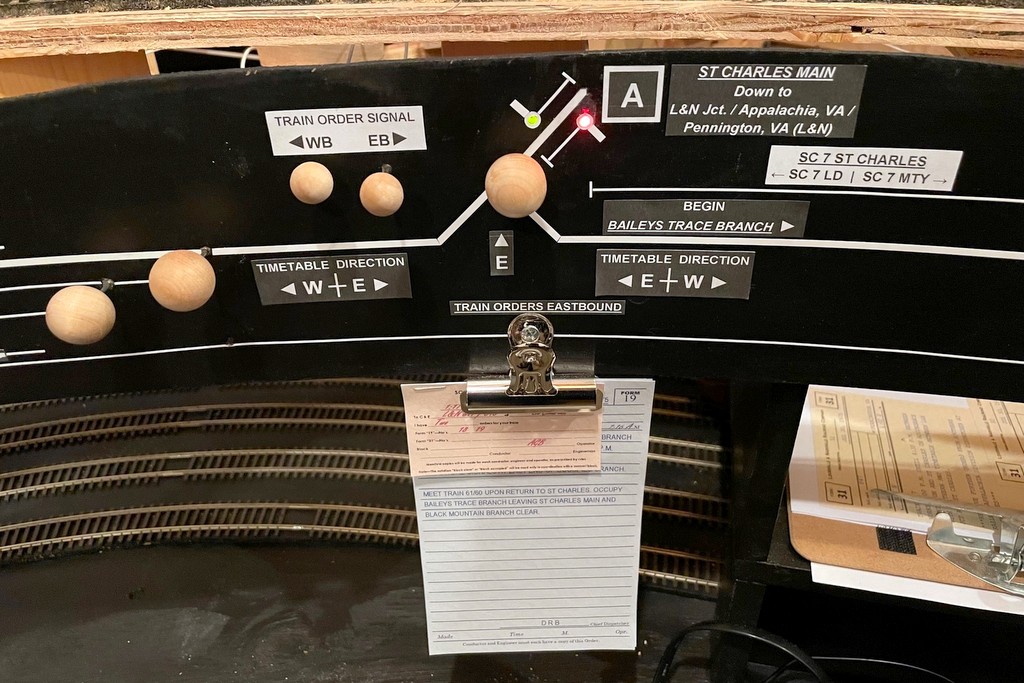
The final step was to run LEDs from both switch mechanisms to the fascia where I used stick-on letters and graphic tape to make a little drawing of a semaphore in each direction alongside the track diagram–the operators can look on the fascia to see the color indication if they don’t want to use (or don’t understand) the blade positions on the layout. Finally, I added a second clip to hold orders under the fascia so that the old clip is now “train orders westbound” and the new clip is “train orders eastbound.” So far I’m really happy with how the semaphore looks and now it operates, and it was really fun to build. I know it will add yet another aspect of prototypical operations to the layout as crews now have to read signals to see whether or not they need to pick up orders.
I made a diagram of a semaphore blade in Microsoft PowerPoint then printed it in HO scale onto a label. This made it easy to attach it to the sheet brass, drill holes, and cut it out with scissors
After finishing the semaphore blades, I attached a .015″ brass wire via solder and made a spacer from brass strip folded on itself. I used the same brass strip to make swivel bases for the blades on both sides of the pole
One of the finished blades painted black and red with no stripe per Southern custom. The lenses are short pieces of fiber optic with one end melted round by holding it close to a soldering iron. The color is just marker
I made guides for the blade control rods using .015″ brass wire bent into a “flat Saturn” shape around the mast. The control rod is .015″ steel music wire
The next step was to add the brass ladder stock and connect it to the mast with U-shaped .015″ brass wire
The base plate is simple. Under the signal is a second layer of plywood to get the signal to track level. Holes for the mast, rod guides and ladder are in the middle (the right-hand holes are mistakes). The plywood fin will support the levers to connect the manual control rods to the rods going up to the blades
Here’s where the lever rods meet the rods going up to the blades. The multiple holes in the styrene allow the rod to be repositioned for more or less throw (I ended up using the top hole on both to get more throw)
Blade down and red light indicating both east and westbound trains must stop at the station to sign for orders
Blade halfway and amber light indicating the eastbound train should slow to pick up orders (handed up by the operator) but doesn’t need to stop and sign for them
Blade up and green light indicating no orders for the eastbound train
Here’s the little cheat sheet I made up. I scaled the blueprint to HO and used the sheet to plot my throw and my wiring for the 3-way slide switch
This is the finished wiring of the 3-way slide switch. The ends connect to DC for the red and green colors of the bi-color LED. The middle attaches to AC (DCC track power) for the amber (rapidly flickering red and green)
Here are the mechanisms made from 3-way slide switches. Not only do the switches route power to the bi-color LEDs, it also connects the lever to the signal mechanically and provides the detents for movement
Here’s the fascia end of the semaphore including levers (WB in, EB out), indicator lights along the track diagram, and the clip for the orders which necessitate the signal
Here’s the finished semaphore from levers and lights to the blades in the background
The semaphore in action indicating the St Charles Local has no orders to pick up before proceeding eastward to Appalachia
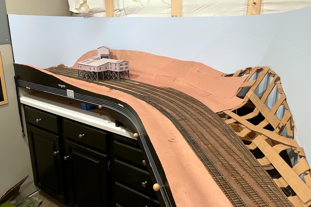
The first scenery forms are in place at Mayflower using Howard Zane’s paper shell method
So there are two reasons why I’ve been working on so many models lately. First, I enjoy building models. Secondly, I’ll admit that I’d hit a major mental block with the layout’s progress because I needed to work on the basic scenery for the lower deck before adding the benchwork for the upper deck. I could retrofit the scenery, but I figured it was worth it to add it now to save myself about 260 lumps on the head trying to install it under the upper-deck benchwork. This last week I finally got up enough gumption to jump into the deep end and start the scenery!
The first step is to draw out the line where the scenery meets the backdrop and glue a cardboard strip along the line
Ever since I read his article in the Jan 2007 Railroad Model Craftsman, I knew I wanted to use Howard Zane’s “paper shell” scenery technique. For mountainous ground that’s mostly going to be covered by trees and the occasional rock casting, this method is extremely simple and uses easy-to-find and cheap materials including cardboard, hot glue, red rosin paper (available for under $20 for a 3′ x 167′ roll at home improvement stores), and white glue. I won’t go into his whole technique, but you can see from the photos that it’s essentially outlining the hills on the backdrop with a cardboard strip, building a lattice of the basic landform from strips of cardboard, and covering the lattice with small patches of rosin paper. The next step (which I haven’t started yet) is to cover everything with a thick layer of white glue to smooth it out and give it stiffness.
Step 2 is to make a lattice of cardboard strips. I bent them and softened them before installing them with hot glue to get more natural bends
I’m starting with Mayflower and working around to St. Charles. Some would recommend a much steeper terrain so the majority of the background is hills and trees, but I’ve opted to go with a more natural angle between 30-50 degrees slope. This means my backdrops will need to be painted really well since the transition from scenery to backdrop will be very visible. If you look closely you can see where I’ve drawn in the ridge line near the top of the backdrop. I don’t know how to paint yet, so what could go wrong? We’ll see how that goes soon enough!
So far this has been a time-consuming but enjoyable project, and I’m very happy with the paper shell method. I’m learning little tricks as I go which will make it go faster as I gain more experience, but it’s great to start seeing things take a shape other than plywood and dimensional lumber!
Step 3 is to hot glue small sections of red rosin paper to the cardboard lattice
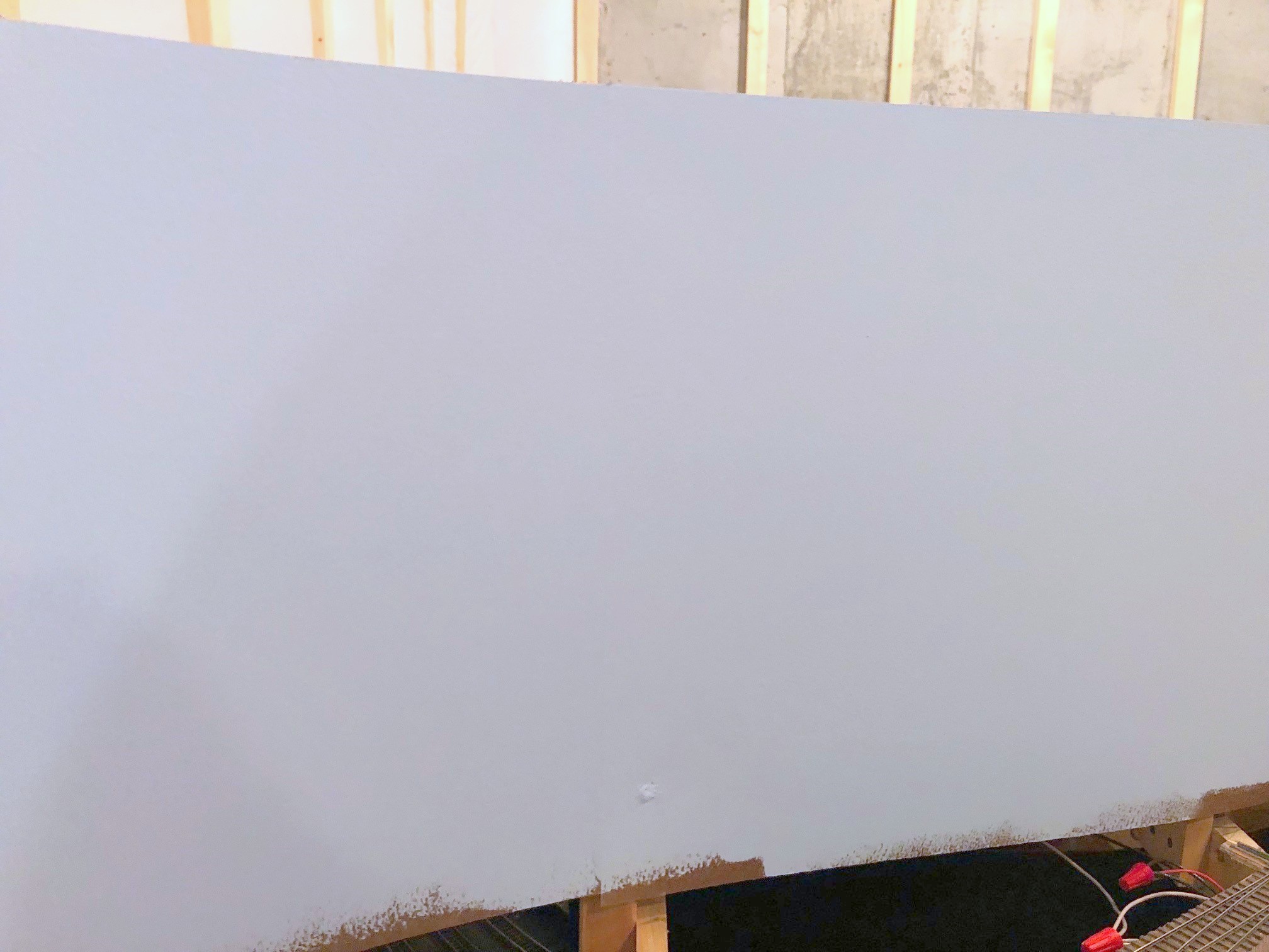
There is now a pale blue sky in St Charles, VA! This past week has been “backdrop week” on the layout, and today I finished sanding and painting the blue color on the backdrop. It’s amazing what a difference the backdrop makes in giving shape to the scenes. This is also a big step because it’s one step further than I got with my last layout before I had to tear it down–it’s good to surpass the progress of the previous effort.
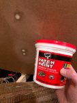
There’s a vertical seam between two Masonite panels in the middle of this pick and an upper screw–can you find them?
The backdrop, like the fascia, is 1/8″ Masonite (or “hardboard” at some stores). I know a lot of modelers like Masonite because of its smoothness and flexibility, but over the years I’ve heard one repeated complaint: “it’s nearly impossible to fill holes and cover seams because nothing will stick to it.” If you’re worried about this, worry no more! I find that lightweight spackling compound (I use DAP Patch-N-Paint) works perfectly on Masonite. A couple of tips. First, make sure you countersink the screw holes so the screw heads are at least 1/32″ below the face of the Masonite to give enough depth for the spackle to work–this is tough to do without going through the 1/8″ board, but don’t worry if you have to patch an extra hole. Next, I apply a layer of the spackle over the screws and across any joints with a plastic putty knife to avoid scratching the Masonite. I clean it up a little with the knife, but messy is ok. After it dries for about 1-2 hours, I use a damp washcloth to scrub off the excess spackle. This usually leaves a bit of a depression in the holes and seams, so I put on a second layer of spackle. After this completely dries, I sand it with 150-grit sandpaper until it’s even with the Masonite surface and wipe it once again with a damp washcloth. Once painted, I have to look very carefully to see the seams, and the screw holes all but disappear.
For the color, I wanted a very light sky blue, enough to look blue but that kind of whitish and hazy blue on the horizon. I stood in Home Depot for 20 minutes with pictures of Appalachian scenes on my phone comparing the color to all the options Behr had to offer. I finally decided on this color in a flat finish (Behr calls it “After Rain”), and I’m pretty happy with it. If anything it’s a little more blue than I’d hoped, but the hue looks pretty natural, and it’s not too dark. Two coats with a roller gave the backdrop a nice even look. The backdrops are all ready to support some scenery forms now.
I must say, I’m going to miss taking pictures of the Mayflower Tipple mock-up with a nice white plastic insulation blanket as the backdrop… ok, no I’m not.
Lower level backdrop ready for paint
Lightweight spackling compound is great for patching Masonite board
1/8″ Masonite is very flexible and can be bent into pretty tight corners
I decided on this color because it’s very light and makes a hazy looking sky blue
Painted backdrop wrapping around the helix
There’s a vertical seam between two Masonite panels in the middle of this pick and an upper screw–can you find them?
Goodbye insulation background for the Mayflower tipple mock-up
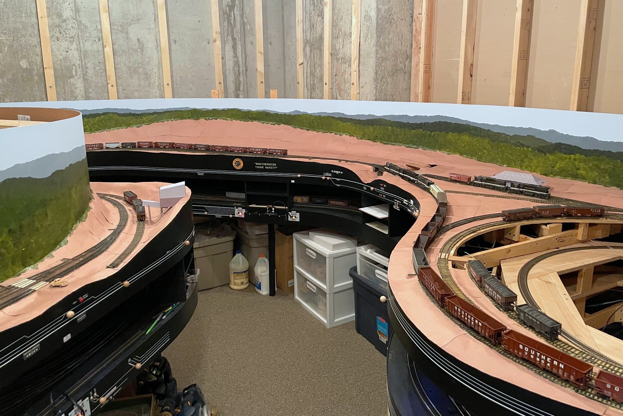
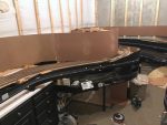
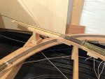
The finished helix! From here it will traverse the concrete wall in the background before emerging at Turners Siding
Reached another milestone yesterday–the main helix between the main and upper levels is now complete! I have track reaching to 58″ off the floor. Like the helix between staging and the main level, I used what I call the “double pinwheel” method of building a helix (click here for a full write up on the double pinwheel helix). It requires only straight-line cuts, it’s very forgiving of non-precise cuts, and it’s rock solid.
The helix joins the town of St Charles to the towns of Turners Siding, Kemmergem, Monarch and Benedict on the upper level. The grade (3%) starts at the RR-west end of St Charles yard and continues up three turns of the helix. There will be another 15 feet of hidden track before the line emerges, so that’s effectively a fourth turn’s worth of elevation gain after the helix. Of course, when I built the base supports for the helix, I miscalculated something that had the initial grade into the helix closer to 4%. At first I was like, “well, maybe it will work.” I test ran a few locomotives up the first loop (all I had constructed upon discovery), and while my lightest locomotive could still pull 11-12 cars up the grade, I finally wised up and decided to fix it before it became unfixable. After dropping to 3% (lowering all the supports by 3/4″), the lightest locomotive could again haul 14 cars and a cab from a dead stop up the grade, the same limit as the helix from staging. I’m sure I will be glad I made this adjustment in the future! Measure twice, cut once… thankfully it just required loosening and reattaching some screws and only a few new cuts of supports to fix it.
It will be a little while now before I start the upper-level benchwork, but finishing the helix will allow me to install the lower-level backdrop, so the beautiful insulation pads will no longer be visible on the main level. I know that will be a big disappointment to many of you who feel the insulation just adds an extra layer of realism… ok, enough sarcasm. Building helixes isn’t fun for many modelers (including me), so I’m very glad this portion of the layout is now complete!
The first level of the helix installed before discovering I needed to lower it 3/4″
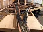
Continuing up the helix using the double pinwheel method
Helix almost complete
The finished helix! From here it will traverse the concrete wall in the background before emerging at Turners Siding
Lower level fascia complete and awaiting a few labelsPush rods can indeed be used for distant switches (48″ here) if properly guided and reinforced
This week’s project was completing the fascia for the lower level. I love the look of the curved black fascia and track diagrams. I’ve detailed fascia elsewhere, so I’ll stick to what’s unique here. While the switch mechanisms can be partially installed prior to fascia, it takes the facia being in-place to install the manual switch control knobs and push rods. While most of the mechanisms were pretty basic, there are three switches more than 30″ from the fascia on the “RR east” end of St Charles wye where the tracks emerge from the helix and staging. I wasn’t sure if I’d be able to use the push rods for long distances, especially since two of the switches are beyond 36″, the length of the .062″ steel rods I use. The trick with the push rods is the longer they are, the more they tend to flex and bend (and, in turn, not throw your switch mechanisms). This can be partially rectified by using additional brass tube guides in wooden blocks along the rod’s path, about every 12-15″ or so. That was good enough for the first mechanism that was <36″ from the fascia.
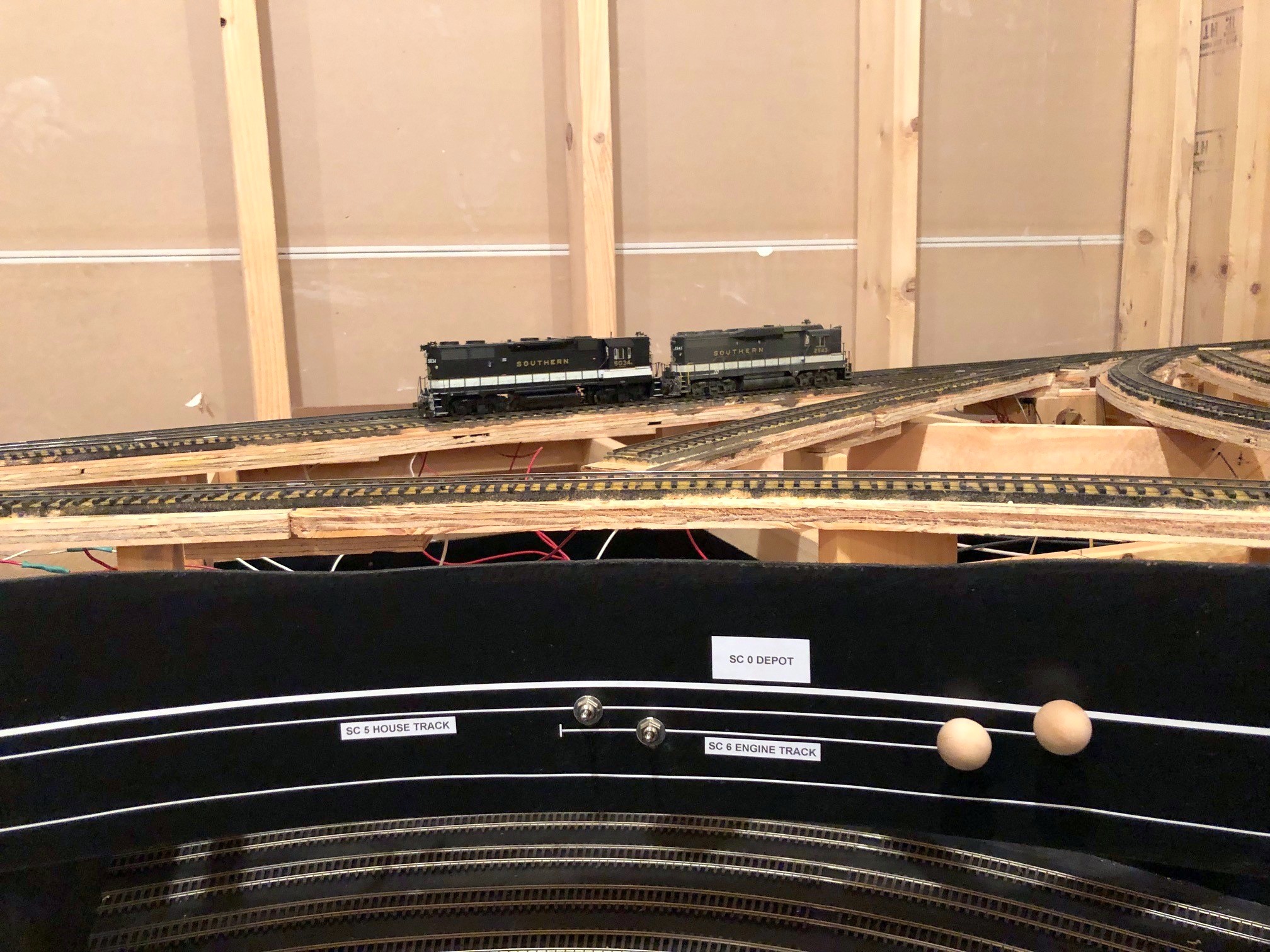
St Charles wye has two insulated tracks where engines might tie up
For the longer rods, I decided to try connecting 2 steel rods using a 6″ piece of 3/32″ brass tubing and Gorilla Glue. I use the Gorilla Glue to attach the wooden knobs to the steel rods, so I know it’s got at least SOME game with metal. Since these rods will be hidden by scenery, I decided not to trust glue alone, so I lightly bent both the tube and steel wire about 1″ from the end of the tube on both sides–if there’s one thing I’ve learned, even a slightly bent .062″ wire does NOT want to pull through a 3/32″ piece of brass tube! Once I added the bends, the mechanism is solid as a rock! I’ve now verified that the manual push-rod controls are viable to at least 48″ from the fascia–not bad at all, and all remaining switch controls should be well under this length.
Another unique feature of the St Charles fascia is the addition of two SPST toggle switches that isolate two of the tracks from the wiring bus. A while ago, I detailed how I did something similar for my staging tracks so I could easily silence sound locomotives when they’re not actively involved in the operations. St Charles was often home to a mine run, so the pair of mine-run engines hung out on either the “house track” or aptly named “engine track” adjacent to the depot. Since these are the only tracks on the levels with scenery where I anticipate parking locomotives, I decided to give them the same insulation and toggle setup as the staging tracks. While I will likely rarely use these, I figured it’s SO much simpler to add them now than decide I need them after-the-fact.
L&N RS3 100 takes a trip around the wye at St CharlesCompleted St Charles yard tracks
Hit a major milestone yesterday: the lower level tracks are complete! I completed the first scene, the end of the line at the Mayflower tipple, several months ago, and the last few months I’ve been working on the long scene at St Charles. St Charles – the branch’s namesake – was home to a wye, a depot, a couple small tipples, and a three-track “yard.” St Charles was also home to a mine run when the tipples were busy, so this is the central scene on the layout. All told, the St Charles scene is about 26 linear feet long and required 14 hand-laid switches (about 1/2 of them curved) and a couple of bridges.
Electrically, I made the entire Mayflower branch an auto-reversing zone for the wye. Can I just say the On-Guard AR solid-state DCC auto-reversers are awesome? The switching of polarity on the wye is absolutely seamless and unnoticeable–I highly recommend them! I also isolated a single rail of both the “house track” and “engine track” in the middle of the wye and will place a switch on the fascia. This will allow me to turn the power off to the two tracks that would hold idling power in case any sound locomotives get annoying. Next step is fascia and switch controls.
This is the current “end of track” just above the St Charles yard
L&N RS3 100 takes a trip around the wye at St Charles