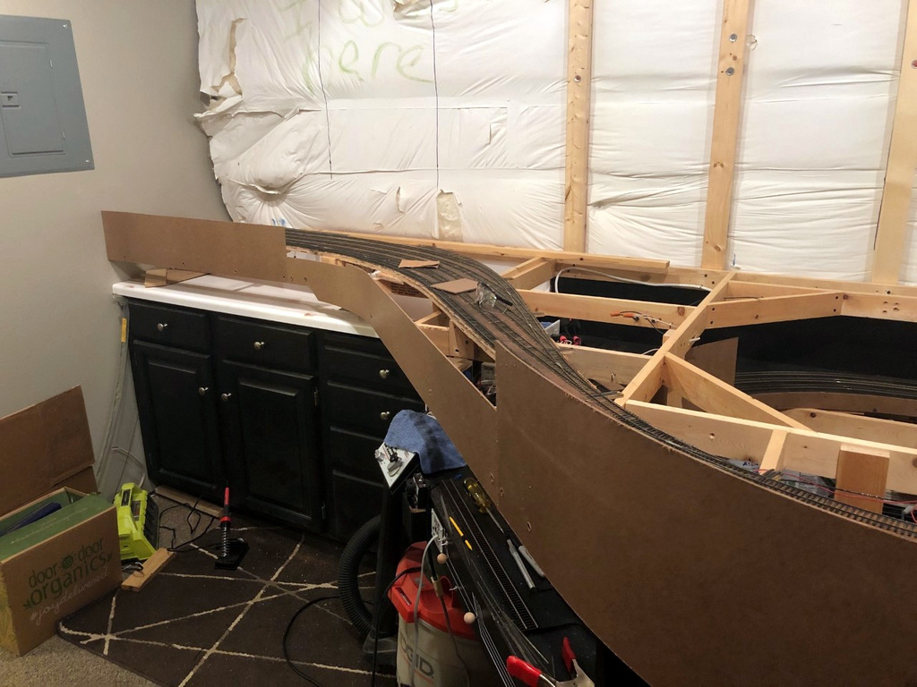
Working on the fascia is very mundane and unexciting, but as a human factors engineer by education, I take my fascia very seriously! On most layouts, the fascia is the primary interface between operators and the layout. It’s often where we place controls and place names, and it’s also a blank canvas we can use to help our operators better understand the scene they’re interacting with. Like many who perform switching operations on their layouts, I like to use the fascia to help operators understand as much as possible about towns, tracks and industries to aid in making their switching moves.
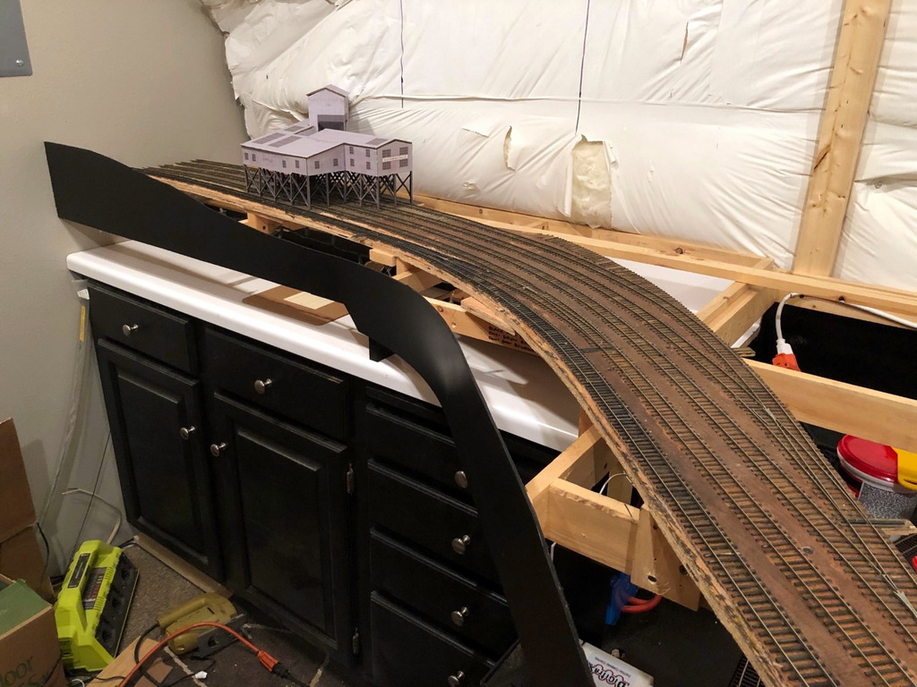
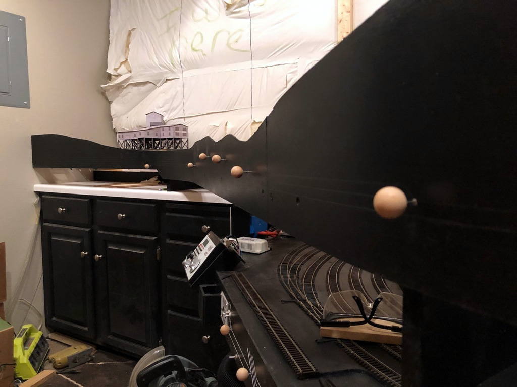
As far as construction goes, my fascia is just sheet Masonite fastened to the benchwork with drywall screws. I cut it in thick strips that will account for all the vertical scenery contours along the front edge. Where there are noticeable gaps or indentations from the screws, I touch things up with lightweight spackling compound and wipe it smooth with a damp cloth after letting it harden for about an hour–this saves a lot of time sanding later. Then I draw in the ground contour with a pencil and cut it with a jigsaw. A little black paint, and things are ready for the operator features.
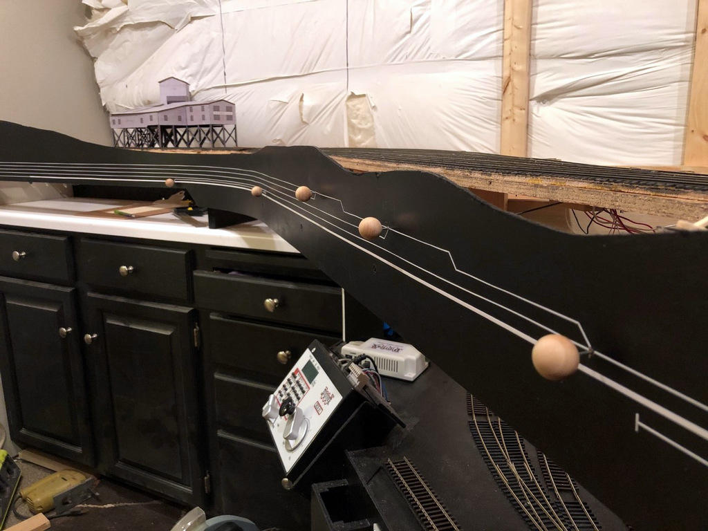
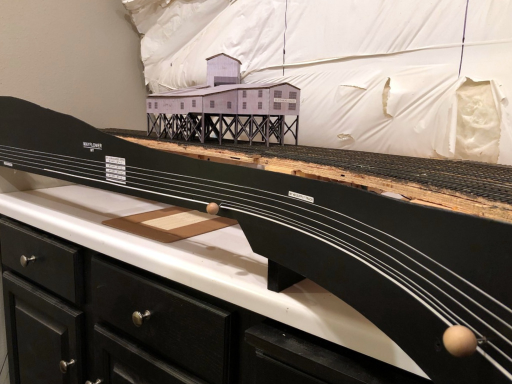
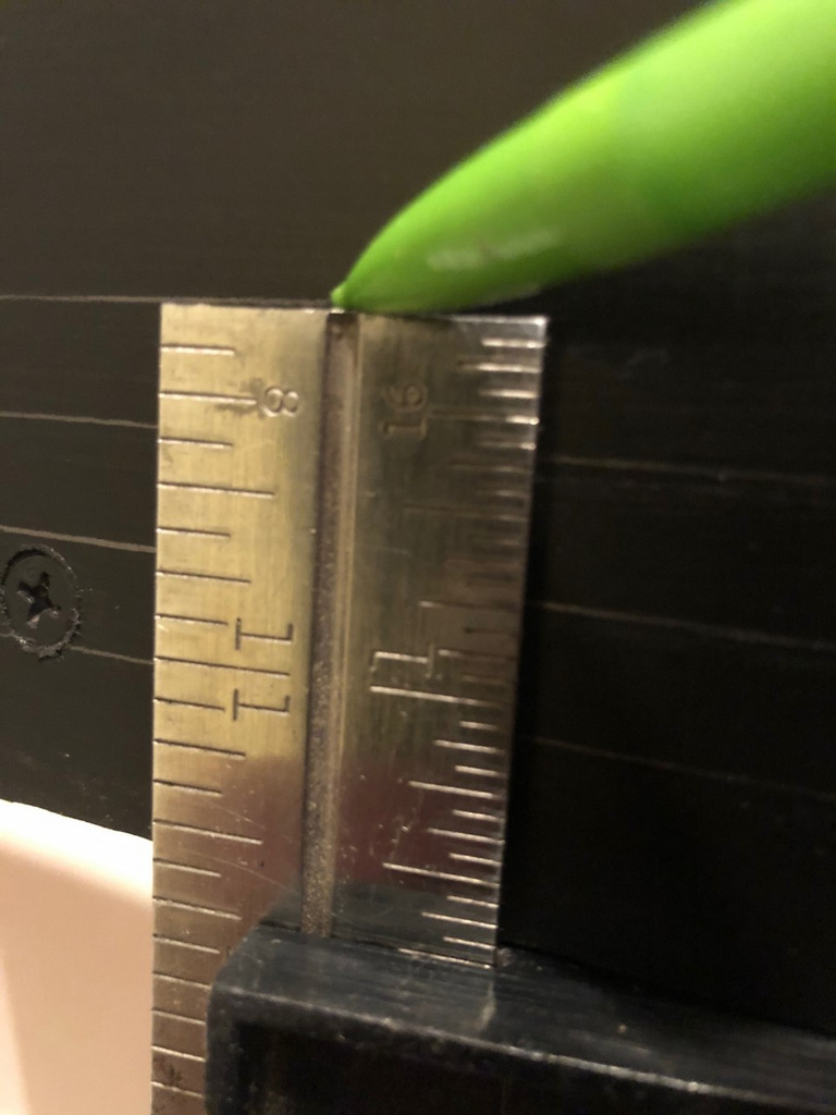
On my last layout, I drew the track diagram onto the front of the fascia, and it worked so well I decided to continue it on my new layout. It’s essentially an elongated track diagram like you’d find in a railroad track chart that lines up with the adjacent track and switches on the layout. I draw the lines parallel to the bottom of the fascia 3/8″ apart. To draw them, I’ll set a combination square so the end of the ruler is at the exact height I want when the square is pressed against the bottom of the fascia, then I’ll run the combination square around the bottom of the fascia while dragging a pencil along the top to draw it onto the fascia. I draw the switches onto the fascia at 45 degree angles with the convergence drawn where I want the switch control rod to be placed (directly perpendicular to the switch mechanism usually). One lesson learned from my last layout I was able to incorporate into this one is that the “straight” line through a switch control is the “normal” position of the switch while the “divergent” line represents the “thrown” position. It required a little “wiggling” of the track lines in the yard ladder to make this work, but it’s intended to help operators understand how to set the switches before departing a town.
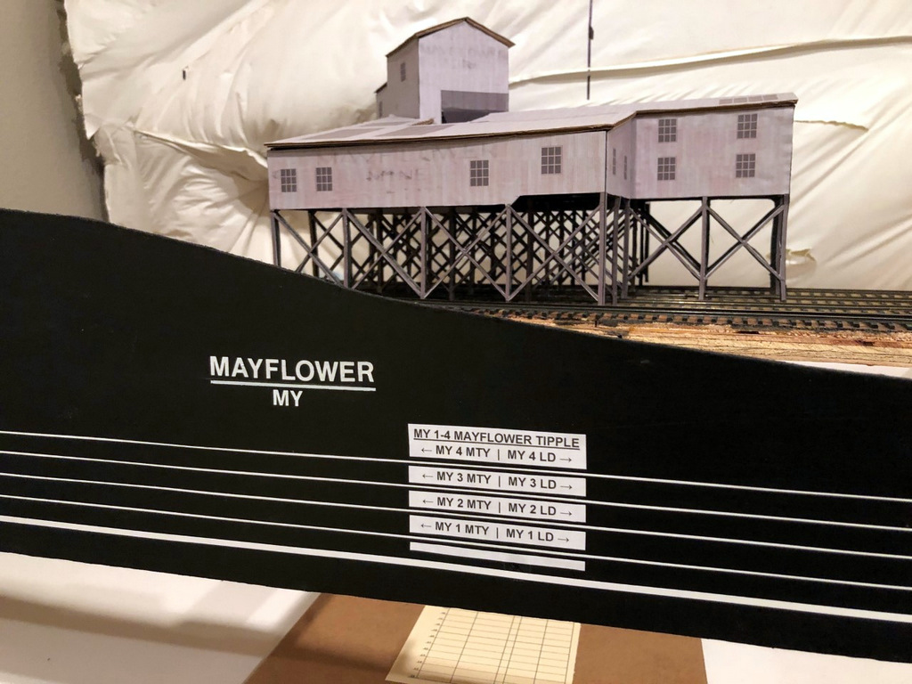
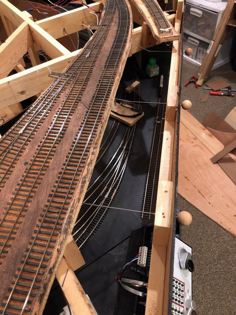
I installed the switch control rods (see full article on switch control mechanisms here) after the lines were drawn but before placing the graphic tape on the fascia to represent the tracks. I use two sizes of white graphic tape for the tracks, 3/32″ to represent the main, and 1/32″ to represent sidings. This offers another visual clue for operators so they know which tracks not to block and what to leave clear after leaving town. Next come the labels. Every town on the layout has both a name and a unique 2-letter destination code for routing cars. In this case, Mayflower is represented by “MY.” Within each town, each track has a unique number, for example, MY 1 is the tipple track for the Mayflower Tipple closest to the main. For tipples, I also designate where the empty (MTY) and loaded (LD) cars go, so an empty hopper destined to be loaded on Mayflower’s outermost track would need to be placed at MY 4 MTY. Towns are labeled with large dry transfer lettering with the town name above a line and its destination code in smaller letters below. I also cut a small gap in each track tape on the fascia near the switch and use dry transfer numbers to label each track by number. Industries are given white labels with black lettering that gives the industry name, town initials, track number(s) and MTY | LD track dividing line if needed (see picture of the Mayflower Tipple and its labels). If two or more industries are on the same track, I use a “B,” “C” or so forth to denote each spotting location. In the case of Mayflower, I’ve identified a spot on load track 4 where I might have operators occasionally spot cars of supplies and a spot on the tail track of the main where I might have them spot covered hoppers of AN–each of these spots has its own industry label adjacent to the correct track on the fascia track diagram to make it clear where to spot the cars.
There’s nothing really novel here, but I do think this method of using track diagrams on the fascia and integrating switch controls, town names and industry track designators with unique operational codes goes a long way toward making the layout more intuitive and operator-friendly.