Category Archives: Wiring

Installing Automatic Grade Crossing Signals

CV Local and grade crossing signals
The CV Local led by L&N RS3 100 crosses Bonny Blue Road with its newly installed crossing flashers

Many of the grade crossings on the St Charles Branch didn’t have flashing signals and were protected by flagmen or fusees (see how I simulate fusees here), but a few of the more prominent crossings were protected by automatic flashing signals and bells. One of those crossings is Bonny Blue Road which crossed two legs of the wye in St Charles. I was looking for a way to make these signals work automatically with nothing required of the crews (beyond sounding the horn for the crossing) and no hardware needed on any rolling stock. I quickly settled on using IR sensors mounted near the tracks to trigger the circuits required for the crossing. While many of the major manufacturers of railroad electronics offer circuits for flashers and for triggering based on sensors, there seemed to be a lack of good, simple options for the sensors. So I did what many of us do when we’re looking for something–I turned to eBay.

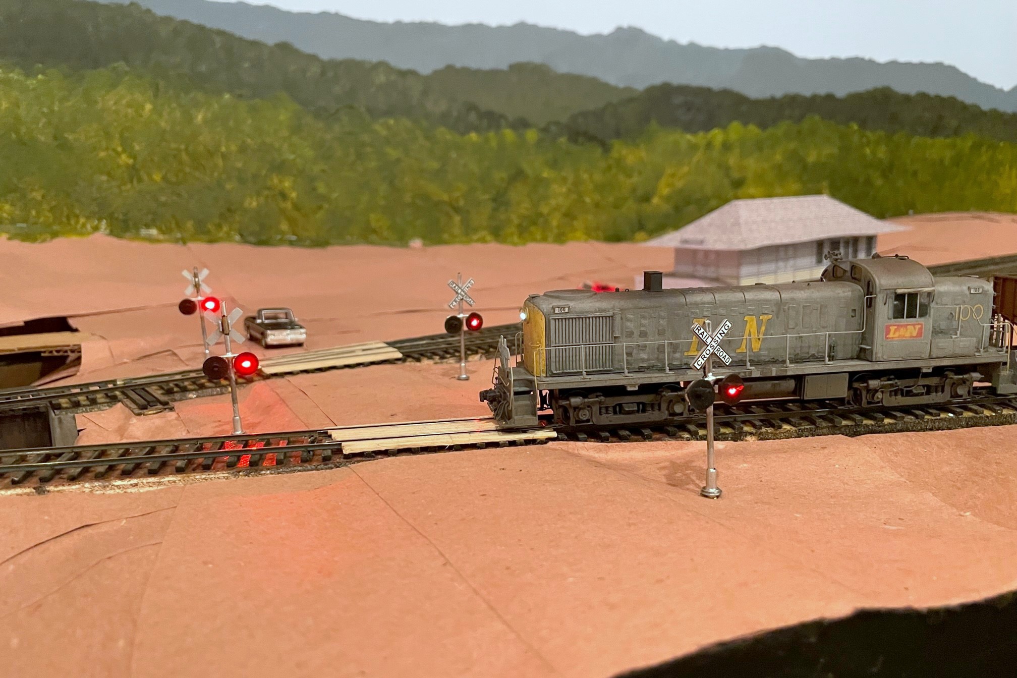
I found a lot of products for flashing crossing signals, but one it particular caught my eye. A company called “WeHonest” was offering what looked to be decent looking LED signals that came with a flashing circuit for a very reasonable price. Being a little suspect of a foreign company calling itself “WeHonest,” I needed four signals, so I ordered a couple sets and hoped for the best. I ordered the signals with two heads instead of four (front and back) because my signals would only been seen from one direction, and the ones with four heads looked too thick front-to-back (I plan to add dummy heads on the back later). When they arrived a couple weeks later, I was impressed with the quality for the price. The lettering is easily readable, the construction is mostly metal, and the size and shape are good for HO scale. I had to clean up some areas of the metal crossbucks, and some of the silver paint flaked off, but these were easy fixes. I initially hooked up the flashing circuit to a pushbutton on the fascia, and the flashing circuit worked flawlessly and controlled all four signals in a synchronized manner.

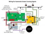
The signal piece was solved, so now I needed a way to automatically control them. My confidence in “WeHonest” was bolstered, so I explored their options. They offer a “model train detector automatic signal controller crossing system trigger etc” (also called a “master board”) which shows a diagram of how it can be configured to trigger a grade crossing flashing circuit using simple, single-unit IR sensors that don’t require a broken path. I also needed a circuit that could support four sensors due to the tracks that would trigger this grade crossing, and while the board only supports two sensors, their diagrams show that you can connect more sensors via separately available splitter cables. They also offer a sound effect circuit with multiple grade crossing signal bells (and a rooster). I ordered a master board, sound effect board, two splitters, and some additional IR sensors.

Wiring Diagram for Grade Crossing Signal Circuits
Wiring diagram showing the connections needed between the three circuit boards, signals, and sensors

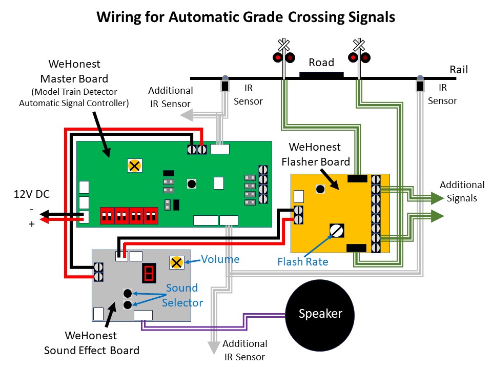
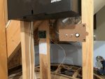
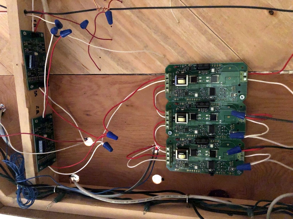
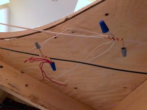
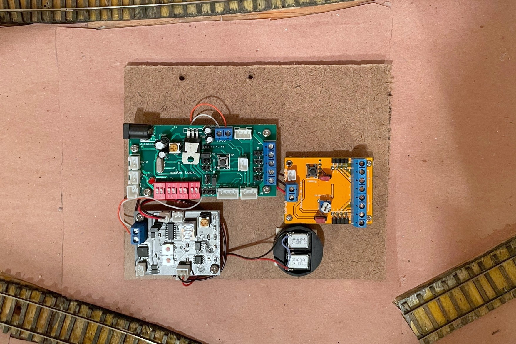
The documentation you see on eBay is all you get, so it took some studying and tinkering to set things up, but it wasn’t difficult. The basic idea is the master board is connected to 12V DC and the IR sensors. The sound effect board and flasher circuit are daisy chained off the 12V DC “output” side of the master board which is only live when the IR sensors are triggered. The only surprise on wiring was there are no normal contact screws for the 12V DC input, only a plug for an adapter and a specific connector type (both of which are sold separately). I found a plug off an old RC helicopter I disassembled years ago that did the trick. I mounted all three circuits and the speaker on a piece of masonite to keep the wiring tight and organized. Rather than use the supplied speaker, I attached a pair of baffled cube speakers I had pulled out of a locomotive when I replaced it with a Scale Sound System speaker.

Grade crossing circuit boards
I mounted all three circuits and the speaker on a single piece of masonite to declutter and protect the wires

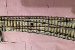
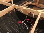
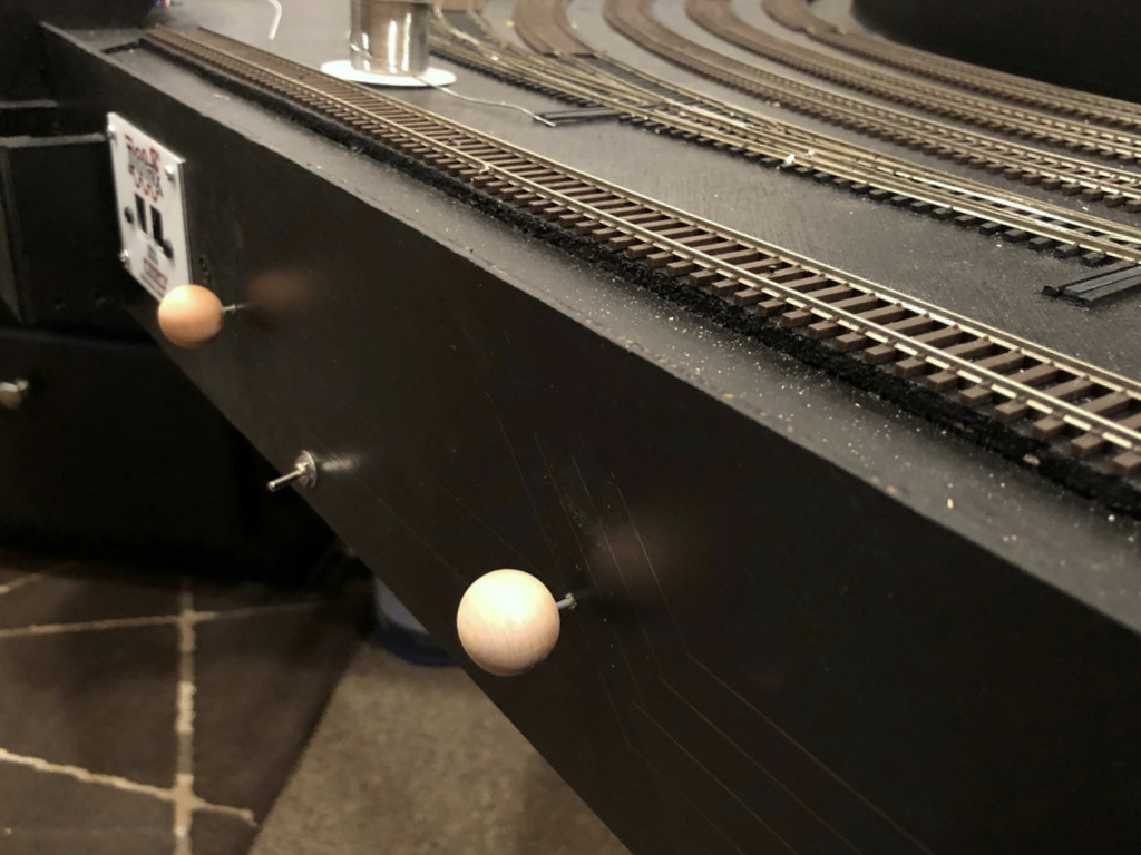
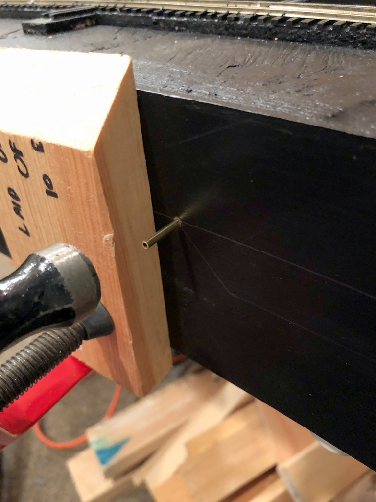
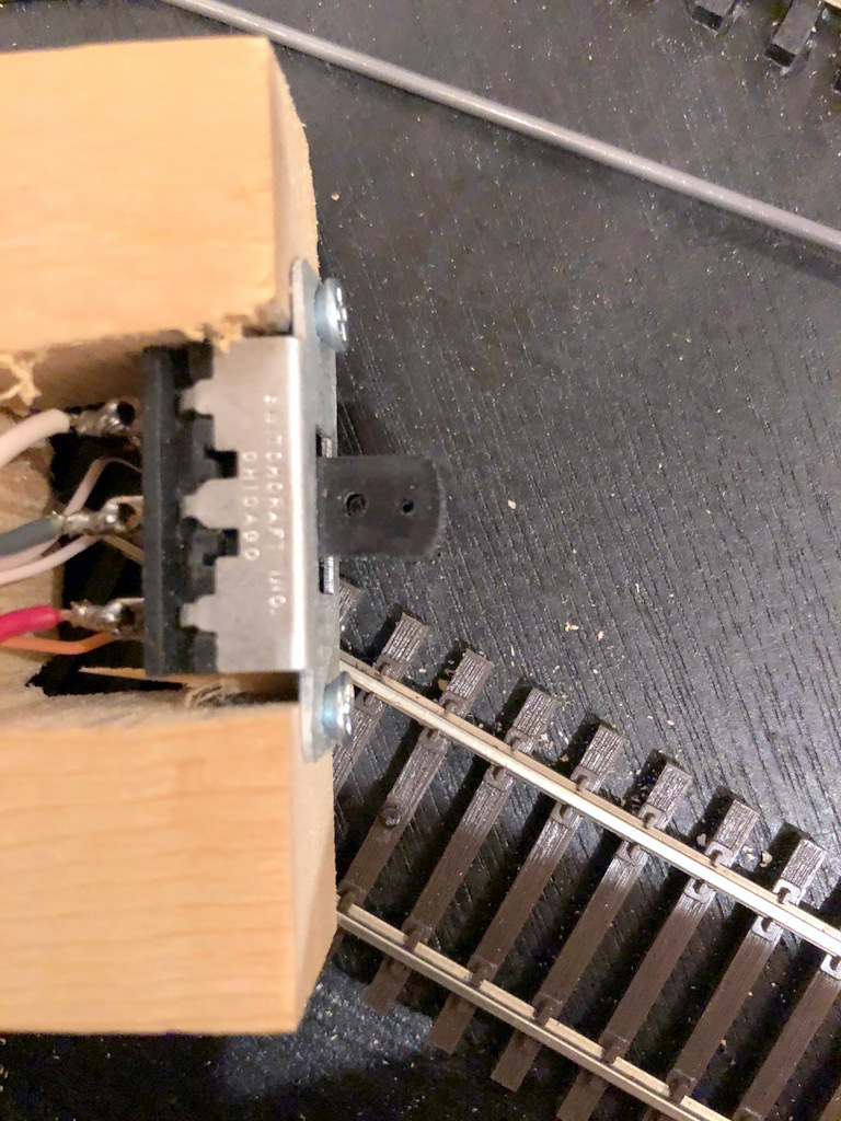
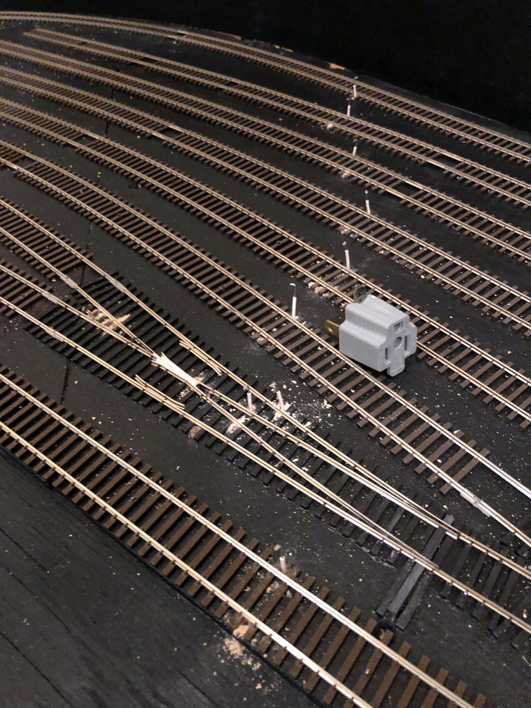
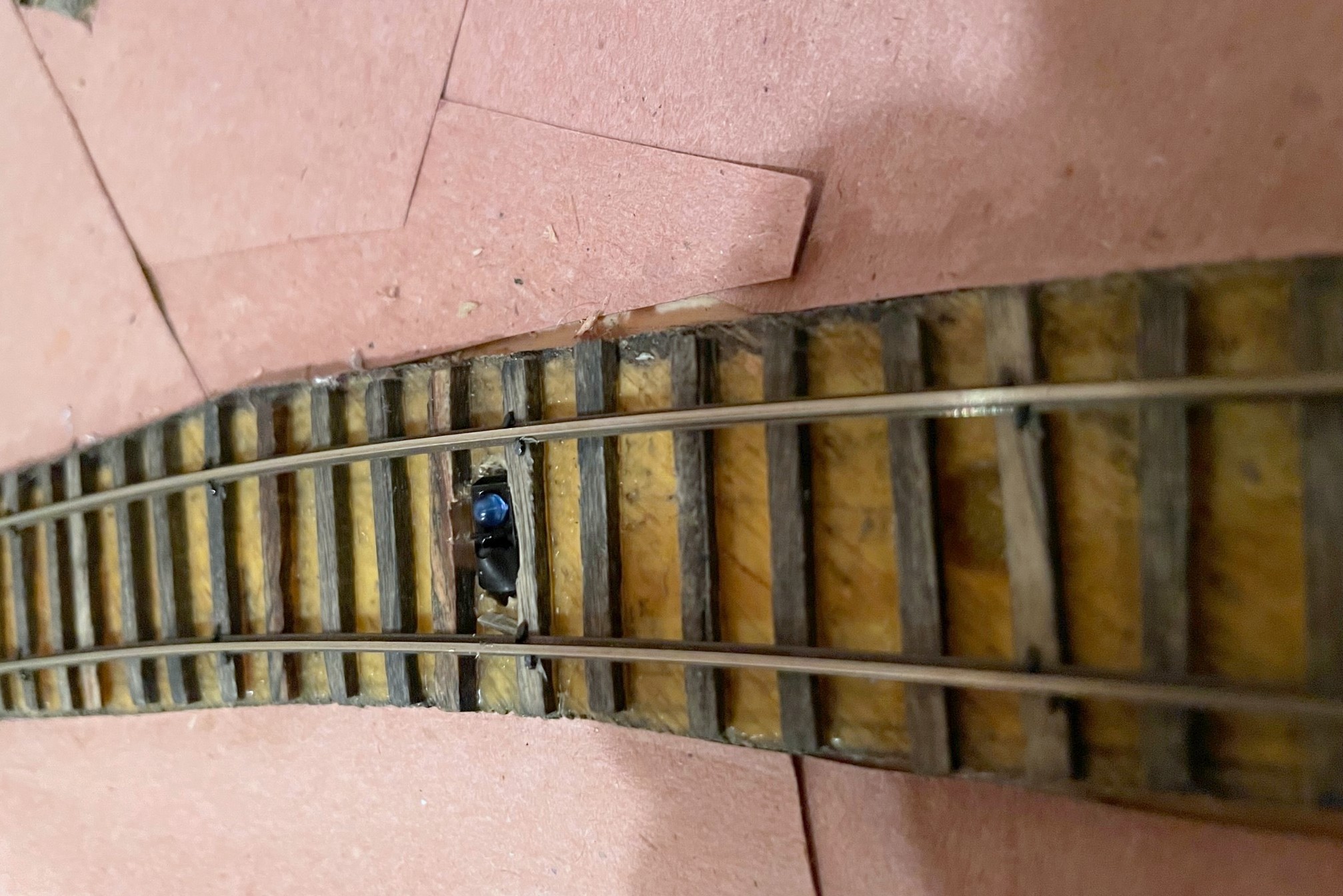
I installed the IR sensors between the rails and ties as the company indicates in the pictures. When anything passes over it within a couple inches, the IR sensor is triggered. There is no documentation on how the sensor works, but it has two elements, a blue dome and a black dome. I can only speculate that it transmits IR from one dome and receives reflected IR in the other dome. When I hooked everything up, it worked great… with two IR sensors plugged into the two separate sensor inputs on the master board. When I tried to use all four IR sensors, it would trigger the circuit no matter what I did even if nothing was present. I noticed some sensors were more sensitive than others, so I experimented with different placements and combos and even the positioning of the elements within the sensor. Unfortunately, I destroyed one of my sensors in the process, but thankfully they’re inexpensive, and I found the WeHonest customer service to be very responsive and helpful!

Grade crossing IR sensor
Here’s an IR sensor with a portion of the black dome covered in electrical tape to decrease its sensitivity

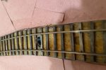
When my replacement sensors arrived, they did the exact same thing as before. Two sensors worked fine, four sensors triggered the circuit even with nothing present. I really liked the overall operation of these circuits, so I kept experimenting to see what might work. I speculated that the circuit detects based on a threshold of received IR energy–with one sensor, the ambient IR was low enough to stay below the threshold, but with two sensors, the ambient IR increased above the threshold to make it appear a train was present. I found that if I covered a portion of the black domed element on some of the IR sensors, it would keep the circuit from triggering but would still trigger if a train passed. After playing around, I found covering about 60% of the black element of all IR sensors with a small piece of electrical tape made everything work as intended.

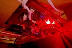
Now that I’ve worked out the kinks, I’m very happy with the crossing! I’m able to control the sensor sensitivity via the electrical tape, I can control the flash rate of the LEDs via a dial on the flasher circuit, I can select the bell sound from one of several good options on the sound effect circuit, and all of this works automatically with no actions needed from the crew. I have two more flashing grade crossings to go on the upper level, and I’m satisfied enough that I’ve already ordered the parts to replicate this installation on those crossings.

Farewell to the Mighty Z

DCS50 Zephyr
This Digitrax DCS50 Zephyr has served me faithfully for more than a decade on two layouts

***Update Oct 22, 2022. The Zephyr is not yet gone, and I may just keep it. I’ve figured out that I can still use it to turn track power on and off, even in booster mode, and the odd scrolling LEDs that come with placing the unit in booster mode aren’t quite as annoying as I remember. It also seems kinda handy to be able to quickly punch in a loco address and run a locomotive with the Z when doing things like speed matching… so, even though it’s no longer my command station, it may just stay right there on the fascia.***

This past Wednesday marked a milestone on the layout–it was the last time my layout was controlled by my venerable and dependable Digitrax DCS50 Zephyr! The “Z” is known as an entry level system, but it’s historically been my favorite to use as a command station because it’s very easy to operate and made a great stationary controller for creating consists and programming decoders. On both my previous layout and this one, I used a specially made box created just to mount the Z on the fascia in a convenient spot. The Zephyr’s 2.5A were never enough to power my entire layout, so there’s been an old DCS100 command station/booster serving as the booster behind the scenes, but the Z has always been the command station, and I’ve always had fewer than 10 locomotives on the layout at once, so the “slot” limitation has never been an issue.

Two things have happened recently that precipitated a change away from the Zephyr. First, thanks to my adoption of sound decoders and their braking features in all locomotives, I switched from “universal consisting” (command-station consisting) to “advanced consisting” (decoder consisting) to be able to control functions in all decoders simultaneously, so I can do all my consisting in JMRI instead of in the command station. While this method takes up even fewer slots in a command station, it also eliminated the need to create consists using the Z, one of its greatest strengths. Secondly, my old DCS100 has been getting more and more finicky over the years, often being disagreeable and “forgetting” its a booster. This never created any operational problems, but it was a constant source of angry beeps from the DCS100. I had a few options. First, I could just revert to using the DCS100 and upgrading to a newer advanced throttle (it came with an ancient DT100), but the DCS100 was starting to show its age. I also played around with a new generation Zephyr Express (DCS52), but I found the screen and buttons too bright (I want to run night operations), and the DCS100 REALLY didn’t appreciate working with the new Z, and it was more difficult than I’d hoped to get them to play nice together. Ultimately, I decided that the best answer would be to just upgrade the whole command station/booster combo.

DCS210 on the layout
The new DCS210+ in its spot on the staging level

I ended up going with the Digitrax Evolution Express (EVOX) which includes a 5A DCS210+ booster, 100-slot command station, a USB interface, and an a DT602 advanced throttle to control everything. It’s plenty of power for the layout, and I’ll never need the additional capacity of the top end command station. I splurged on the duplex radio version because I figured it would be worth it to upgrade my 2-way radio system to the newest receiver (UR93), and I wanted to preserve the ability to use the DT602 wirelessly, even if right now it’s serving as a glorified power button. Installation of the new system was easy, and everything works like a champ! I’ve also now got a spare command station, spare 5A power supply, and spare duplex radio receiver if I need them. I’ve also got a backup method for connecting my Digitrax to JMRI, even though for now I’m sticking with my old PR3 rather than using the DCS210+ USB port… it’s working well, don’t mess with it!

Anyway, I didn’t want to let this moment pass without giving a big shout-out and thanks to my Zephyr for the many years of faithful service on the layout. I don’t know many who use a Z as the command station for a good-sized, serious layout, so I was happy to be a long-time advocate! I already miss one simple thing: the ability to just push a button on the Z to turn the track power on and off. I’ll say farewell, though I have no plans to actually get rid of my Z any time soon… maybe I need a stand-alone programming station… hmm…

One final thing. If you’re trying to turn the track power on or off using a DT602 super throttle, and you can’t get the soft keys for track power to stay there long enough for you to actually push them, you need to press on the LEFT side of the power button and not in the middle. Might just save you a help-desk ticket with Digitrax… not that this happened to me.

Loconet Functional Diagram - St Charles Branch Aug 2022
Here’s the updated functional diagram of the Digitrax system on the layout


Fast Clocks on the St Charles Branch

Fast Clock in the Layout Room

Today I upped the operations realism a couple notches on the St Charles Branch by adding fast clocks!… Ok, with only half the tracks built and with only one partial operating session under my belt, it doesn’t take much to up operations several notches at this point, but the fast clocks are still really cool! While fast clocks are an important part of operating layouts, I was surprised at just how few good options are out there, especially for analog fast clocks. There are digital options available that work with your DCC system (nice feature), but modeling the ’60s and ’70s, I felt a digital clock display would be too gross an anachronism, and I’m working hard to transport operators back in time when they’re on the layout. I even played around with creating my own “analog” fast clock using MS PowerPoint which actually turned out pretty good for what it is–it works, but it was never intended to be a permanent solution. Feel free to download the “Poor Man’s Model Railroad Analog Fast Clock” (below) and play around with it–it will function somewhat online, but it works much better if you download it. You can read more about it and download a digital version as well here.

Fast clock in the crew lounge
Regulator-style fast clock in the crew lounge. The FCC4 system let me retrofit this hand-made clock.

For the real solution, I needed a way to have multiple physical analog clocks all synchronized with an adjustable fast-clock ratio. I narrowed it down to two systems. The first was a WiFi system that offered both digital and analog clocks, but it was limited to a single style of analog clock, and I don’t really need MORE radio frequency waves in my house. In the end, I opted for Mike Dodd’s FCC4 fast-clock system. The FCC4 consists of a control board, three simple switches (run/stop, advance, and reset), and as many clocks as you need running off a two-wire bus. What intrigued me most was how Mike implemented the analog clocks–YOU buy the clocks, and he supplies the replacement mechanisms that will fit in just about any wall clock you can buy today. That feature enabled me to buy a clock for the layout room that had the style I wanted, AND it allowed me to convert a “Regulator” style clock made by my wife’s grandfather into a fast clock for the crew room (i.e., the rec room adjacent to the layout).

Temp fast-clock control panel
My temporary fast-clock control panel (the FCC4 is mounted in the background)

You can save some money by buying the kit version and assembling it yourself, but I decided to buy the assembled and tested versions of the controller and clock mechanisms, and everything worked like a charm (so refreshing in this day and age). I just needed to swap out the two clock mechanisms (a fun 30-minute project), add a few switches, and run several wires. Installation of the wires through the walls was the most difficult part of the project, but even that was pretty straightforward. In the end, I now have two fast clocks set to a 4:1 ratio that I can turn on and off, advance at a 17:1 ratio if needed, and reset to my session’s start time (5:30 AM for now) easily, and if I ever expand the layout into the spare bedroom next door, I just need to run a couple more wires and buy another mechanism to have another clock. I mounted the control board on a stud inside my helix space where it will be hidden from sight but easily accessible via a short crawl for troubleshooting or adjusting the ratio. The controls are on a temporary board for now–I’ll eventually install them in a recessed portion of the upper-level fascia to keep the switches away from little hands and wayward elbows.

If you need an analog fast-clock system, I would definitely check out the FCC4! Not only is Mike Dodd very responsive to questions, but he’s also a model railroader himself, so he’s designed this system from the perspective of an operations-oriented layout owner. I’m looking forward to my first operating session using the clocks where the times on train orders are more than just numbers on a  piece of paper!


Lower Level Fascia Complete

Lower Level Fascia
Lower level fascia complete and awaiting a few labels
Looooong switch push rods
Push rods can indeed be used for distant switches (48″ here) if properly guided and reinforced

This week’s project was completing the fascia for the lower level. I love the look of the curved black fascia and track diagrams. I’ve detailed fascia elsewhere, so I’ll stick to what’s unique here. While the switch mechanisms can be partially installed prior to fascia, it takes the facia being in-place to install the manual switch control knobs and push rods. While most of the mechanisms were pretty basic, there are three switches more than 30″ from the fascia on the “RR east” end of St Charles wye where the tracks emerge from the helix and staging. I wasn’t sure if I’d be able to use the push rods for long distances, especially since two of the switches are beyond 36″, the length of the .062″ steel rods I use. The trick with the push rods is the longer they are, the more they tend to flex and bend (and, in turn, not throw your switch mechanisms). This can be partially rectified by using additional brass tube guides in wooden blocks along the rod’s path, about every 12-15″ or so. That was good enough for the first mechanism that was <36″ from the fascia.

St Charles Fascia
St Charles wye has two insulated tracks where engines might tie up

For the longer rods, I decided to try connecting 2 steel rods using a 6″ piece of 3/32″ brass tubing and Gorilla Glue. I use the Gorilla Glue to attach the wooden knobs to the steel rods, so I know it’s got at least SOME game with metal. Since these rods will be hidden by scenery, I decided not to trust glue alone, so I lightly bent both the tube and steel wire about 1″ from the end of the tube on both sides–if there’s one thing I’ve learned, even a slightly bent .062″ wire does NOT want to pull through a 3/32″ piece of brass tube! Once I added the bends, the mechanism is solid as a rock! I’ve now verified that the manual push-rod controls are viable to at least 48″ from the fascia–not bad at all, and all remaining switch controls should be well under this length.

Another unique feature of the St Charles fascia is the addition of two SPST toggle switches that isolate two of the tracks from the wiring bus. A while ago, I detailed how I did something similar for my staging tracks so I could easily silence sound locomotives when they’re not actively involved in the operations. St Charles was often home to a mine run, so the pair of mine-run engines hung out on either the “house track” or aptly named “engine track” adjacent to the depot. Since these are the only tracks on the levels with scenery where I anticipate parking locomotives, I decided to give them the same insulation and toggle setup as the staging tracks. While I will likely rarely use these, I figured it’s SO much simpler to add them now than decide I need them after-the-fact.


Major Milestone – Lower Level Track Complete

L&N taking a test spin
L&N RS3 100 takes a trip around the wye at St Charles
St Charles yard tracks complete
Completed St Charles yard tracks

Hit a major milestone yesterday: the lower level tracks are complete! I completed the first scene, the end of the line at the Mayflower tipple, several months ago, and the last few months I’ve been working on the long scene at St Charles. St Charles – the branch’s namesake – was home to a wye, a depot, a couple small tipples, and a three-track “yard.” St Charles was also home to a mine run when the tipples were busy, so this is the central scene on the layout. All told, the St Charles scene is about 26 linear feet long and required 14 hand-laid switches (about 1/2 of them curved) and a couple of bridges.

Electrically, I made the entire Mayflower branch an auto-reversing zone for the wye. Can I just say the On-Guard AR solid-state DCC auto-reversers are awesome? The switching of polarity on the wye is absolutely seamless and unnoticeable–I highly recommend them! I also isolated a single rail of both the “house track” and “engine track” in the middle of the wye and will place a switch on the fascia. This will allow me to turn the power off to the two tracks that would hold idling power in case any sound locomotives get annoying. Next step is fascia and switch controls.

DCC Zones – Planning for Future Operations

This post is less of an update and more of an effort to chronicle a minor but important part of layout construction: DCC track bus planning. Installing DCC has two major components, the first is wiring up the DCC system with its command station, booster(s), throttle panels, computer connections, wireless throttle receiver, and network cables–I covered the installation of the DCC and logical connections of the DCC system here. The second component of DCC is installing the wiring for the track which includes electrical buses, circuit breakers, and dividing the layout into zones which I’ll cover here. Even if you don’t plan to use circuit breakers, its still a great idea to “future proof” your layout by wiring for zones–you can always tie the zones together at the booster, but you don’t want to be installing new buses and feeders under finished scenery. These zones will also help with electrical troubleshooting if you can’t find a short–you’ll at least be able to isolate it to a smaller section of track.

DCC indicator light on UP5
This UP5 panel’s Loconet light is connected directly to the booster (note the “M” label for “master”)

My layout is small enough to easily be powered by a single 5A DCC booster, in my case, an old Digitrax DCS100 Chief acting as a booster (a DCS51 Zephyr is the command station). At most, I’ll have 3 trains and perhaps 6 locomotives running at any given time. The DSC100 can handle this current easily, but with circuit protection provided by only the booster, if any one locomotive runs against a switch and shorts on the frog, power for the entire layout and all trains shuts off. The solution? Dividing the layout into zones and using solid-state circuit breakers!

I already needed at least three zones on the layout because I have two reversing loops which need to be isolated from the main bus and powered through an auto-reversing circuit breaker. In my case, I use the On-Guard AR reversing breakers from DCC Specialties. Although a tad on the expensive side, the solid-state AR circuits are rock solid and work more reliably than their analog counterparts, especially with the current draw of sound locomotives. Aside from the reversing zones, I decided to divide the remainder of the layout into 3 additional zones, one per level. How many zones you use is a balance of cost and functionality–too many, and the cost quickly gets out of hand along with the wiring (each zone needs its own wiring bus), too few, and operators causing short circuits will quickly ruin the fun of other operators in the same zone.

With my max of three trains in mind, I drew zone lines primarily to ensure each train would be in its own zone most of the time. Consequently, the zones are different sizes based not only the amount of track it powers but the operating locations for the trains. For example, zone 3 is the largest on the layout and powers not only the entire upper deck but the helix between the lower and upper decks as well. That’s a lot of track, but only one train at a time will venture to the upper deck, so it can be large. The main level is two zones with one covering the wye and yard at St. Charles, and the second (a reversing zone) covering the branch to Mayflower–there will often be a train at St Charles while another works the Mayflower Branch. Finally, I made the staging level its own zone (along with a second reversing zone) so that operators moving things in and out of staging won’t impact operators on the visible portion of the layout.

Once I knew where the zones would be, I ran an electrical bus from the vicinity of the booster all along the benchwork where the tracks of that zone would go. I’m all about overkill here, so I use household Romex 14 gauge copper wiring that I pull out of the sheath. I drill holes and run the black and white wires through the benchwork about 4″ apart. One important step is to LABEL THE BENCHWORK with a Sharpie every few pieces of wood, especially if you have multiple buses running side-by-side, so you don’t become confused as to which track you’re hooking up to what zone–if you mess this up, your track could be wired to multiple zones simultaneously and eliminate any benefit of electrically isolating the zones. At the ends of the run, I just wrap the lines around a drywall screw. If I need to run a bus in two directions, I just make a junction and join the three wires together with a wire nut, just like I would do with household wiring.

Pigtails for the DCC bus
Pigtails on the DCC bus, note the zone IDs (2 and 2R) marked on the benchwork

I strip about 1″ of insulation off each wire about every 2-3′ where it will connect to track, and I wrap a 4″ section of the uninsulated ground wire from the Romex around the bare spot about 3 times leaving 1″ or so hanging off both ends. A little solder keeps this pigtail in place. I’ll offset the white- and black-line pigtails by about 4-6″ horizontally in addition to the distance between the wires to minimize the risk of shorts. These pigtails become the connection points for track feeders using wire nuts. Of course, you’ll need to physically separate the tracks between zones by either cutting gaps in the rails or using a plastic insulating joiner. Be sure to overlap your gaps by 3/4″ – 1″ for zones connected to an auto-reverser!

Between the bus for each zone and the booster is a circuit breaker, in my case a PSX-3 (essentially 3 PSX-1s) from DCC Specialties (I covered how to program these with a DCS51 here). Like the auto-reversing breakers, the PSX breakers are solid-state and are well worth the money over analog breakers, especially if you’re running sound locomotives. I have been extremely impressed with these units so far! The PSX design makes it easy to daisy-chain multiple breakers with just one set of wires to the booster. The only split I had to make was after the PSXs when I had to run the last booster connection off the PSX to the two AR circuits. To make the connection to the buses easier, I made a simple “panel” on part of the benchwork where the 14 gauge wires for each bus come through, get wrapped around a drywall screw, and have the ends exposed for connection to the PSX via smaller wires connected with wire nuts.

DCC zone indicator lights on UP5
Zone 1 and 2 indicators using UP5 Loconet lights

A final step for me was figuring out a way to monitor each zone to know what’s active and what’s shorting out. It’s more difficult to detect a short with the PSX than the DCS100 because the booster makes a distinct noise when it’s reacting to a short, but the PSX is silent. For monitoring, I turned to the Digitrax UP5 universal interconnector panel. I have five of these panels at various spots along the fascia of the staging level for connecting throttles, and each has a “track status” light that can be wired to the track bus. I chose one in proximity to each zone to be the “zone indicator”, labeled with a sticker for the zone number to help me remember, and wired it to pigtails of the corresponding track zone. This way, if a short occurs, only one light corresponding to the affected zone will go out to aid troubleshooting. I wired the UP5 adjacent to the command station and booster directly to the booster wires (no circuit breaker in between) and labeled it to be the master monitor–if it’s on and everything else is out, it tells me the problem is somewhere in the circuit breaker wiring.

Finally, I drew pictures (the ones seen here) of the zones on top of a layout diagram to help me remember exactly where the zones go, and I placed this in my layout binder with all the other helpful information on the layout. This wiring took a good bit of time to plan out and install, but now the layout has the robust electrical backbone to make for smooth connections, easier troubleshooting, and ultimately more fun for operators.


All the Boring Stuff – Wiring, Wiring, Wiring

I haven’t added an update for a while because the layout doesn’t really look any different. That’s not to say I haven’t been working, it’s just been all the boring stuff – wiring. It may be boring, but if you want your layout to run well, it’s doggone important, so it shouldn’t be left as an afterthought.

Power switches for staging tracksFirst, I corrected an issue I first noticed when running trains around the staging level – sound! I never ran sound locomotives on my previous layout, and now that I’ve got a few, I noticed how annoying it is to have diesels sitting in staging making idling noises that are easily heard throughout the room. These trains are supposed to be dozens of miles away, and I don’t want to hear them while they’re in staging. Of course, there’s the option to “mute” a sound locomotive temporarily, but I don’t want to force operators to go through an entire consist muting and unmuting every time they pick up or drop off a train in staging (and every time a short occurred, all the sound would come right back on anyway). For a solution, I went “back to the future.”

I installed a small SPST toggle switch (picked up 20 for cheap on eBay) for each staging or locomotive track (9 total) on the fascia where the track diagram will be. Unfortunately, this meant pulling dozens of feeders from the staging tracks and running a secondary bus for one rail under each track that’s connected to the switch. Thankfully this didn’t involve any de-soldering because all my feeders are connected via wire nuts. Now I can turn off the power to any staging track with sound locomotives until they’re needed, and all the operator has to do is flip a single switch. Old school “electrical block” solution to a DCC problem.

PSX3 InstallationWhile I was at it, I broke down and ordered a DCC Specialties PSX-4 solid-state circuit breaker to go with my On-Guard-AR auto-reversing circuit breakers. I’ve been planning to do this all along and wiring for multiple zones, but after reading through the PSX documentation, I discovered my understanding of the PSX-4 and how it interacts with AR breakers was a little lacking. I didn’t know that the AR breakers should not be wired off a PSX zone but directly wired to the booster themselves. Turns out with the two reversing zones already protected by an AR circuit breaker, I really only needed a PSX-3 because I only have one non-reversing zone per level (1=staging, 2=lower level, 3=upper level, 1R=staging reverse tracks, 2R=St Charles wye to Mayflower). “Snap” – “hey look, now I have a PSX-3 and a spare PSX-1”. . . smart DCC Specialties! Not gonna lie, it was a little confusing to program the PSX to work well with the AR breakers using the Digitrax Zephyr, but I finally figured it out:

  • Set the Digitrax booster to .5 sec short circuit trip using booster instructions (CV 18 to “c” on my DCS100)
  • Solder the Digitrax jumper on each PSX zone per PSX instructions
  • Set the PSX to programming mode via the jumper per the PSX instructions
  • Ignore the part about setting the PSX address unless you need the PSX to respond to “on/off” or other special commands from the DCC (If you just need it to be a circuit breaker, you don’t)
  • Connect a single PSX zone directly to the Track A / Track B from the Zephyr
  • Turn the track power on on the Zephyr
  • Put the Zephyr into “OPS Programming” mode
  • Select CV55 (“CV”, “55”, “CV”)
  • Press “1” and “CV-W” (add delay to the PSX so the AR zones will trip/reverse first)
  • Select CV65 (“CV”, “65”, “CV”)
  • Press “80” and “CV-W” (set delay to 10ms which works for my setup)
  • If Zephyr shows “Busy,” exit programming mode and try CV65 steps again
  • Set PSX to ops mode via the jumper per the PSX instructions
  • Repeat steps for additional PSX zones

Lower Level Wiring BusI encourage you to read all the instructions first and choose your own adventure–just sharing what worked for me.

Finally, before I lay subroadbed and track for the lower level, I had to add the wiring bus, or in this case, two wiring buses. Two are needed because the St. Charles wye needs a reversing circuit, and the reversing district carries over all the way to Mayflower. Lots of drilling holes, cutting open Romex, and pulling heavy gauge wire through. I still have to make the little pigtails for feeders, but it’s mostly done. Shouldn’t be long before I’m laying track on the main level!

Switch Control Mechanisms

I’m taking a pause on construction to work all the bugs out of the staging level before building on top of it, so I thought I’d share my method of building manual switch control mechanisms that operate from the fascia. I developed these mechanisms for my last layout, and since they proved to work so reliably, I’m doing the same on my current layout. What I like about these mechanisms is they’re rock-solid, easy to use, and unlike alternatives such as Caboose Industries ground throws, they keep fingers away from the scenicked area of the layout. As an added bonus, using a DPDT slide switch as the “guts” not only gives it a “snap”, but it makes it easy to power frogs and LED indicators if you want them.

The Design

HO Scale Manual Switch Control Mechanism Diagram

The figure shows most of the relevant parts of the mechanism. It’s essentially a DPDT slide switch mounted to a piece of 2×3″ lumber for the mechanism, a piece of .062″ music wire and a 3/4″ round wood ball for the control arm, a piece of .025″ music wire for the throw, and pieces of 3/32″ and 1/16″ brass tubing where the music wire needs to go through wood.

Making the Parts

Switch throw bell crank
The top portion of the throw bell crank made from music wire

I create the throw first by drilling a snug hole for the piece of 1/16″ tubing about 5/8″ from the throw bar of the switch. I normally drill this dead center between the rails on the frog side of the throw, but if you have benchwork interfering below, you can put this anywhere along the throw bar on either side. I’ve found 5/8″ distance works well with the DPDT switches I use–anything shorter and it won’t throw far enough; anything longer, and the wire is not stiff enough for a reliable throw. I cut a piece of 1/16″ brass tubing just long enough to reach the bottom of the subroadbed while remaining just a fuzz above the ties on top and gently tap it in with a hammer. Next I drill a hole large enough for the .025″ music wire in the throw bar adjacent to the hole for the tubing. I cut a piece of .025″ music wire about 4-5″ long and bend one end to fit perfectly into the throw bar (clipping it to avoid dragging under the throw bar) and dropping into the tube. While holding down the top part of the wire, I reach underneath and bend the other end of the wire as tight as I can by hand opposite the direction of the throw and perpendicular to where the control arm will go–it doesn’t matter that the bell crank is in line with the throw; it matters that it’s perpendicular to the direction the control arm will need to move. Finally, I use a pair of needle-nosed pliers to bend the wire toward the ground about 3/16″ from where it exits the bottom of the tube. The bell crank is now complete, and you should be able to easily throw the switch by moving the bottom of the wire back and forth.

Switch mechanism
Switch mechanism ready for mounting sitting next to its control-arm wire

Next I build the mechanism. First I solder feeders onto the DPDT switch–I use red and white for the connections to the track bus and gray or blue in the center for the connection to the frog. Next I cut a piece of 2×3″ lumber about 2 1/2″ long (you can use any size, but smaller will be more delicate, and larger will be tougher to fit around benchwork). Then I a notch about 1″ deep just wide enough for the DPDT switch to fit. At this point I designate a “top” of the mechanism and install the DPDT switch with small wood screws. With the mechanism placed between the throw and the frog, the feeders should be REVERSED from the normal orientation of your track bus. In other words, my track bus is normally oriented red/black-front, white-back, so I install my DPDT switch with the white feeder in front. Finally, I drill two holes through the slide portion of the DPDT switch, one just big enough for the .062″ control wire and the other closer to the tip of the switch for the .025″ throw wire. I’ve found drilling both holes with the smaller bit and then enlarging one prevents the plastic from breaking. I put a little countersink into the top of the holes by spinning an X-Acto knife in them to make it easier to insert the wires. NOTE: my switches are hollow inside which makes it a bit of a pain to insert the wires sometimes–it just takes a litte patience. I finish by drilling and countersinking two holes where I want the screws for mounting it to the layout will go.

The next step is the control arm. First I decide where I want the control knob on the fascia. For me, I use a simple track diagram on the fascia with switches drawn in (more on this in a later post), so I draw the diagram first, then drill the hole that will tightly fit the 3/32″ brass tube perpendicular to the ground and aimed toward the end of the throw crank under the layout. Then I cut the 3/32″ brass tubing to fit just through the fascia and 2×3″ board edging the layout. In some spots, there is no board, so I’ll glue a square piece of 2×3″ lumber behind the fascia to ensure adequate support. There might also be other lumber between the fascia and the switch. If its a fairly short distance (<12″), I’ll drill a 5/8″ hole where the control arm will go through. If it’s a longer distance, I’ll drill a second hole for 3/32″ tubing in line with the first–this isn’t tough to do if you take a piece of straight .062″ wire, push it through the fascia tube and mark where it hits the intervening lumber. The straigher you make these two tubes, the smoother the mechanism will be. Finally, I bend a control arm. Starting at the switch end, I bend the last 1″ 90 degrees toward the ground where it will go through the slide switch, then I make a slight bend downward about 1″ from the 90 degree bend toward the fascia hole, then another bend about 1 1/2″ from where it will go through the 3/32″ tubing. The sharpness of the anlged portion depends on how much room you have between the switch and fascia and how far down on the fascia your control knob will be. The shallower the bends, the more solid and reliable the mechanism will be. I cut it with a Dremel tool and cutoff disk (enjoy the fireworks!) so it will protrude about 1 1/2″ through the fascia and file the burrs off the end.

Mounting the Mechanism

Completed switch mechanism under the layout
Here’s what a completed installation looks like under the layout

This part is straightforward, but it can be tricky and sometimes frustrating to get the switch is exactly the right spot–it requires some experience and skill to get it right, and that experience and skill requires some misfires and mistakes to gain. I first install two 1 1/4″ drywall screws into the mechanism mounting holes with about 3/32″ of the tip sticking through–this gives a way for the mechanism to grab the subroadbed a little while you’re placing it. Then I insert the control arm through the DPDT switch and run the other end through the 3/32″ tube(s) and out the fascia. Next I place the mechanism onto the .025″ bell crank (this part can be tricky and frustrating if the wire and holes don’t line up well). Once everything is inserted, I place the DPDT slide in the middle position and do the same with the throw topside–with both of these in the middle position and the DPDT slide direction in line with the control arm, I press the mechanism into the subroadbed and hold it in place. While holding the mechanism in place under the layout, I’ll try work the mechanism to ensure it throws snugly to both sides. This is a matter of trial-and-error, but once I’m satisfied, I’ll put one of the screws into the subroadbed. Inevitably, it will leave a gap between the mechanism and subroadbed because I wasn’t able to pre-drill the hole. . . no worries. Then I’ll start the second screw, go back to the first and back it out then put it back in to cinch it up, then do the same to the second. If all has gone well, the control arm will easily push the slide switch to both limits, and the throw will push the point rails snugly to each stock rail. If not, back out the screws and try again!

Switch mechanism control knobs
How the completed switch mechanism looks on the fascia

Once I’m satisfied that the mechanism is where it needs to be, and everything is operating smoothly, the last step is to install the control knob. I first push the control arm wire in, then cut it off with the Dremel about 5/8″ from the fascia and file smooth. Then I drill a hole straight into and about 2/3 of the way through the round wood ball. After moistening the wire and ball, I add a drop of Gorilla Glue to the wire and place the wood ball onto the wire. It should be tight enough that you have to twist it on. I like for the control knob to sit about 3/16″ from the fascia when the knob is pushed in. Work the switch a few times while the glue is wet to make sure it feels right where you’ve placed it, then let it dry. Connect the feeder wires to the track bus and the third wire to the frog and the switch mechanism is complete! While it sounds like a lot of steps, if you mass produce the 2/3″ mounts and DPDT switches with pre-drilled holes and wires pre-soldered, you can install 3-5 mechanisms in an hour.

Layout Wiring

Layout wiring on the St. Charles Branch is simple yet very robust using common household wiring supplies. First, I’ve divided the layout into six blocks: four “main” blocks (1. Staging, 2. St. Charles, 3. Mayflower, 4. Upper Deck), and two reversing sections (1R. Staging loop, 2R. St. Charles Wye). Even though I don’t have a power block distribution circuit yet (like a PSX4), I’m wiring the layout for that eventuality and just tying all the blocks together at the command station as an interim.

Feeders and Bus Pigtail Connections
Feeders are connected to the wiring bus via wire nuts connected to pigtails along the bus.

The bus wiring for each block is copper Romex wiring. . . that’s right, Romex, the 14 AWG copper wire you use to wire household sockets and light fixtures. It’s overkill, but it’s easy to find, comes in long lengths, and the current loss for DCC applications is pretty much zero. I strip the outer sheathing, remove the bare ground wire, and use the black and white wires. I run them under the track through holes in the benchwork separated by about 2.5″. Lesson learned: if running the bus for two blocks side-by-side, make sure you label each about every other piece of wood to avoid cross-wiring blocks later.

I drop feeders at least every 5 feet, so on every 2-5 feet of bus wiring, I’ll strip off about 1″ of insulation and make a “pigtail” if you will using a length of 4″ of the bare copper wire (Romex ground wire) wrapped tighly around the bus core about 3 turns and soldered. I leave about 1″ of copper sticking off either end and cap it with a wire nut. I separate the pigtails for the white and black wires by about 4-6″ to avoid accidental contact of exposed wire.

Wiring Feeders
Wiring feeders from the rails to the bus under the layout. The gray plug marks the spot of connection to make it easy to cut wires to the right length.

Finally, the feeders. As mentioned, I try to drop them every 3-5 feet of rail. For bulletproof operation, every single rail on the layout is directly connected to the bus either through its own feeder or a single soldered joint to the rail next to it that’s connected to a feeder (no trusting rail joiners to carry current and signal). I drill the holes first, then drop pieces of 18 guage stranded wire through to connect to the bus. You’ll notice in the picture above the layout the little gray plug. I use this to mark the location of the pigtail under the layout so I can accurately cut the feeders to length, leaving about 1.5-2″ extra length to account for vertical distance through the subroadbed and some wiggle room for orienting the feeder to fit into the pigtail. Because I hand-lay my switches, I need a LOT of extra feeders for the point rails and frogs (connected to switches under the layout).

To make sure I hit all the holes, I leave the sawdust from drilling them in-place until all feeders are in. I also work one color at at time; white for one rail, red for the other. Once all the feeders of one color are in place, I’ll tin them with solder and solder each to the rail. Under the layout, I’ll gather together 2-3 feeders, twist them together, and tie them to the pigtail using a common wire nut (size depending on the number of wires being tied together). A little tug ensures they’re solidly in-place.

I’ve found this method creates rock-solid wiring that’s easy to modify and troubleshoot–just disconnect and reconnect the wire nuts as needed. This method also works perfectly with Digitrax DCC which prides itself on picking a slower data rate that works well with non-high-speed wiring. If using on a different system, I recommend doing some testing first.