Category Archives: DCC

Configuring DCC Consists for Directional Horns

As I’ve stated in previous posts, sound decoders have drastically changed my approach to DCC consisting. In an ideal world, I want all movement controls (forward, reverse, braking, dynamics) within a consist to be controlled by a single throttle, and I want only the lights, horns and bell of the lead unit to respond when an operator selects these functions. Digitrax’s “universal consisting,” unfortunately, doesn’t allow function-controlled movements like braking to go to the entire consist. Also, if you reverse the direction of the consist, you have to rebuild the consist to control both movement, lights and sound with the new lead unit. This is not a big deal for trains that only run in one direction, but every single one of my trains is an “out and back” where the lead unit of a consist switches, sometimes several times in a session. Asking operators to rebuild the consist every time they switch the train’s direction is not ideal.

Moving to “advanced consisting” (decoder-aided consisting) solved many of these problems but not all. Using the “consist” tab in JMRI, I was able to use the directional lighting features built into my Soundtraxx Tsunami 2 decoders to set the lights on the end units in a consist to “respond to consist address” but only in forward or reverse, thus solving the challenge of only getting the end lights in a consist to illuminate. The horns and bell, however, cannot be set to only operate directionally using the consist controls, so I was stuck with picking one loco in the consist to respond to all the horn and bell commands… this works, especially if all units use the same horn type, but it bothered me a bit to hear a Nathan M5 from the trailing GP35 instead of the Nathan P3 from the leading GP38. When I posed this question to a group of Digitrax experts, one of them pointed me to this video from Soundtraxx where someone had figured out how to use “alternate sound levels” function in the Tsunami 2 decoders to get directional horns, so I had to give it a try. The video left a few steps out, perhaps because they were using “simple consisting” (same address), so I had to experiment a bit to figure out how to make it work with advanced consisting, but in the end, I was able to get the consist to perform [almost] exactly as I had hoped using the following method.

The Gist

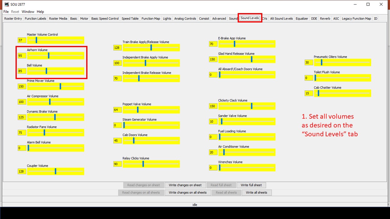
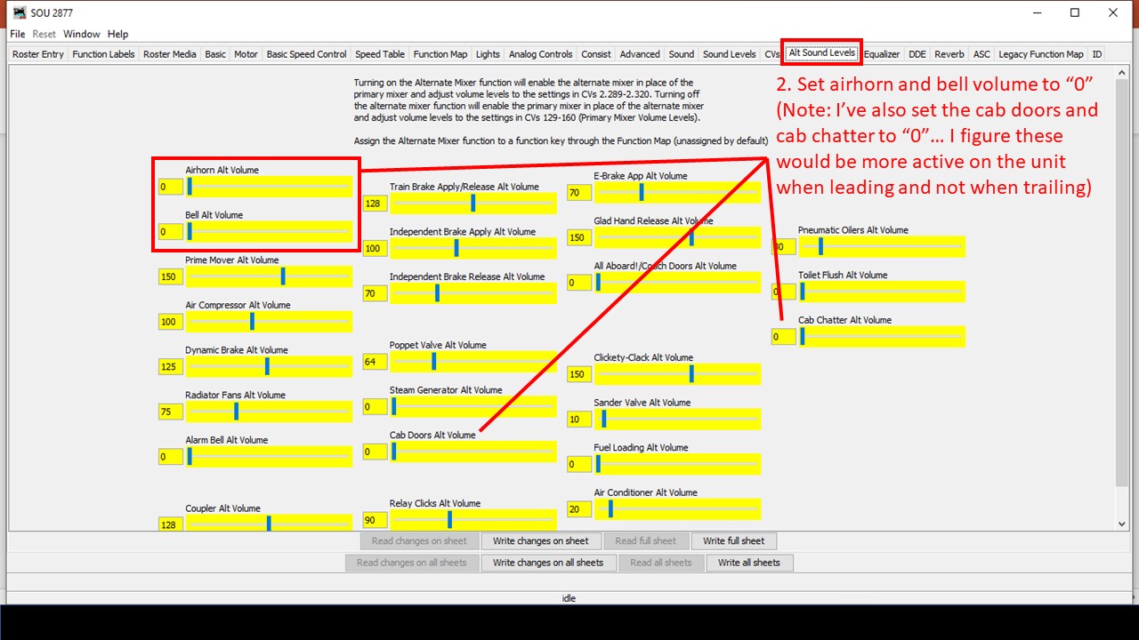
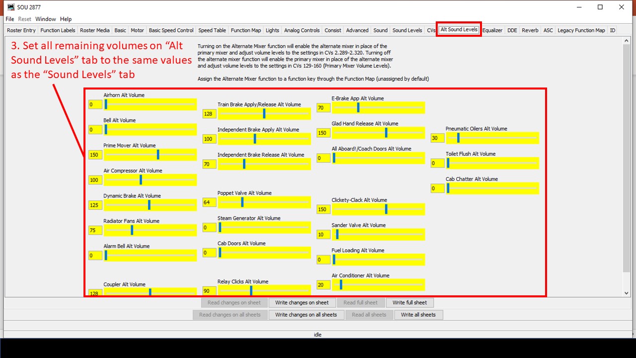
Soundtraxx Tsunami 2 decoders have an “alternate sound mixer” designed to make it easy to select a new set of alternate sound levels with the press of a function button. Additionally, the “function mapping” in Tsunami 2 decoders allows you to set any function to operate automatically when the command station commands the decoder in “forward driving,” “reverse driving,” “forward driving,” or “forward standing” conditions. The trick is to set all the alternate sound levels to match the primary sound levels EXCEPT the horn and bell which are set to volume “0,” then use the function map to configure the alternate mixer to operate any time the decoder is moving in the trailing direction (forward or reverse based on how it’s sitting in the consist), and finally to set up the decoder to “respond to consist address” for horn and bell functions. When you set up the locomotives on the ends of the consist in this manner, it has the effect of silencing the horns and bell when the locomotive is trailing and not leading. Here are the steps in JMRI.

Consisting for horns and bells 1
Step 1. Set the sound levels in the primary sound mixer


Consisting for horns and bells 2
Step 2. Set the horn and bell to “0” in the alternate sound mixer


Consisting for horns and bells 3
Step 3. Copy all other sound volume values from the primary to the alternate sound mixer


Consisting for horns and bells 4
Step 4. Set up the “alternate mixer” to operate with forward or reverse direction (the direction in which it’s trailing in the consist)


Consisting for horns and bells 5
Steps 5-8. Set up the advanced consisting so directional lights and functions for horn and bells “respond to consist address” and enable the automatic functions


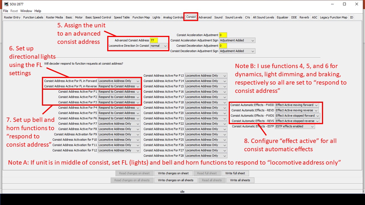
Some of the settings will depend on where the locomotive is in the consist and whether or not its on the end. For a locomotive in the middle of the consist, you can either set the decoder’s light, horn and bell functions to “locomotive address only” in the consist tab, or you could place check marks in all four columns in the function map (forward driving, reverse driving, forward standing, reverse standing) so only the alternate mixer with zero volume for bells and horn are used. If you change the orientation of the locomotive, you may need to change the FL settings in the “consist” tab and swap from “forward” to “reverse” check marks in the function map. Also, if you’re using a locomotive on the end that doesn’t support an alternate mixer (like the Soundtraxx Econamis I have in some locomotives), then you’ll need to pick just one of the locomotives to “respond to consist address” to provide the horn and bell for the whole consist and disable the directional checks in the function map.

That’s it! Now when you run a throttle using the advanced consisting address, the lights on the ends will be directional, AND only the horn and bell of the leading unit will respond to the throttle’s horn and bell functions no matter which direction you’re running. Click on the video at the top of the page to see this in action, and if you’ve got some even better tips and tricks for this, please leave them in a comment below!

Farewell to the Mighty Z

DCS50 Zephyr
This Digitrax DCS50 Zephyr has served me faithfully for more than a decade on two layouts

***Update Oct 22, 2022. The Zephyr is not yet gone, and I may just keep it. I’ve figured out that I can still use it to turn track power on and off, even in booster mode, and the odd scrolling LEDs that come with placing the unit in booster mode aren’t quite as annoying as I remember. It also seems kinda handy to be able to quickly punch in a loco address and run a locomotive with the Z when doing things like speed matching… so, even though it’s no longer my command station, it may just stay right there on the fascia.***

This past Wednesday marked a milestone on the layout–it was the last time my layout was controlled by my venerable and dependable Digitrax DCS50 Zephyr! The “Z” is known as an entry level system, but it’s historically been my favorite to use as a command station because it’s very easy to operate and made a great stationary controller for creating consists and programming decoders. On both my previous layout and this one, I used a specially made box created just to mount the Z on the fascia in a convenient spot. The Zephyr’s 2.5A were never enough to power my entire layout, so there’s been an old DCS100 command station/booster serving as the booster behind the scenes, but the Z has always been the command station, and I’ve always had fewer than 10 locomotives on the layout at once, so the “slot” limitation has never been an issue.

Two things have happened recently that precipitated a change away from the Zephyr. First, thanks to my adoption of sound decoders and their braking features in all locomotives, I switched from “universal consisting” (command-station consisting) to “advanced consisting” (decoder consisting) to be able to control functions in all decoders simultaneously, so I can do all my consisting in JMRI instead of in the command station. While this method takes up even fewer slots in a command station, it also eliminated the need to create consists using the Z, one of its greatest strengths. Secondly, my old DCS100 has been getting more and more finicky over the years, often being disagreeable and “forgetting” its a booster. This never created any operational problems, but it was a constant source of angry beeps from the DCS100. I had a few options. First, I could just revert to using the DCS100 and upgrading to a newer advanced throttle (it came with an ancient DT100), but the DCS100 was starting to show its age. I also played around with a new generation Zephyr Express (DCS52), but I found the screen and buttons too bright (I want to run night operations), and the DCS100 REALLY didn’t appreciate working with the new Z, and it was more difficult than I’d hoped to get them to play nice together. Ultimately, I decided that the best answer would be to just upgrade the whole command station/booster combo.

DCS210 on the layout
The new DCS210+ in its spot on the staging level

I ended up going with the Digitrax Evolution Express (EVOX) which includes a 5A DCS210+ booster, 100-slot command station, a USB interface, and an a DT602 advanced throttle to control everything. It’s plenty of power for the layout, and I’ll never need the additional capacity of the top end command station. I splurged on the duplex radio version because I figured it would be worth it to upgrade my 2-way radio system to the newest receiver (UR93), and I wanted to preserve the ability to use the DT602 wirelessly, even if right now it’s serving as a glorified power button. Installation of the new system was easy, and everything works like a champ! I’ve also now got a spare command station, spare 5A power supply, and spare duplex radio receiver if I need them. I’ve also got a backup method for connecting my Digitrax to JMRI, even though for now I’m sticking with my old PR3 rather than using the DCS210+ USB port… it’s working well, don’t mess with it!

Anyway, I didn’t want to let this moment pass without giving a big shout-out and thanks to my Zephyr for the many years of faithful service on the layout. I don’t know many who use a Z as the command station for a good-sized, serious layout, so I was happy to be a long-time advocate! I already miss one simple thing: the ability to just push a button on the Z to turn the track power on and off. I’ll say farewell, though I have no plans to actually get rid of my Z any time soon… maybe I need a stand-alone programming station… hmm…

One final thing. If you’re trying to turn the track power on or off using a DT602 super throttle, and you can’t get the soft keys for track power to stay there long enough for you to actually push them, you need to press on the LEFT side of the power button and not in the middle. Might just save you a help-desk ticket with Digitrax… not that this happened to me.

Loconet Functional Diagram - St Charles Branch Aug 2022
Here’s the updated functional diagram of the Digitrax system on the layout


Sound for a Proto GP7

You may remember Southern GP7 2187, a Proto GP7 I finished last summer. Well in addition to fixing the railings and steps for my 1970 timeframe (black and white instead of yellow), I decided to install sound. Now sound is something pretty new and intimidating to me, but after running a couple factory-equipped sound locomotives, it was tough to go back to no sound. I finally decided to just jump in! There are many great sound decoders out there, and everyone has their preference. I won’t claim to be an expert, but after doing some research, I decided to start with some Soundtraxx Econami decoders. As you might guess from the name, these are “budget” decoders that run about 2/3 the cost of a full-featured sound decoder from any manufacturer. The Econami is pretty basic, but it does have the key features I need, and it uses the same basic sounds as the more expensive Tsunami 2s. Best of all, the Econami Diesel version allows the user to select from a handful of prime movers including everything I need for my first-generation fleet: the Alco 244 for RS3s and the non-turbo EMD 567 for Fs, GP7s and GP9s.

21-pin NEM DCC connector mapping
Basic mapping of a 21-pin connector for DCC (use at your own risk)

Soundtraxx makes two versions of the diesel Econami, the larger ECO-PNP and the smaller 21-pin ECO-21PNEM. I picked up a couple ECO-PNPs, one of which was intended for 2187, but once I got the decoder, it was obvious that it wouldn’t fit without major modification to the large metal weight–I needed something smaller. After installing the PNPs in an RS3 (just barely) and an F3A, I decided I was happy with the sound produced by the Econami and a pair of mini cube speakers, so I looked to see if I could install the smaller 21-pin decoder in the GP7. The 21-pin arrangement is newer, and I was surprised at how tough it was to find a cheap 21 pin harness I could wire into the locomotive. You can find cheaper ones in Britain, but it was going to cost me an extra $20 to get one in the states–what’s the point of using the Econami if a simple harness was going to eat up all the savings?

Sawing the Proto weight to make room for speakers
Taking 8mm off the height of the weight in the nose of the Proto GP7 to make room for speakers

So, could I get the 21-pin Econami to work without a harness? While it was a little tough to find info, I finally figured out the mapping of the 21 pins (thankfully German shares some commonality with English…). I knew it wouldn’t be practical to solder directly into the decoder (the pin holes are tiny and close together), but I thought I might be able to shape the wires to act as pins, so I ordered up an ECO-21PNEM. What I found was I could tin the wires on the locomotive, cut the end so about 2mm of metal was exposed, and then carefully insert the wire into the correct pin hole. While the connection is not bulletproof, it’s snug enough that the wires don’t come out easily, and if you can push the wire in until the insulation is flush with the board, there’s little chance of a short. For the extra wires (e.g., speaker wires), I used 30 AWG stranded wire tinned with solder–I had to use a little extra solder to get a snug fit, so a 28 AWG wire would probably work as well. Once I verified everything worked, I used a piece of electrical tape to hold the wires down and in-place.

Proto GP7 Econami ECO-21PNEM installation
Using a 21-pin Econami decoder without a 21-pin harness

Now for the speaker. Unfortunately, I decided to use the large clear plastic blocks for the number boards and lights, so the little room that was left in the top of the shell was taken up. I decided the best course of action was to take the weight off and remove about 8mm of metal height from the nose section with a hacksaw. After filing the cut clean, I was ready to install the speakers. I’m using the 11 x 15mm cube speakers made by Loksound. You can find a lot of sources for speakers this size, but I love that the Loksound versions come with different baffle arrangements including both short and tall and a base to install two speakers side-by-side (my preference). I built a double baffle with the short walls using CA and connected the speakers in series (16 ohms impedence). Yes, the decoder is 8 ohms and the speakers are 16 ohms. My research leads me to believe this is not ideal but is acceptable as long as I don’t run the amp at max, which I don’t–if you have a good technical reason why this is not a good idea and will damage things in the long-run, please feel free to post a comment!

So, in the end, I was able to fit a sound decoder and two small speakers into the Proto GP7 with just a small, one-cut modification to the body weight, and I’m really happy with the sound! I’ve got a Soundtraxx Tsunami 2 EMD diesel decoder now as well, so I’ll do a comparison at some point and let you know how I think the Econami compares. For now, I’ll enjoy the chugging sounds of the EMD 567 and hauling coal hoppers interrupted occasionally by the chimes of a Nathan M5! St Charles is now a much louder place.

Lanyards for Wireless DCC Throttles

Throttle Lanyard for Digitrax UT4
Wearing a UT4 throttle

I’m continuing to capture little projects on the layout as I think about them. I bought a “spare” Digitrax UT4D utility throttle recently and was reminded of the modification I’ve done to all my UT4s to make them more user friendly. I use the UT4D 2-way radio throttles because they’re light, very easy to use, and the wireless makes them very convenient to use anywhere on the layout. Despite this convenience, there’s still one major problem with the UT4 (or any walk-around throttle for that matter)–where do you set it when you’re not using it? This is not a problem when you’re done with your train as I’ve got plenty of throttle pockets along the fascia in which to stash them and plug them in to keep the batteries from draining. But what do you do with the throttle when you need your hands for other chores like uncoupling and paperwork? This is a major consideration for a switching oriented layout like the St Charles Branch.

On my last layout, I came up with the idea of attaching a simple anchor for a clip-style lanyard. It does require drilling a couple holes into your throttle, but it’s only through a narrow part of the plastic casing and into the battery compartment, so it’s not a threat to the throttle’s electronics. The anchor is made from .025″ steel music wire which you can pick up at most hobby stores. Lanyards come in many styles, but I use the lanyards with the “bulldog clip” that doesn’t swivel and provides a very easy pinch mechanism to attach and release the throttle such as the ones in this link (yes, I get a little commission if you use this link, and it doesn’t cost you anything extra to use this link–thank you).

Here are the rest of the steps:

  1. REMOVE THE 9V BATTERY FROM THE UT4!!!
  2. Cut a piece of .025″ steel wire about 2″ long
  3. Bend into a squared-off “U” with the bottom about 1/2″ wide (just wide enough for the lanyard clip with about 1/32″ of slack) and each side about 3/4″ long
  4. Mark the bottom of the UT4 throttle case for drill holes–make them the width of the U and centered within the “groove” of the plastic
  5. Drill 2 holes into the case–use a drill bit that’s slightly oversized so the wire slides freely without rattling
  6. Insert the wire “U” into the case and attach a lanyard to the bottom of the “U”
  7. Push the “U” into the case as far as it will go and then back off just slightly (“U” extends approximately 1/8″ from bottom of throttle case)
  8. Bend the ends of the “U” that are inside the case outward to mark where the bends need to be
  9. Remove the lanyard, push the “U” as far as it will go into the case and bend the ends inside the case with needle-nosed pliers until they are parallel with the case bottom
  10. Extend the “U” outside the case then reinsert 9V battery, pushing it up against the top (antenna side) of the throttle as far as it will go

You should now have a clip anchor that retracts into the little groove when the throttle is set down on top of it that extends just enough to allow a lanyard to attach when picked up. It doesn’t get in the way of anything if an operator chooses not to use a lanyard, and it provides a secure way to let the throttle dangle when not needed. I’ve been using these mechanisms for years and have never had a catastrophic throttle drop (your results may vary ;-). Similar techniques may work on other throttles as well, though I’ve only tried it on the UT4D.

Major Milestone – Lower Level Track Complete

L&N taking a test spin
L&N RS3 100 takes a trip around the wye at St Charles
St Charles yard tracks complete
Completed St Charles yard tracks

Hit a major milestone yesterday: the lower level tracks are complete! I completed the first scene, the end of the line at the Mayflower tipple, several months ago, and the last few months I’ve been working on the long scene at St Charles. St Charles – the branch’s namesake – was home to a wye, a depot, a couple small tipples, and a three-track “yard.” St Charles was also home to a mine run when the tipples were busy, so this is the central scene on the layout. All told, the St Charles scene is about 26 linear feet long and required 14 hand-laid switches (about 1/2 of them curved) and a couple of bridges.

Electrically, I made the entire Mayflower branch an auto-reversing zone for the wye. Can I just say the On-Guard AR solid-state DCC auto-reversers are awesome? The switching of polarity on the wye is absolutely seamless and unnoticeable–I highly recommend them! I also isolated a single rail of both the “house track” and “engine track” in the middle of the wye and will place a switch on the fascia. This will allow me to turn the power off to the two tracks that would hold idling power in case any sound locomotives get annoying. Next step is fascia and switch controls.

DCC Zones – Planning for Future Operations

This post is less of an update and more of an effort to chronicle a minor but important part of layout construction: DCC track bus planning. Installing DCC has two major components, the first is wiring up the DCC system with its command station, booster(s), throttle panels, computer connections, wireless throttle receiver, and network cables–I covered the installation of the DCC and logical connections of the DCC system here. The second component of DCC is installing the wiring for the track which includes electrical buses, circuit breakers, and dividing the layout into zones which I’ll cover here. Even if you don’t plan to use circuit breakers, its still a great idea to “future proof” your layout by wiring for zones–you can always tie the zones together at the booster, but you don’t want to be installing new buses and feeders under finished scenery. These zones will also help with electrical troubleshooting if you can’t find a short–you’ll at least be able to isolate it to a smaller section of track.

DCC indicator light on UP5
This UP5 panel’s Loconet light is connected directly to the booster (note the “M” label for “master”)

My layout is small enough to easily be powered by a single 5A DCC booster, in my case, an old Digitrax DCS100 Chief acting as a booster (a DCS51 Zephyr is the command station). At most, I’ll have 3 trains and perhaps 6 locomotives running at any given time. The DSC100 can handle this current easily, but with circuit protection provided by only the booster, if any one locomotive runs against a switch and shorts on the frog, power for the entire layout and all trains shuts off. The solution? Dividing the layout into zones and using solid-state circuit breakers!

I already needed at least three zones on the layout because I have two reversing loops which need to be isolated from the main bus and powered through an auto-reversing circuit breaker. In my case, I use the On-Guard AR reversing breakers from DCC Specialties. Although a tad on the expensive side, the solid-state AR circuits are rock solid and work more reliably than their analog counterparts, especially with the current draw of sound locomotives. Aside from the reversing zones, I decided to divide the remainder of the layout into 3 additional zones, one per level. How many zones you use is a balance of cost and functionality–too many, and the cost quickly gets out of hand along with the wiring (each zone needs its own wiring bus), too few, and operators causing short circuits will quickly ruin the fun of other operators in the same zone.

With my max of three trains in mind, I drew zone lines primarily to ensure each train would be in its own zone most of the time. Consequently, the zones are different sizes based not only the amount of track it powers but the operating locations for the trains. For example, zone 3 is the largest on the layout and powers not only the entire upper deck but the helix between the lower and upper decks as well. That’s a lot of track, but only one train at a time will venture to the upper deck, so it can be large. The main level is two zones with one covering the wye and yard at St. Charles, and the second (a reversing zone) covering the branch to Mayflower–there will often be a train at St Charles while another works the Mayflower Branch. Finally, I made the staging level its own zone (along with a second reversing zone) so that operators moving things in and out of staging won’t impact operators on the visible portion of the layout.

Once I knew where the zones would be, I ran an electrical bus from the vicinity of the booster all along the benchwork where the tracks of that zone would go. I’m all about overkill here, so I use household Romex 14 gauge copper wiring that I pull out of the sheath. I drill holes and run the black and white wires through the benchwork about 4″ apart. One important step is to LABEL THE BENCHWORK with a Sharpie every few pieces of wood, especially if you have multiple buses running side-by-side, so you don’t become confused as to which track you’re hooking up to what zone–if you mess this up, your track could be wired to multiple zones simultaneously and eliminate any benefit of electrically isolating the zones. At the ends of the run, I just wrap the lines around a drywall screw. If I need to run a bus in two directions, I just make a junction and join the three wires together with a wire nut, just like I would do with household wiring.

Pigtails for the DCC bus
Pigtails on the DCC bus, note the zone IDs (2 and 2R) marked on the benchwork

I strip about 1″ of insulation off each wire about every 2-3′ where it will connect to track, and I wrap a 4″ section of the uninsulated ground wire from the Romex around the bare spot about 3 times leaving 1″ or so hanging off both ends. A little solder keeps this pigtail in place. I’ll offset the white- and black-line pigtails by about 4-6″ horizontally in addition to the distance between the wires to minimize the risk of shorts. These pigtails become the connection points for track feeders using wire nuts. Of course, you’ll need to physically separate the tracks between zones by either cutting gaps in the rails or using a plastic insulating joiner. Be sure to overlap your gaps by 3/4″ – 1″ for zones connected to an auto-reverser!

Between the bus for each zone and the booster is a circuit breaker, in my case a PSX-3 (essentially 3 PSX-1s) from DCC Specialties (I covered how to program these with a DCS51 here). Like the auto-reversing breakers, the PSX breakers are solid-state and are well worth the money over analog breakers, especially if you’re running sound locomotives. I have been extremely impressed with these units so far! The PSX design makes it easy to daisy-chain multiple breakers with just one set of wires to the booster. The only split I had to make was after the PSXs when I had to run the last booster connection off the PSX to the two AR circuits. To make the connection to the buses easier, I made a simple “panel” on part of the benchwork where the 14 gauge wires for each bus come through, get wrapped around a drywall screw, and have the ends exposed for connection to the PSX via smaller wires connected with wire nuts.

DCC zone indicator lights on UP5
Zone 1 and 2 indicators using UP5 Loconet lights

A final step for me was figuring out a way to monitor each zone to know what’s active and what’s shorting out. It’s more difficult to detect a short with the PSX than the DCS100 because the booster makes a distinct noise when it’s reacting to a short, but the PSX is silent. For monitoring, I turned to the Digitrax UP5 universal interconnector panel. I have five of these panels at various spots along the fascia of the staging level for connecting throttles, and each has a “track status” light that can be wired to the track bus. I chose one in proximity to each zone to be the “zone indicator”, labeled with a sticker for the zone number to help me remember, and wired it to pigtails of the corresponding track zone. This way, if a short occurs, only one light corresponding to the affected zone will go out to aid troubleshooting. I wired the UP5 adjacent to the command station and booster directly to the booster wires (no circuit breaker in between) and labeled it to be the master monitor–if it’s on and everything else is out, it tells me the problem is somewhere in the circuit breaker wiring.

Finally, I drew pictures (the ones seen here) of the zones on top of a layout diagram to help me remember exactly where the zones go, and I placed this in my layout binder with all the other helpful information on the layout. This wiring took a good bit of time to plan out and install, but now the layout has the robust electrical backbone to make for smooth connections, easier troubleshooting, and ultimately more fun for operators.


All the Boring Stuff – Wiring, Wiring, Wiring

I haven’t added an update for a while because the layout doesn’t really look any different. That’s not to say I haven’t been working, it’s just been all the boring stuff – wiring. It may be boring, but if you want your layout to run well, it’s doggone important, so it shouldn’t be left as an afterthought.

Power switches for staging tracksFirst, I corrected an issue I first noticed when running trains around the staging level – sound! I never ran sound locomotives on my previous layout, and now that I’ve got a few, I noticed how annoying it is to have diesels sitting in staging making idling noises that are easily heard throughout the room. These trains are supposed to be dozens of miles away, and I don’t want to hear them while they’re in staging. Of course, there’s the option to “mute” a sound locomotive temporarily, but I don’t want to force operators to go through an entire consist muting and unmuting every time they pick up or drop off a train in staging (and every time a short occurred, all the sound would come right back on anyway). For a solution, I went “back to the future.”

I installed a small SPST toggle switch (picked up 20 for cheap on eBay) for each staging or locomotive track (9 total) on the fascia where the track diagram will be. Unfortunately, this meant pulling dozens of feeders from the staging tracks and running a secondary bus for one rail under each track that’s connected to the switch. Thankfully this didn’t involve any de-soldering because all my feeders are connected via wire nuts. Now I can turn off the power to any staging track with sound locomotives until they’re needed, and all the operator has to do is flip a single switch. Old school “electrical block” solution to a DCC problem.

PSX3 InstallationWhile I was at it, I broke down and ordered a DCC Specialties PSX-4 solid-state circuit breaker to go with my On-Guard-AR auto-reversing circuit breakers. I’ve been planning to do this all along and wiring for multiple zones, but after reading through the PSX documentation, I discovered my understanding of the PSX-4 and how it interacts with AR breakers was a little lacking. I didn’t know that the AR breakers should not be wired off a PSX zone but directly wired to the booster themselves. Turns out with the two reversing zones already protected by an AR circuit breaker, I really only needed a PSX-3 because I only have one non-reversing zone per level (1=staging, 2=lower level, 3=upper level, 1R=staging reverse tracks, 2R=St Charles wye to Mayflower). “Snap” – “hey look, now I have a PSX-3 and a spare PSX-1”. . . smart DCC Specialties! Not gonna lie, it was a little confusing to program the PSX to work well with the AR breakers using the Digitrax Zephyr, but I finally figured it out:

  • Set the Digitrax booster to .5 sec short circuit trip using booster instructions (CV 18 to “c” on my DCS100)
  • Solder the Digitrax jumper on each PSX zone per PSX instructions
  • Set the PSX to programming mode via the jumper per the PSX instructions
  • Ignore the part about setting the PSX address unless you need the PSX to respond to “on/off” or other special commands from the DCC (If you just need it to be a circuit breaker, you don’t)
  • Connect a single PSX zone directly to the Track A / Track B from the Zephyr
  • Turn the track power on on the Zephyr
  • Put the Zephyr into “OPS Programming” mode
  • Select CV55 (“CV”, “55”, “CV”)
  • Press “1” and “CV-W” (add delay to the PSX so the AR zones will trip/reverse first)
  • Select CV65 (“CV”, “65”, “CV”)
  • Press “80” and “CV-W” (set delay to 10ms which works for my setup)
  • If Zephyr shows “Busy,” exit programming mode and try CV65 steps again
  • Set PSX to ops mode via the jumper per the PSX instructions
  • Repeat steps for additional PSX zones

Lower Level Wiring BusI encourage you to read all the instructions first and choose your own adventure–just sharing what worked for me.

Finally, before I lay subroadbed and track for the lower level, I had to add the wiring bus, or in this case, two wiring buses. Two are needed because the St. Charles wye needs a reversing circuit, and the reversing district carries over all the way to Mayflower. Lots of drilling holes, cutting open Romex, and pulling heavy gauge wire through. I still have to make the little pigtails for feeders, but it’s mostly done. Shouldn’t be long before I’m laying track on the main level!

Layout Wiring

Layout wiring on the St. Charles Branch is simple yet very robust using common household wiring supplies. First, I’ve divided the layout into six blocks: four “main” blocks (1. Staging, 2. St. Charles, 3. Mayflower, 4. Upper Deck), and two reversing sections (1R. Staging loop, 2R. St. Charles Wye). Even though I don’t have a power block distribution circuit yet (like a PSX4), I’m wiring the layout for that eventuality and just tying all the blocks together at the command station as an interim.

Feeders and Bus Pigtail Connections
Feeders are connected to the wiring bus via wire nuts connected to pigtails along the bus.

The bus wiring for each block is copper Romex wiring. . . that’s right, Romex, the 14 AWG copper wire you use to wire household sockets and light fixtures. It’s overkill, but it’s easy to find, comes in long lengths, and the current loss for DCC applications is pretty much zero. I strip the outer sheathing, remove the bare ground wire, and use the black and white wires. I run them under the track through holes in the benchwork separated by about 2.5″. Lesson learned: if running the bus for two blocks side-by-side, make sure you label each about every other piece of wood to avoid cross-wiring blocks later.

I drop feeders at least every 5 feet, so on every 2-5 feet of bus wiring, I’ll strip off about 1″ of insulation and make a “pigtail” if you will using a length of 4″ of the bare copper wire (Romex ground wire) wrapped tighly around the bus core about 3 turns and soldered. I leave about 1″ of copper sticking off either end and cap it with a wire nut. I separate the pigtails for the white and black wires by about 4-6″ to avoid accidental contact of exposed wire.

Wiring Feeders
Wiring feeders from the rails to the bus under the layout. The gray plug marks the spot of connection to make it easy to cut wires to the right length.

Finally, the feeders. As mentioned, I try to drop them every 3-5 feet of rail. For bulletproof operation, every single rail on the layout is directly connected to the bus either through its own feeder or a single soldered joint to the rail next to it that’s connected to a feeder (no trusting rail joiners to carry current and signal). I drill the holes first, then drop pieces of 18 guage stranded wire through to connect to the bus. You’ll notice in the picture above the layout the little gray plug. I use this to mark the location of the pigtail under the layout so I can accurately cut the feeders to length, leaving about 1.5-2″ extra length to account for vertical distance through the subroadbed and some wiggle room for orienting the feeder to fit into the pigtail. Because I hand-lay my switches, I need a LOT of extra feeders for the point rails and frogs (connected to switches under the layout).

To make sure I hit all the holes, I leave the sawdust from drilling them in-place until all feeders are in. I also work one color at at time; white for one rail, red for the other. Once all the feeders of one color are in place, I’ll tin them with solder and solder each to the rail. Under the layout, I’ll gather together 2-3 feeders, twist them together, and tie them to the pigtail using a common wire nut (size depending on the number of wires being tied together). A little tug ensures they’re solidly in-place.

I’ve found this method creates rock-solid wiring that’s easy to modify and troubleshoot–just disconnect and reconnect the wire nuts as needed. This method also works perfectly with Digitrax DCC which prides itself on picking a slower data rate that works well with non-high-speed wiring. If using on a different system, I recommend doing some testing first.

Southern Staging Tracks Complete

Another milestone today–the Southern Railway staging yard tracks are now complete! The yard, representing Appalachia, Virginia, consists of 8 hand-laid switches and about 40 pieces of flex track. The yard is three tracks on a reversing loop, one through track for mainline running (which can be used as a fourth staging track), and two short storage tracks for extra locomotives.

Southern Staging Tracks Complete
The Southern railway staging tracks representing Appalachia are now complete. The tracks form a reversing loop under the main helix.

The shortest staging track is about 21 feet long–that’s long enough for three locomotives, a cab, and 35-45 hoppers. . . should be plenty. A second, 4-track stub-ended staging yard with shorter tracks will help with L&N trains and holding excess cars.

Staggered joints for reversing loop
Here’s one of the insulated joints going from the yard lead to a staging track on a reversing loop. I offset the joints about 1″ which is recommended for better performance of the auto-reverser.

I also fixed a problem with this website where the smaller images weren’t linked to their full-size cousins–that’s remedied now if you’d like to get a closer view of previous post pictures. Thanks to Stuart Thayer for pointing that out!

DCC Installed

Digitrax Setup
Key Digitrax components on the layout including a DCS51 command station, PR3 computer interface, DCS100 (acting as a booster), and power supply

The last couple of weeks I’ve been working on the fascia and wiring for the staging level, and I’ve also installed the DCC system. It’s a lot easier to install when there isn’t a lot of layout in the way, and most of it resides on the bottom deck anyway.

I’m using the Digitrax DCC components from my last layout. While I have an upper-end DCS100 “Chief” system, I’m actually using a smaller, entry level DCS51 Zephyr Xtra as my command station. While the Zephyr doesn’t have the same functionality as the Chief, it’s got everything I need, and it’s much simpler to operate. Like my previous layout, I’ve mounted it on the fascia where it’s easy to access and can be used as a throttle for the staging tracks or for smaller visitors.

Throttle Pocket
One of the simple throttle pockets for the Digitrax UT4D wireless throttles. It’s designed to hold two throttles while preserving batteries and protecting buttons.

The rest of the throttles are UT4D 2-way wireless throttles connected through a UR92 wireless receiver/transmitter. Even though everything’s wireless, I still use several UP5 throttle plug-ins around the layout. This allows someone else to bring and use their favorite Digitrax throttle, and it allows an ops session to go on if the wireless is acting up. Each of the panels has an adjacent throttle pocket that perfectly fits the UT4D throttles (those who visited my last layout will recognize these). This not only gives the operators a convenient place to set the throttles, but it protects the buttons and also promotes the plugging in of throttles when not in use to preserve batteries.

I’m using three sources to power components. The first is straight wall power, and this powers the UP5 panels to supply keep-alive power to the throttles (preserves batteries while the layout is off). The second is switched power for the DCS100 and UR92, and the third is switched power for the Zephyr command station and a PR3 computer interface. I kept these separate so I could turn on just the “Z” and PR3 when I’m programming locomotives.

Loconet Functional Diagram
Functional diagram of the Digitrax setup on the layout

One lesson I learned from my last layout was to keep a functional diagram of the Digitrax setup so I could easily determine how the components are wired together even when they’re covered by the layout–it’s a great aid in troubleshooting!