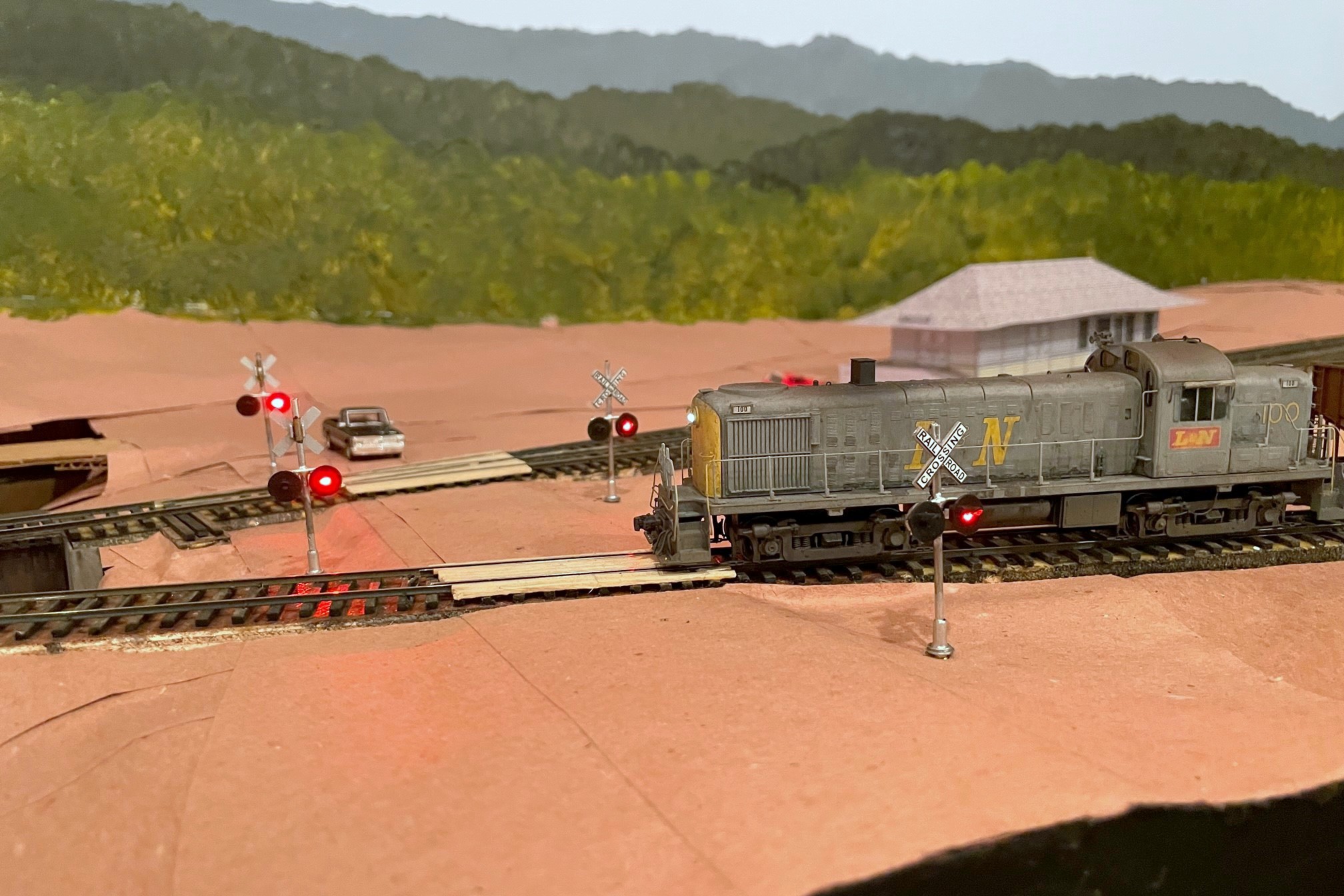
The CV Local led by L&N RS3 100 crosses Bonny Blue Road with its newly installed crossing flashers
Many of the grade crossings on the St Charles Branch didn’t have flashing signals and were protected by flagmen or fusees (see how I simulate fusees here), but a few of the more prominent crossings were protected by automatic flashing signals and bells. One of those crossings is Bonny Blue Road which crossed two legs of the wye in St Charles. I was looking for a way to make these signals work automatically with nothing required of the crews (beyond sounding the horn for the crossing) and no hardware needed on any rolling stock. I quickly settled on using IR sensors mounted near the tracks to trigger the circuits required for the crossing. While many of the major manufacturers of railroad electronics offer circuits for flashers and for triggering based on sensors, there seemed to be a lack of good, simple options for the sensors. So I did what many of us do when we’re looking for something–I turned to eBay.
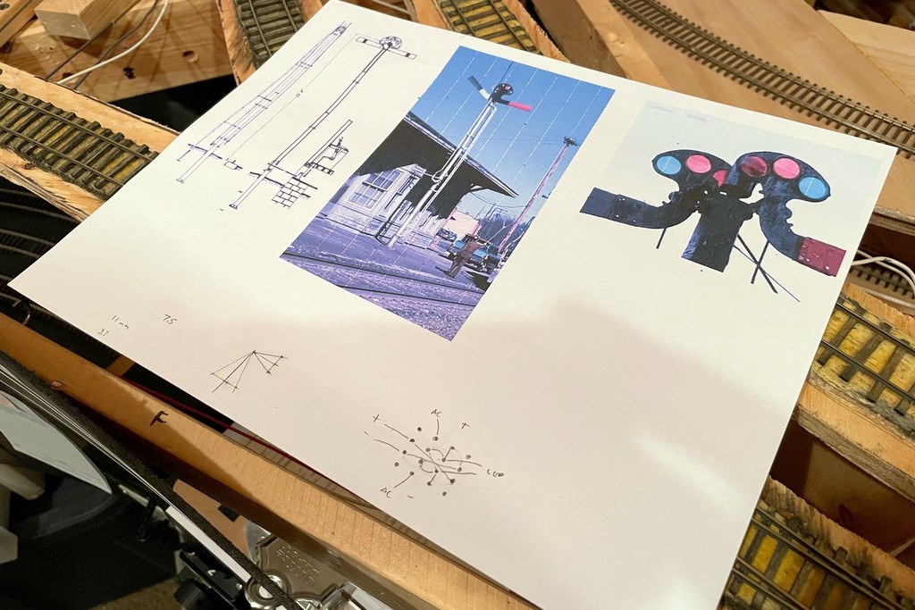
I found a lot of products for flashing crossing signals, but one it particular caught my eye. A company called “WeHonest” was offering what looked to be decent looking LED signals that came with a flashing circuit for a very reasonable price. Being a little suspect of a foreign company calling itself “WeHonest,” I needed four signals, so I ordered a couple sets and hoped for the best. I ordered the signals with two heads instead of four (front and back) because my signals would only been seen from one direction, and the ones with four heads looked too thick front-to-back (I plan to add dummy heads on the back later). When they arrived a couple weeks later, I was impressed with the quality for the price. The lettering is easily readable, the construction is mostly metal, and the size and shape are good for HO scale. I had to clean up some areas of the metal crossbucks, and some of the silver paint flaked off, but these were easy fixes. I initially hooked up the flashing circuit to a pushbutton on the fascia, and the flashing circuit worked flawlessly and controlled all four signals in a synchronized manner.
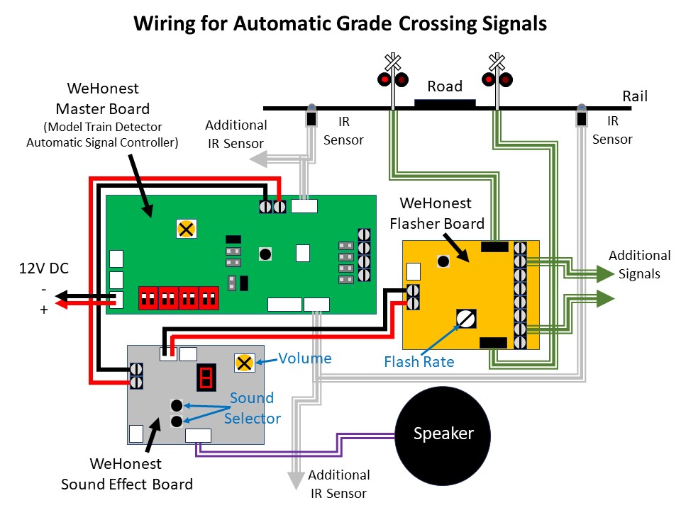
The signal piece was solved, so now I needed a way to automatically control them. My confidence in “WeHonest” was bolstered, so I explored their options. They offer a “model train detector automatic signal controller crossing system trigger etc” (also called a “master board”) which shows a diagram of how it can be configured to trigger a grade crossing flashing circuit using simple, single-unit IR sensors that don’t require a broken path. I also needed a circuit that could support four sensors due to the tracks that would trigger this grade crossing, and while the board only supports two sensors, their diagrams show that you can connect more sensors via separately available splitter cables. They also offer a sound effect circuit with multiple grade crossing signal bells (and a rooster). I ordered a master board, sound effect board, two splitters, and some additional IR sensors.
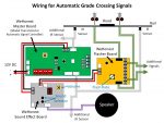
Wiring diagram showing the connections needed between the three circuit boards, signals, and sensors
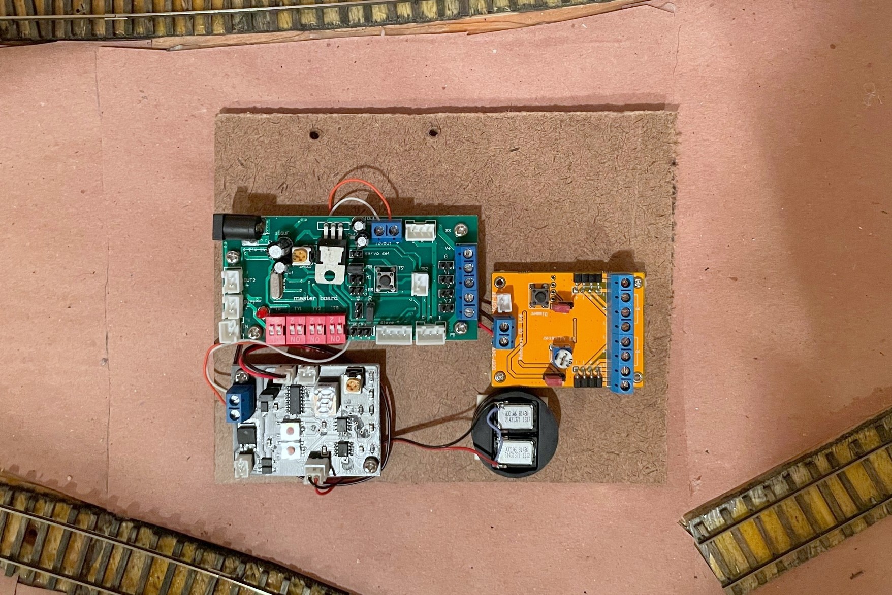
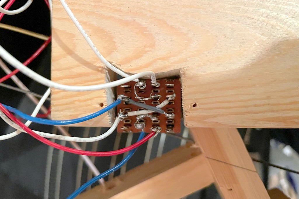
The documentation you see on eBay is all you get, so it took some studying and tinkering to set things up, but it wasn’t difficult. The basic idea is the master board is connected to 12V DC and the IR sensors. The sound effect board and flasher circuit are daisy chained off the 12V DC “output” side of the master board which is only live when the IR sensors are triggered. The only surprise on wiring was there are no normal contact screws for the 12V DC input, only a plug for an adapter and a specific connector type (both of which are sold separately). I found a plug off an old RC helicopter I disassembled years ago that did the trick. I mounted all three circuits and the speaker on a piece of masonite to keep the wiring tight and organized. Rather than use the supplied speaker, I attached a pair of baffled cube speakers I had pulled out of a locomotive when I replaced it with a Scale Sound System speaker.
I mounted all three circuits and the speaker on a single piece of masonite to declutter and protect the wires
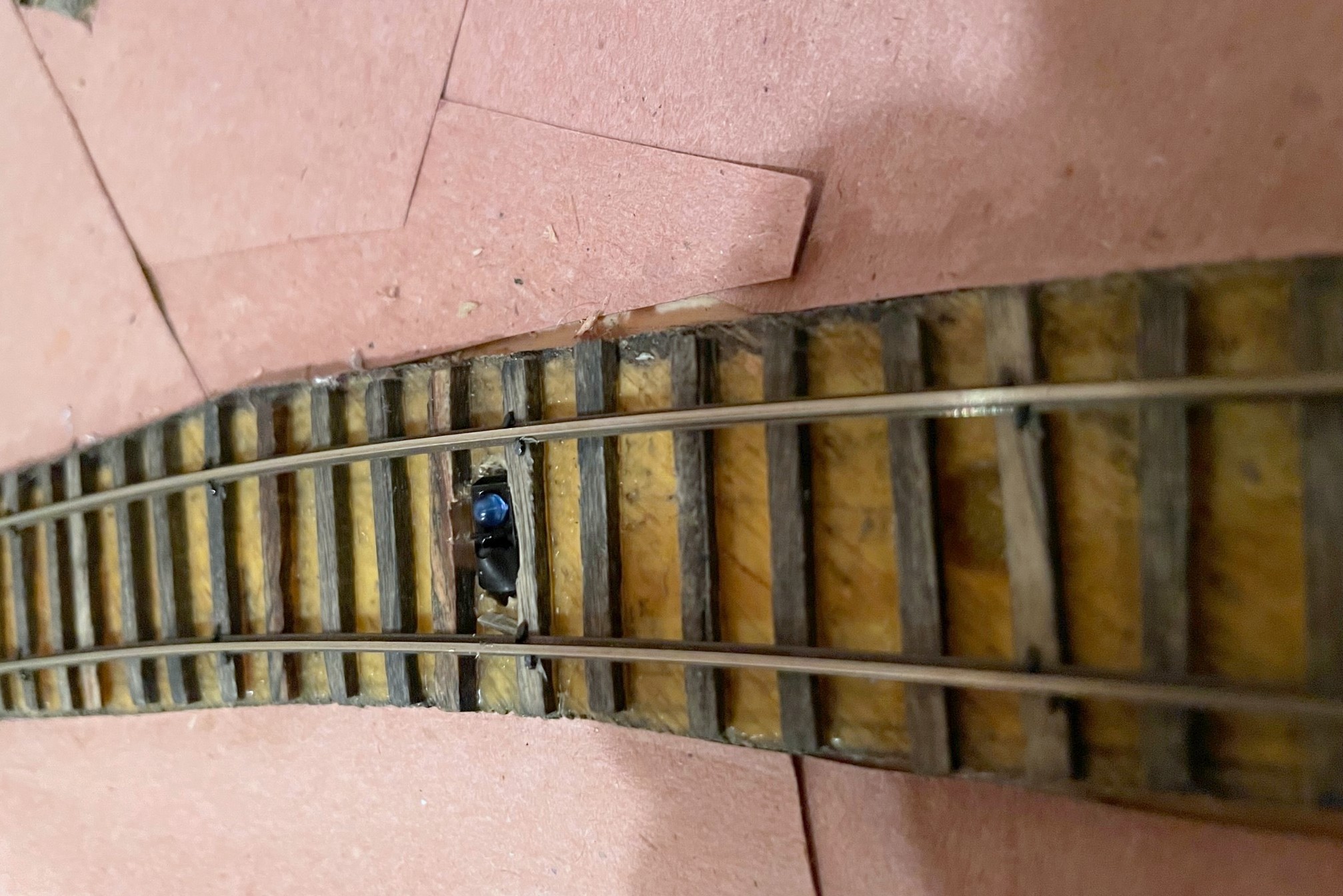
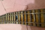
I installed the IR sensors between the rails and ties as the company indicates in the pictures. When anything passes over it within a couple inches, the IR sensor is triggered. There is no documentation on how the sensor works, but it has two elements, a blue dome and a black dome. I can only speculate that it transmits IR from one dome and receives reflected IR in the other dome. When I hooked everything up, it worked great… with two IR sensors plugged into the two separate sensor inputs on the master board. When I tried to use all four IR sensors, it would trigger the circuit no matter what I did even if nothing was present. I noticed some sensors were more sensitive than others, so I experimented with different placements and combos and even the positioning of the elements within the sensor. Unfortunately, I destroyed one of my sensors in the process, but thankfully they’re inexpensive, and I found the WeHonest customer service to be very responsive and helpful!
Here’s an IR sensor with a portion of the black dome covered in electrical tape to decrease its sensitivity
When my replacement sensors arrived, they did the exact same thing as before. Two sensors worked fine, four sensors triggered the circuit even with nothing present. I really liked the overall operation of these circuits, so I kept experimenting to see what might work. I speculated that the circuit detects based on a threshold of received IR energy–with one sensor, the ambient IR was low enough to stay below the threshold, but with two sensors, the ambient IR increased above the threshold to make it appear a train was present. I found that if I covered a portion of the black domed element on some of the IR sensors, it would keep the circuit from triggering but would still trigger if a train passed. After playing around, I found covering about 60% of the black element of all IR sensors with a small piece of electrical tape made everything work as intended.
Now that I’ve worked out the kinks, I’m very happy with the crossing! I’m able to control the sensor sensitivity via the electrical tape, I can control the flash rate of the LEDs via a dial on the flasher circuit, I can select the bell sound from one of several good options on the sound effect circuit, and all of this works automatically with no actions needed from the crew. I have two more flashing grade crossings to go on the upper level, and I’m satisfied enough that I’ve already ordered the parts to replicate this installation on those crossings.
Wiring diagram showing the connections needed between the three circuit boards, signals, and sensors
I mounted all three circuits and the speaker on a single piece of masonite to declutter and protect the wires
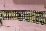
I mounted one IR sensor between routes on a turnout because either route requires the crossing signals to activate
Here’s an IR sensor with a portion of the black dome covered in electrical tape to decrease its sensitivity
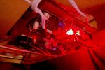
The circuits installed under the layout
The CV Local led by L&N RS3 100 crosses Bonny Blue Road with its newly installed crossing flashers
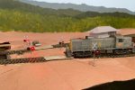
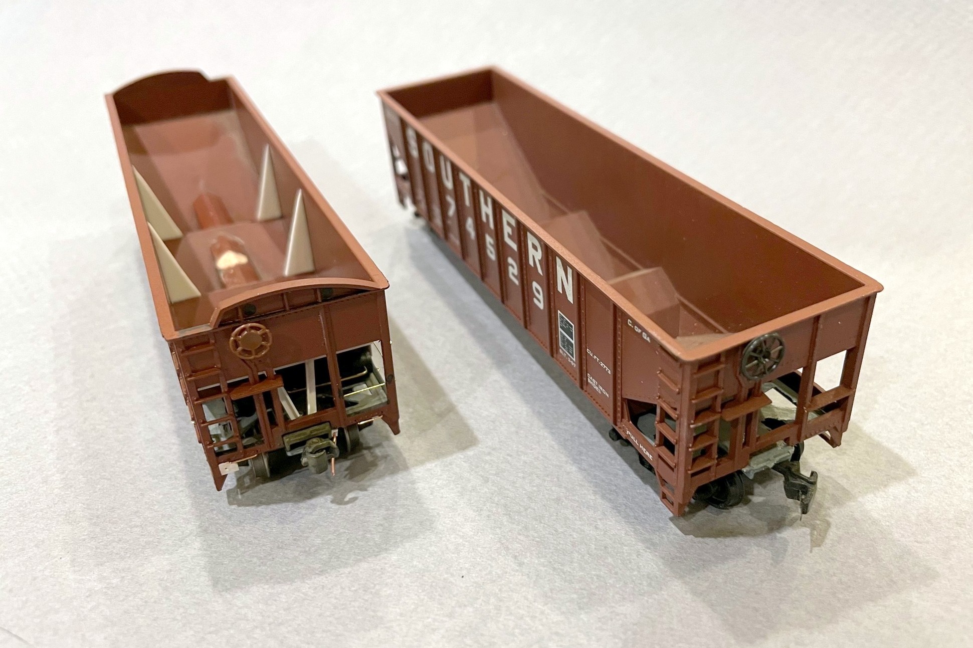
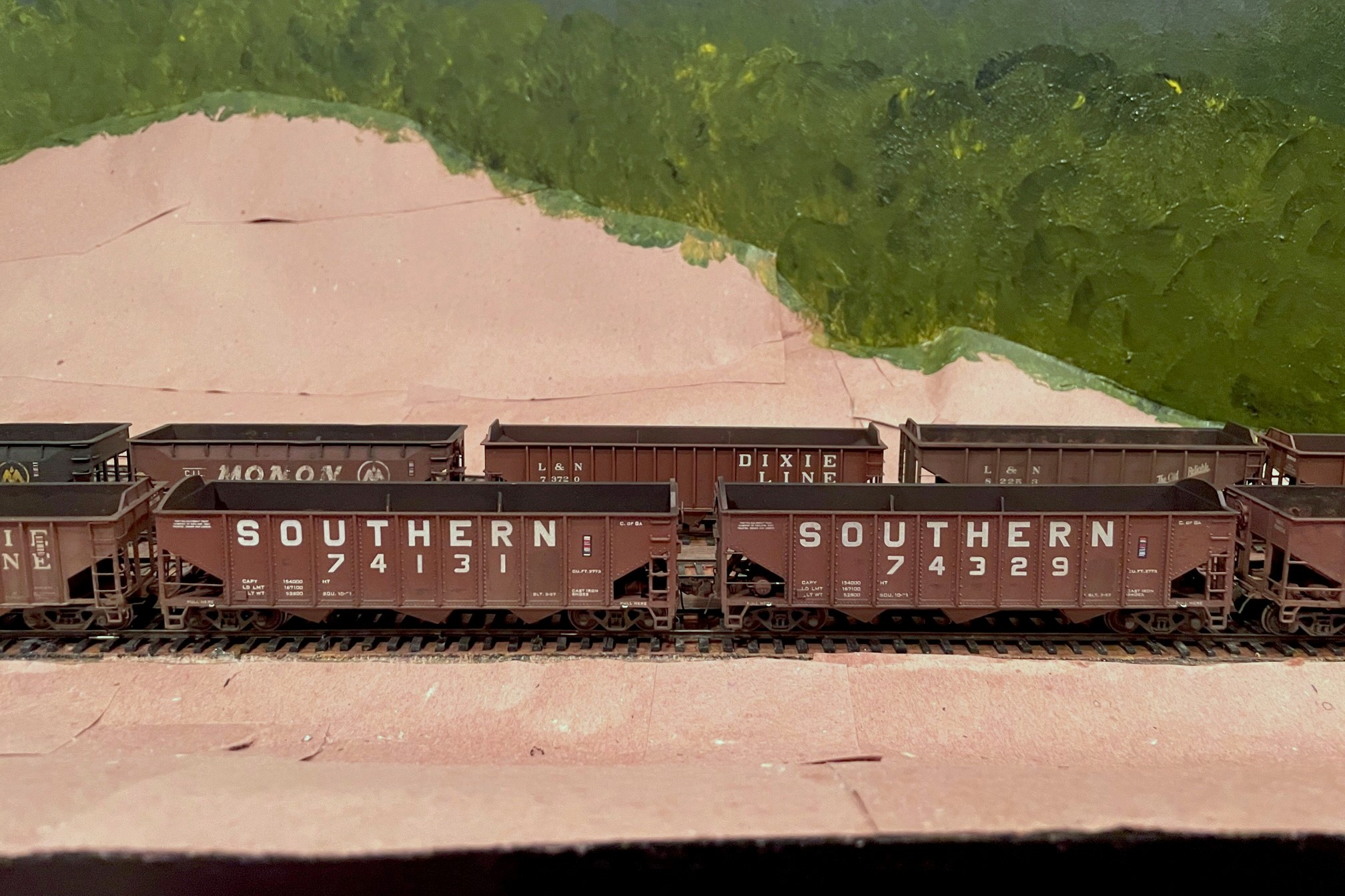
Side-by-side of an MDC car (left) and Atlas car (right) showing the slight length difference
In the last post, I mentioned some of the work that went into creating an ex-Central of Georgia 70T rib-side hopper from an old MDC Roundhouse kit. Atlas makes a much more crisp and better operating out-of-the-box car in its Trainman 9-panel, 70T hopper that is a good stand-in for this car, but it’s about 2 scale feet too long. The Atlas kit, however, is a great model for the Southern’s mainstay fleet of 70T hoppers in the 70300-73749 and 281000-281299 series which far outnumbered the ex-CofGa cars in the 74100-74584 series–all you have to do is remove the heap shields and renumber them. The MDC Roundhouse kit can be picked up in Southern paint pretty cheaply. It’s a far WORSE model both dimensionally and detail-wise to match the Southern’s main fleet of 70T cars, but its overall dimensions are closer to the ex-CofGa cars. However, it requires a ton of work to make the car presentable in a string of more recently produced and more detailed cars. So, is it worth the work? Spoiler alert: it’s not worth it unless you’re just a crazy hopper person like me who notices the subtle length difference between these different series of cars in a long string of hoppers.
Ok, if you’re still reading, here’s a little more on what it takes to model one of the ex-CofGa cars using an MDC Roundhouse kit or one of the slightly improved Athearn versions. First, what’s wrong with the model out of the box? These molds are at least 40 years old, so the detail is sub-par–the rivets are clunky, the grabs are thickly molded, the brake platform and brake wheel housing is grossly under-modeled, the brake wheel is horrendous, and it’s just missing some details like the long grabs on the left ends of the car and bracing inside the car. Also, the bottom sills and corner posts are super thick at the ends. The interiors have an ugly scar right in the middle where the injection molding was done. The most egregious issue is also the most likely to escape notice (so I didn’t bother fixing it): the middle hopper bay is reversed with respect to the brake end. The lettering is not up to today’s standards but acceptable for a car that will be weathered, but there is no lettering on the ends of the MDC cars. The car also comes with arched heap shields that can be added, but they’re a little too short to look right, something that I initially ignored but eventually remedied by replacing them with parts off an Atlas car. It’s also missing details that were on the CofGa cars like slope sheet bracing on the ends.
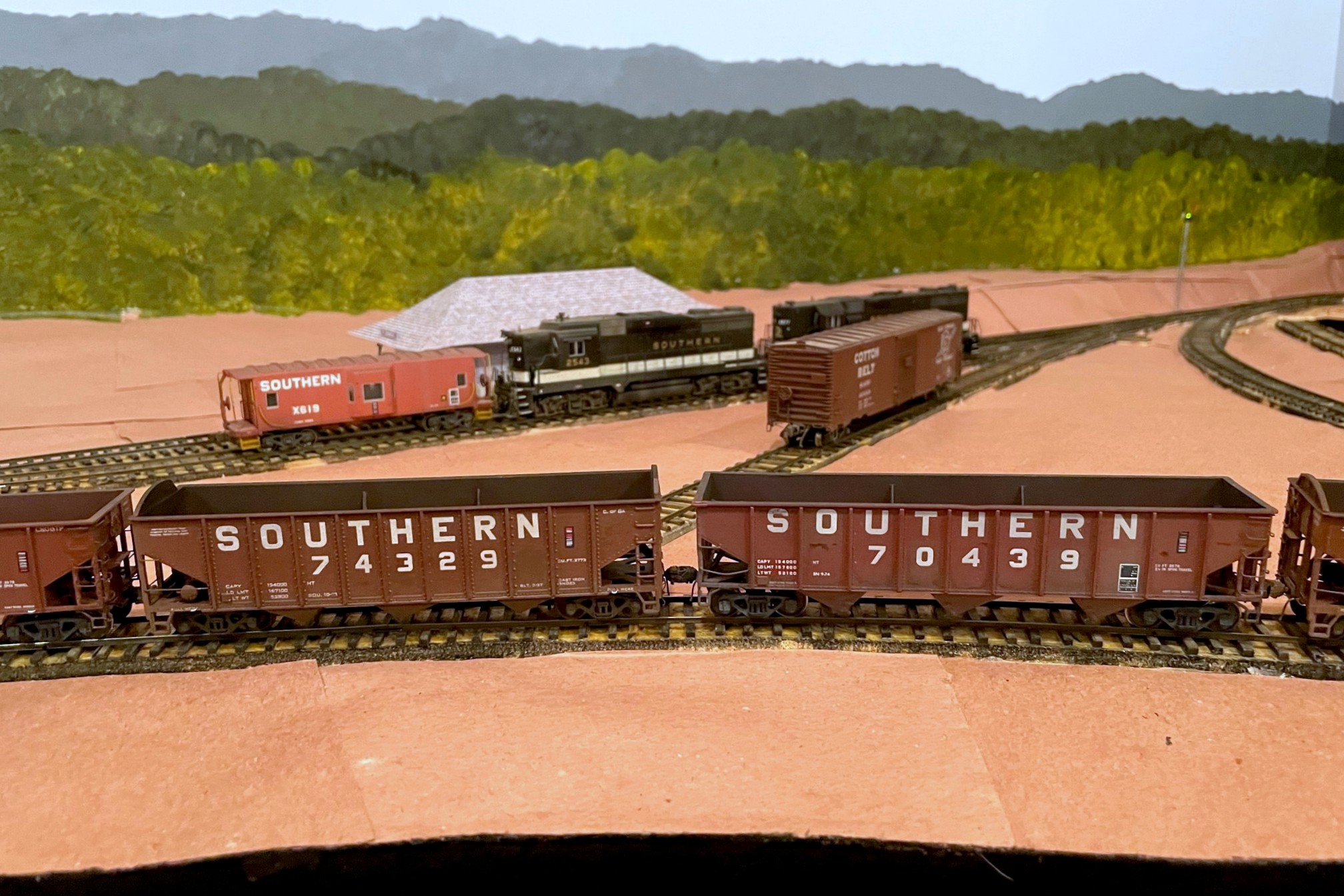
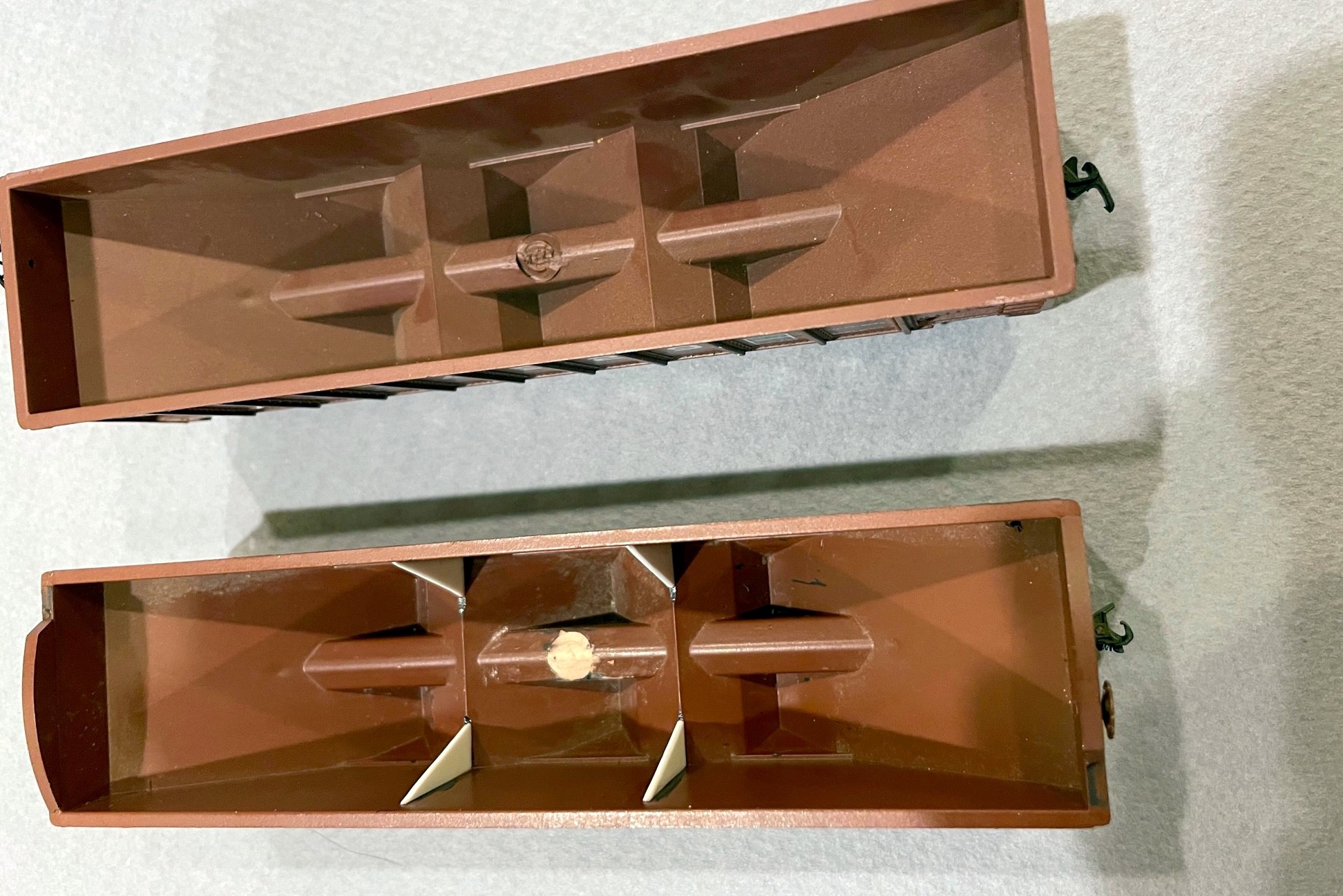
Detail differences between the original model (right) and the modified model–note the difference in the side sill width
I remedied most of these issues with an X-Acto blade. I started by removing the angles between the bottom sills and the side panels. Next I worked on the side/bottom sills and carved away excess material from the top and bottom with a No 11 X-Acto blade (leaving essentially just enough for the “PULL HERE” lettering). This was done to both the ends of the sides and the ends. I also removed the excess material from the left-side corner posts with a blade (I left the ladder side alone) and cleaned up the excess plastic in the steps. I narrowed down the ladder grabs with the X-Acto blade using repeated small cuts on the back side and alternating between top and bottom until the grabs were essentially round-ish instead of rectangular. I also used a chisel blade to remove the awkward rib down the center of the underside of the slope sheets. Finally, I removed the molded-on grabs from the lower ends adjacent to the couplers.
Details added include tack boards, grab wires, tow rings, cut bars, and train line
Next came the added styrene bits. I added some flat bits for the tack boards and the panels where the coupler cut bar would attach. Some large triangles (using the Atlas cars as a model) became the interior bracing. The most complex part was the slope-sheet bracing under the ends. I made these from three pieces of L-girder styrene and just dimensioned and cut them to resemble photos. I also replaced the brake wheels with more detailed Miner wheels from the parts bin (one Kadee and another whose origin is lost). I added wire grabs adjacent to the couplers, and added custom-bent long grabs on the left ends made from .012″ brass wire and tow loops made by bending .012″ brass wire around a thumbtack (I bend them into a “J” shape and just drill one hole). I bent coupler cut bars and eye bolts from .012″ brass wire using a little jig I made. I also added a couple pieces of brake-gear piping between the reservoir and triple valve bent from .020″ brass wire. The train line is a piece of copper wire from an old ethernet cable sandwiched between two pieces of L-shaped styrene. The final details included Kadee No 5 couplers, Intermountain metal 33″ semi-scale wheels (faces, backs and axles painted black), and arched heap shields salvaged from Atlas models (the in-progress photos here show the MDC arches which I replaced before weathering). Some careful carving and putty fixed the ugly scar on the center sill inside the car.
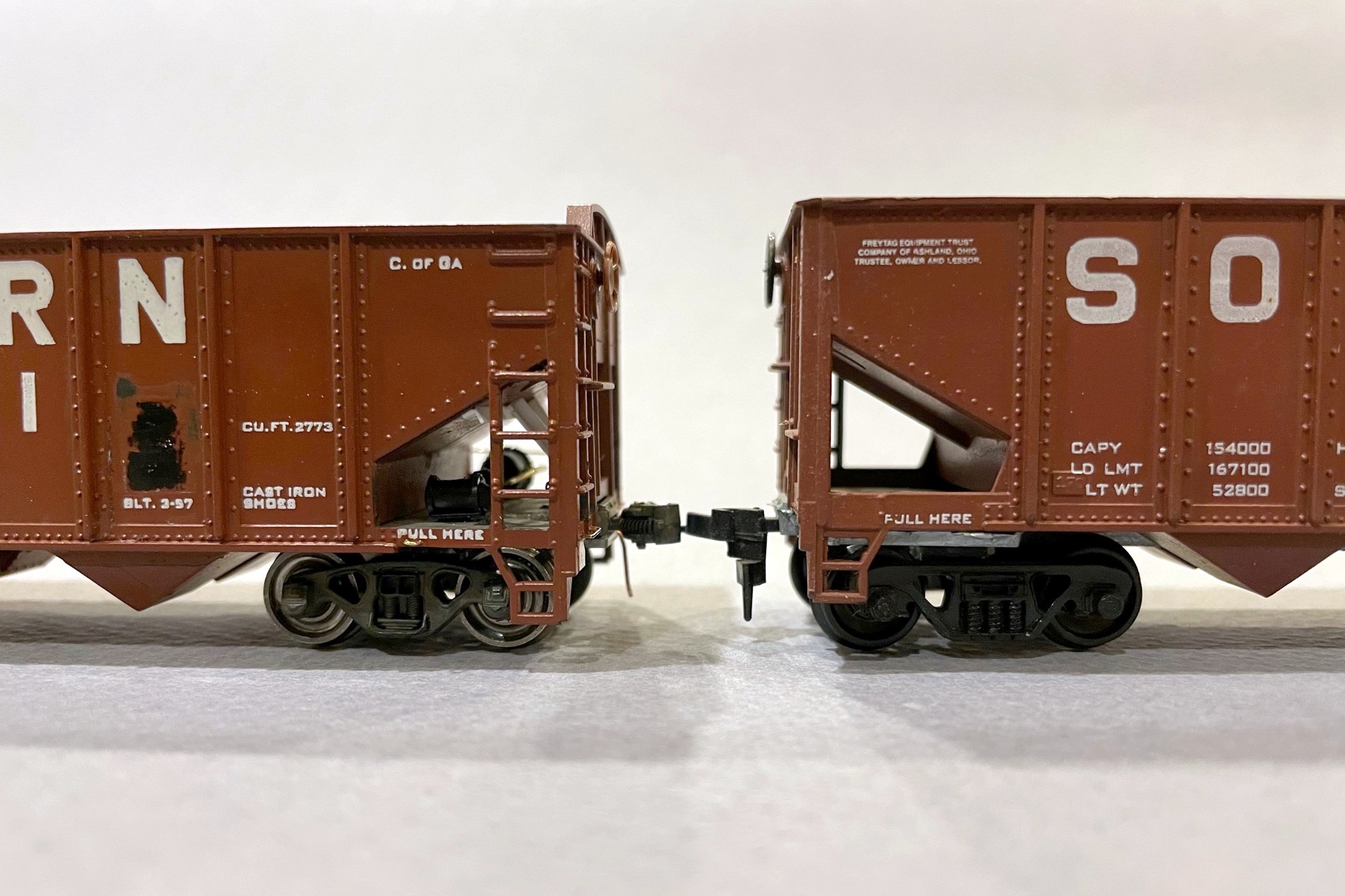
Detail differences on the ends
I wanted to renumber the cars and detail them for the early ’70s, so I removed a couple of the numbers and the black-and-white lube stencils the best I could by scraping them off with the back of an X-Acto chisel blade. I custom-mixed some paint to match the body and covered all the new details and scraped sides. I added the new numbers, ACI labels, and end reporting marks using a combination of Microscale, Herald King, and K4 decals. Now they were ready for weathering!
Interior detail including braces and covering up the injection mold scar
For weathering, I started with some drybrushing of dark rust spots in a few places on the sides. Next I airbrushed them moderately using a combination of flat black and dark tan airbrushing and washes. Since these are old cars that have been repainted, I went a little heavier than usual with the black on the interiors. I hit them with a wash of flat black paint and water, letting it sit for a minute and then wiping it off vertically to produce some rain streaking and shadows on the details. I used a wash of light orange rust and water on the interior and then added some drybrushed rust spots inside.
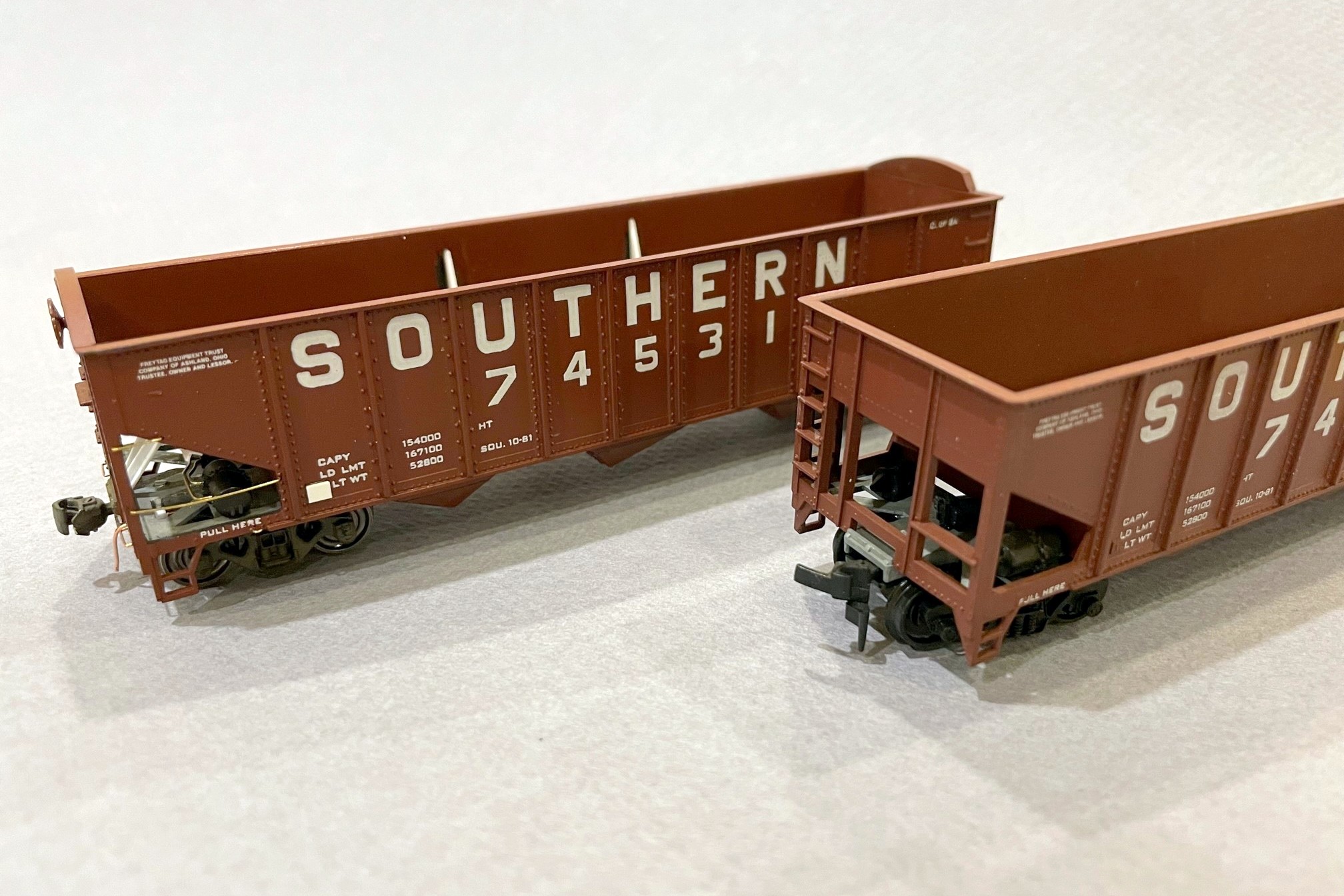
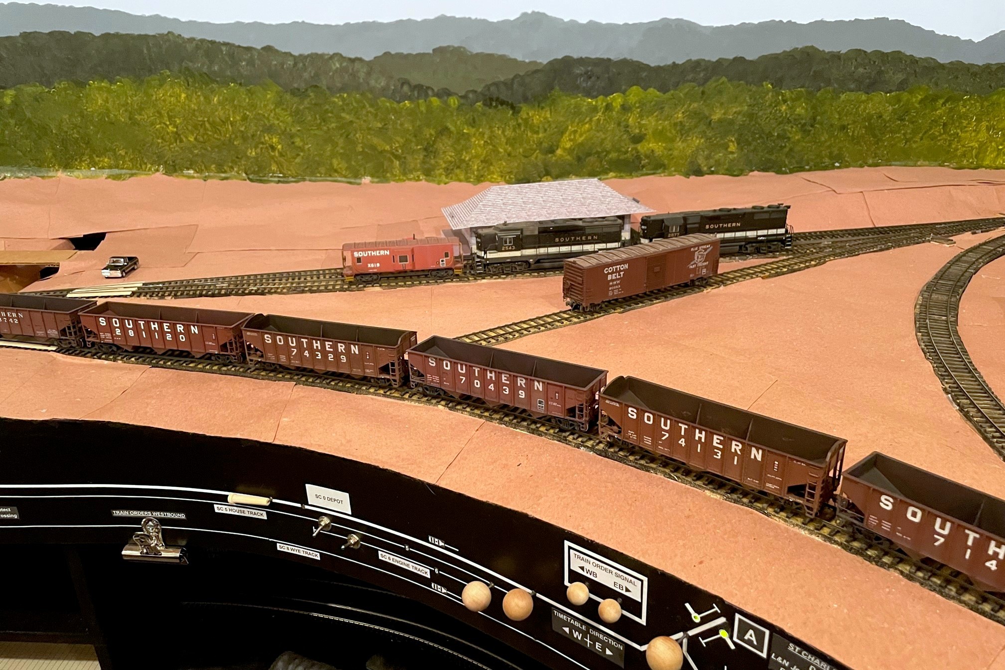
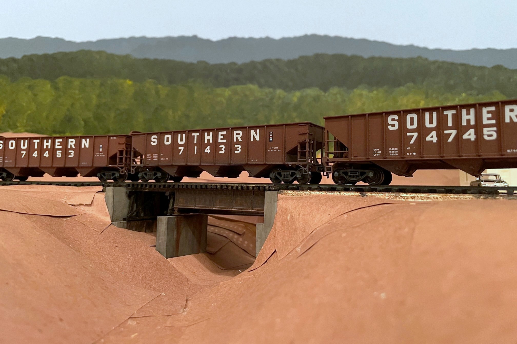
String of Atlas and MDC cars mixed in–the differences are subtle but noticeable
In all, these cars took probably 4x as long to detail and make layout-worthy as the Atlas Trainman cars. Now that they’re complete, I do like seeing the more stocky look of these CofGa cars mixed into a long string of Southern-heritage 70T cars. So much so that I’ll probably eventually go back and take all the heap shields off my Atlas cars and renumber them into non-CofGa series. Thankfully I’ve only completed 3 of these Atlas models, so it’s not a huge sacrifice. So, if you’re a hopper nut like me and nerd out on seeing the subtle differences between car series, then knock yourself out on a project like this! If you’re not a hopper nut, I recommend sticking to the Atlas models and saving yourself a lot of trouble.
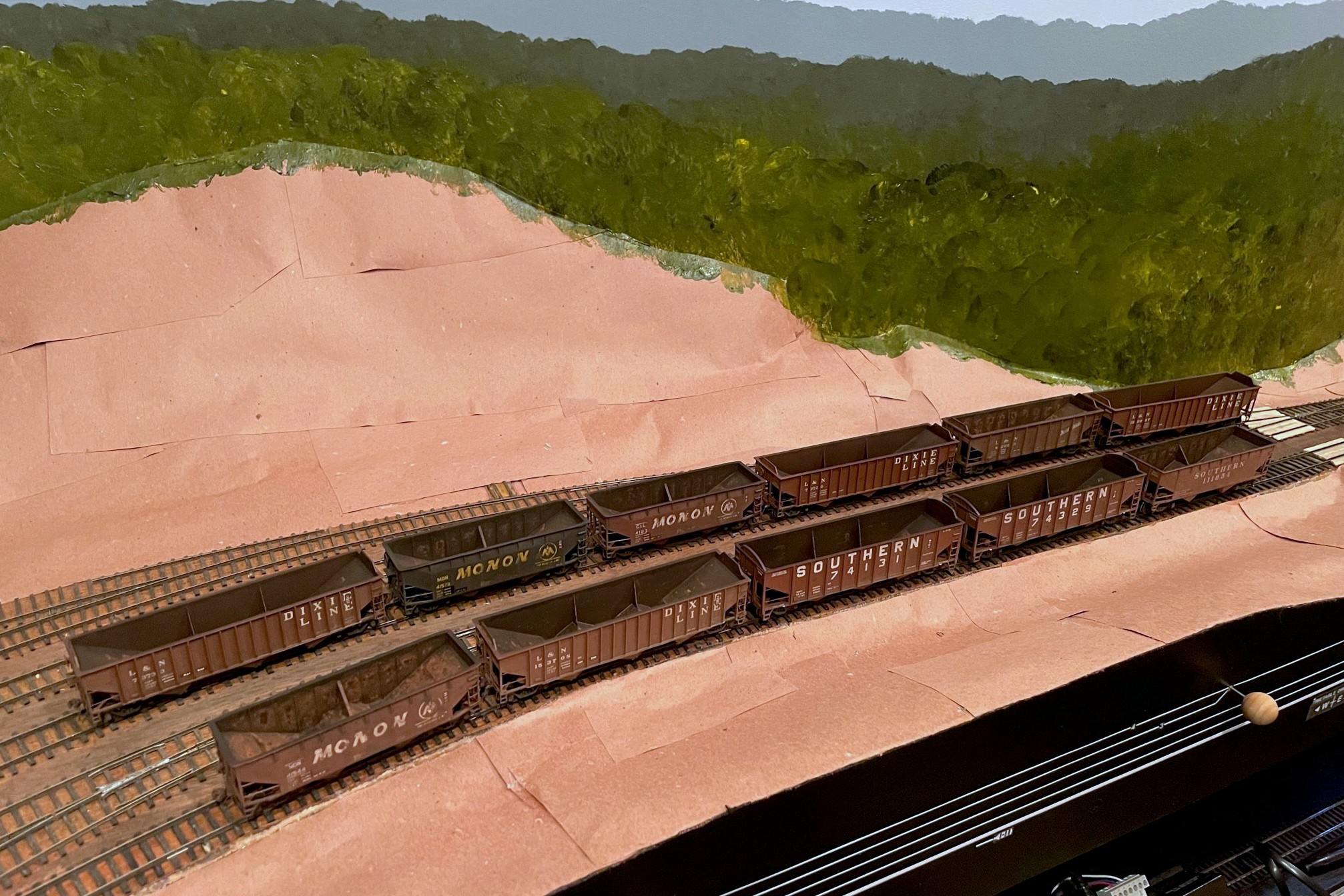
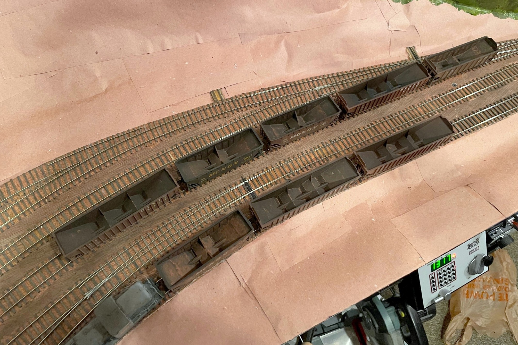
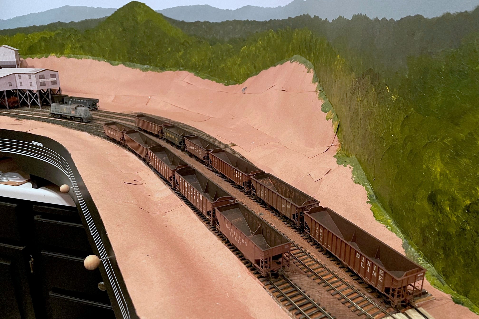
The hopper class of April 23 consists of 11 hoppers, mainly L&N and heritage cars
It’s time to introduce another “class” of hoppers graduating from the workbench to the layout. Looking back I see the last class of hoppers graduated in April of ’22, so I guess I’m averaging about a dozen hoppers a year… got a ways to go! This class was fun because most of the cars are for the L&N trains on the layout. Previous to this, most of my L&N cars were of mid-’70s paint and markings, so I focused on some cars to represent the mid-’60s to early ’70s including four PS3 70T cars, a PS3 50T car, and three ex-Monon two-bays (ok, I don’t need 3 Monon hoppers, but they came as a set, and I got them for cheap so…). The three remaining cars represent Southern prototypes including two ex-Central of Georgia 70T cars and an old 50T offset in red with Roman lettering.
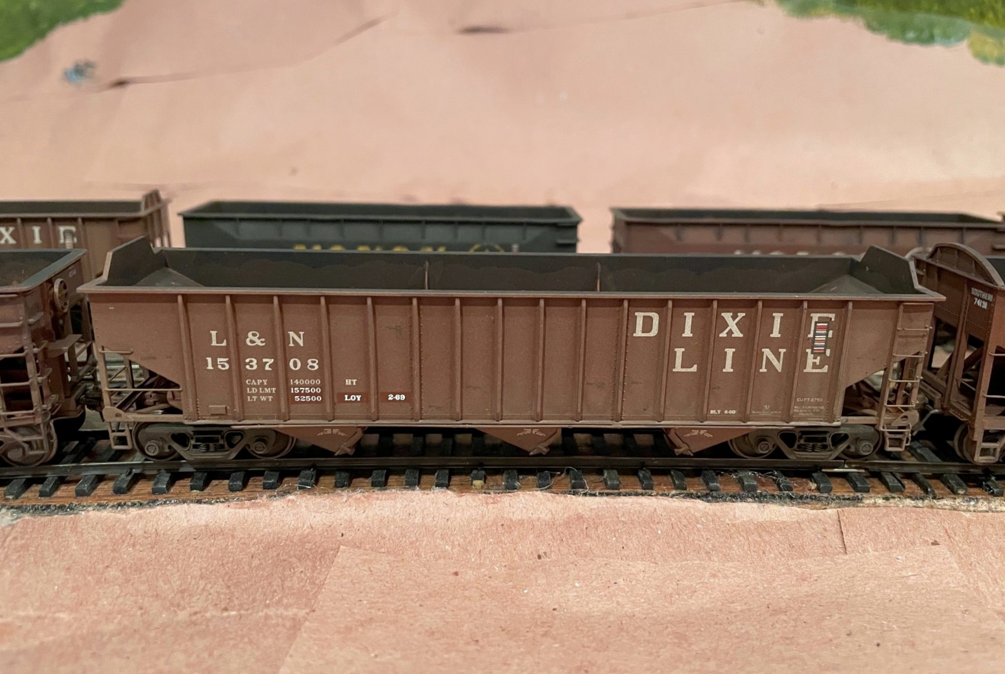
This Tangent PS3 2750 hopper received a new number, corner tow loops and roller bearing trucks to represent a later series of cars
The easiest cars of the bunch were the 70T PS3s which are all factory-painted Tangent cars with excellent detail. The four cars all came lettered in the 73000 series, and after looking through pictures, I decided they’d also be good to represent the 150000 and 153000 class cars that were also delivered in the “DIXIE LINE” paint scheme. For hopper 152067, it was as simple as changing the number and build dates. I scraped off the old lettering using an X-Acto chisel blade–it leaves a little shiny spot, but this is easy to disguise with weathering. Hopper 153708 was a little more involved because this class came with the later style tow loops at the lower corners of the car and roller bearing trucks. I snipped off the modeled loops, cut new corner tow loops from .015″ styrene, glued them on and painted them. A set of Bowser roller bearing trucks and metal wheels fit well and kept the car at the proper height.
This L&N PS3 is a factory painted Walthers Trainline kit that’s received new ladders and other details
The 50T PS3 is a factory-painted Walthers Trainline kit which is an updated version of a VERY old model kit that’s been around since probably the 60s and has pretty clunky detail. I remedied the worst of the detail issues by cutting off the ladders and replacing them with DA ladders and added new scratchbuilt heap shields. A new Kadee brake wheel and some new wire details like brake gear piping, grabs, cut bars and train line hose finished the detailing.
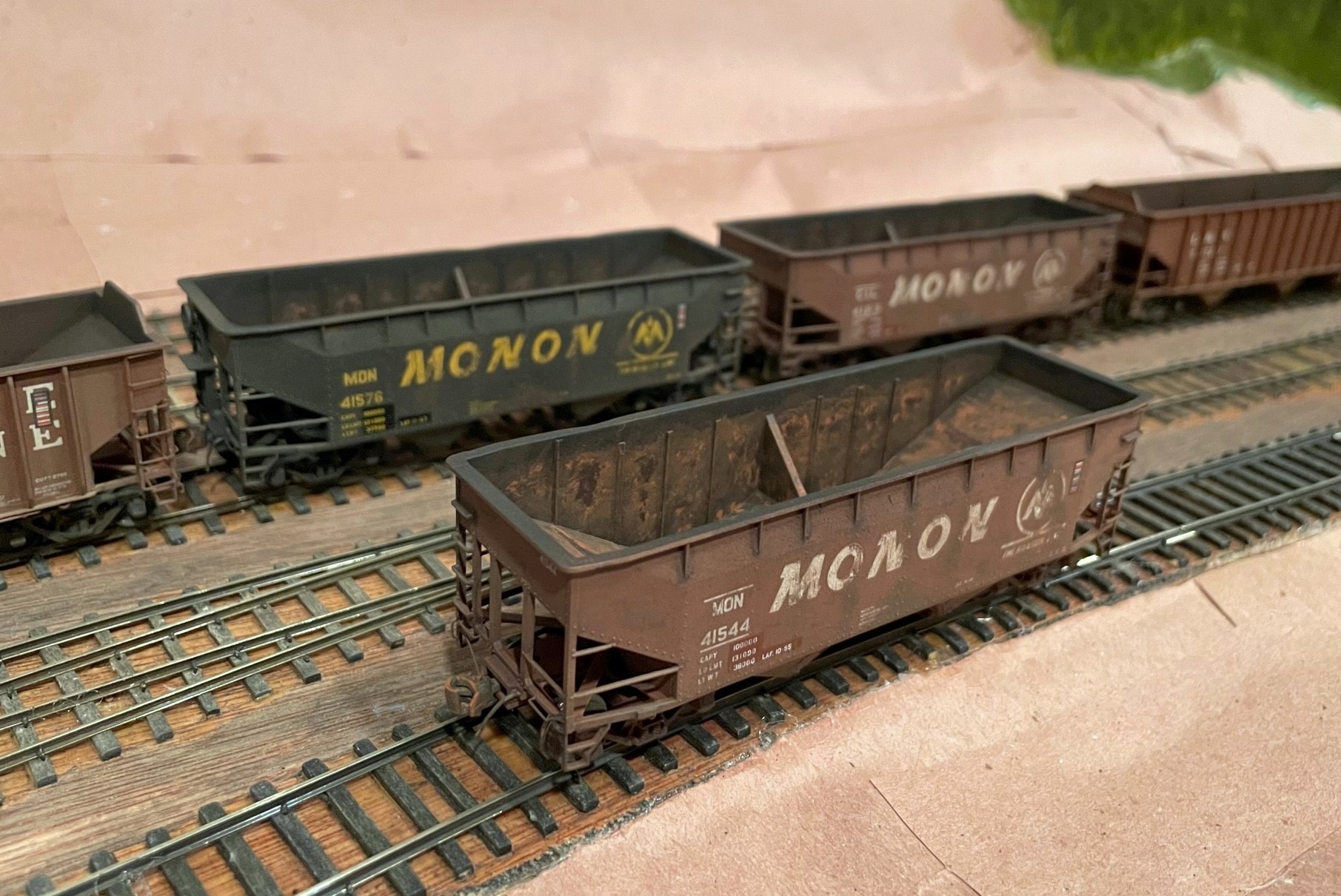
These three hoppers came in a single box from Atlas–they’ve had their details enhanced and have been extensively weathered but are otherwise stock
The Monon 50T hoppers are pretty much stock, factory painted Atlas hoppers. I used my favorite “grab narrowing” trick where I carefully cut away the back of the ladder grab irons with a sharp No 11 X-Acto blade. This makes the detail look much finer from any distance and is easier and quicker, in my opinion, than completely replacing the grabs with wire. I did add some wire grabs on the lower ends along with some cut levers and train line hoses.
Southern 50T hopper in Roman scheme weathered as if it’s seen a few miles
The Southern 50T offset hopper is a factory-painted Athearn model from a set of six (more of these to do). The roman lettering was common in the early ’60s and was almost entirely phased out by 1970. I wanted to model it in its last year or so of old paint. Detail-wise, it got the narrowed grab treatment, a new Kadee brake wheel, and a few wire details.
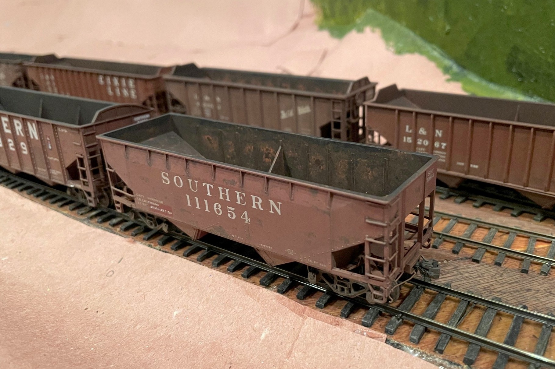
These two ex-Central of Georgia hoppers started as Roundhouse kits but are full of added and modified parts
The most work-intensive of the bunch were the two ex-CofGa 70T hoppers. These began as factory-painted Roundhouse kits (one used, one “new” but very old stock). Up to this point, I’ve been content to use the Atlas Trainman version of this car which is a pretty good stand-in. I also use the Atlas cars for my “primary” Southern 70T hopper fleet, and in reality, the Central of Georgia cars are 14″ shorter in length (40’6″) than the Southern’s big 70300-73749 class of cars (41’8″)… crazy me, I thought “wouldn’t it be cool to have the ex-CofGa hopper be noticeably shorter in a lineup?” Let’s just say these cars need a LOT of work to bring them up to modern standards and to correct the most egregiously noticeable detail faults and missing details. Lots of styrene, cuts, and extra details later, these cars emerged. Perhaps I’ll do a whole write-up on them [see the full write-up here], but they do, indeed, look cool and distinct in a lineup of Southern 70T cars… was it worth it? Only to a hopper freak like me.
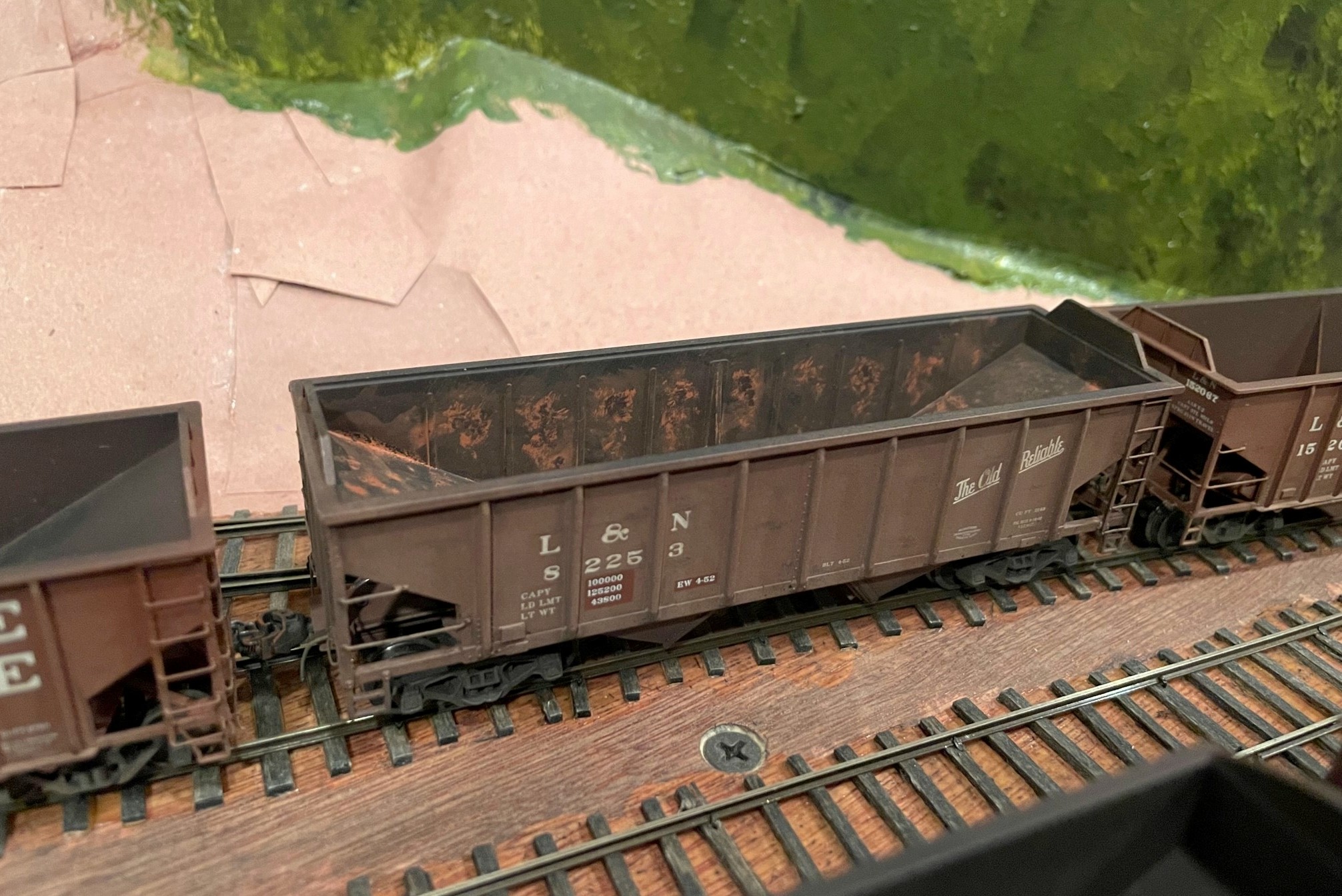
I spent more time than normal weathering the interiors of these hoppers using a combination of airbrush, washes, and dry brushing
Most of these models represent cars that were already 10-25 years old when I’m modeling them, so they got some pretty heavy weathering. I did some dry brushing of rust spots on the exterior. The Monon cars got some car-colored dry brushing to fade portions of the big “MONON” using pictures as a guide. On several of the cars, I masked off portions of the data (LT WT and LD LMT) and shop markings with rectangles of tape–when peeled off after the airbrushing, it looks like re-stenciled data which is appropriate for cars this age. I airbrushed them all with a light spray of flat tan to fade them a little and add some dirt, especially around the trucks and bays. I also airbrushed some flat black into the interiors–the older the car being represented, the more black it got. Next I used a wash of black with a little tan on the outside to darken the seams and corners and dull things down. On the inside, I used a wash of Vallejo “orange rust” and water and dabbed it on heavily with a big brush, letting it dry in splotches and in the corners (some got a couple coats). For the oldest cars, I drybrushed the interior with orange rust, particularly along edges and panel lines. Finally, I put dabs of Vallejo “dark rust” into the centers of the orange spots to make it look like an old but growing rust spot with fresh orange rust along the outsides and dark rust in the middle.
Overall, I’m pretty happy with the additions, and it’s fun to have a few “rust buckets” running around in the trains. Can’t wait to load ’em at the next ops session!
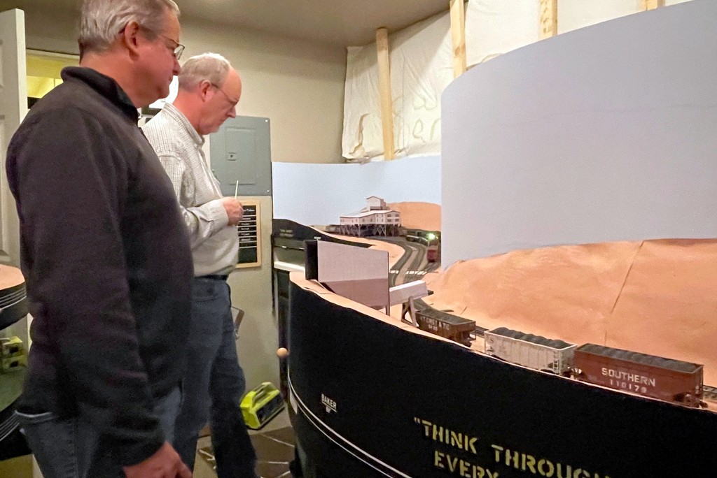
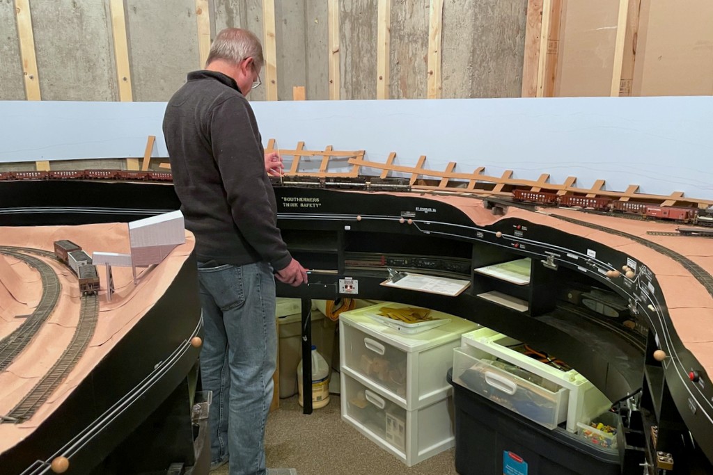
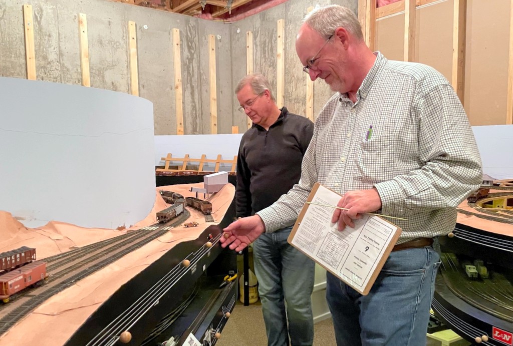
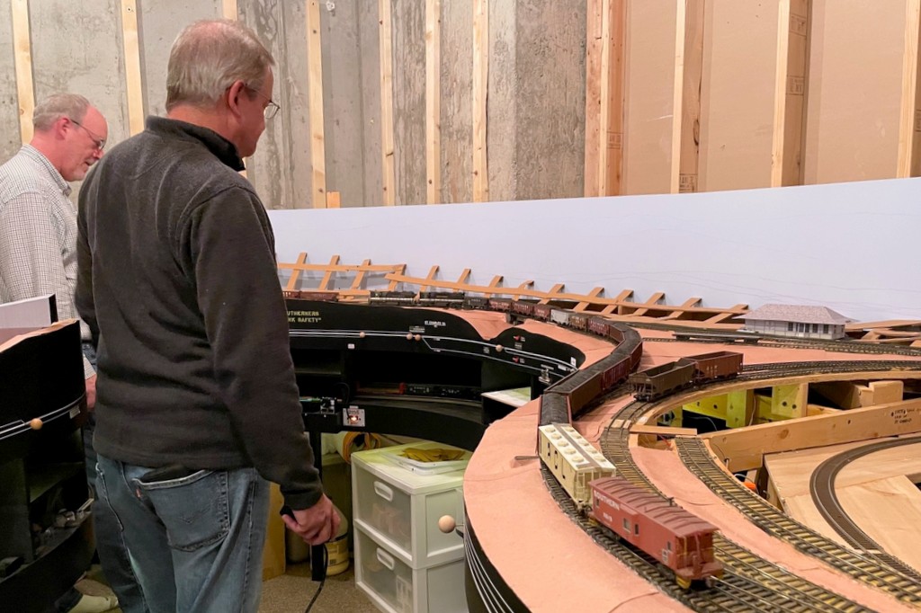
Rick directing the switching moves at Mayflower as conductor for the St Charles Switcher
Had a great small operating session with a new operator, Rick Trinkle. Rick is an O-scaler and serious BN modeler, so I tried to show him that the hills are greener in the HO scale Appalachians. We took our time and ran three trains over about 3 1/2 hours circa 1976. It was amazing how much more “in role” the layout seems with a few mountains painted on the backdrop and the basic hills down. The layout also cooperated more than usual with only a few slight hiccups… each time is an improvement.
Rick pointed out this cool view that is now possible with the backdrops complete… just a little foreground needed…
One new thing I added to operations was an “origin” column in the master switch list to go along with the “destination.” This allowed us to not only build a custom switch list with the cars in our outbound train, but it allowed us to search through the master switch list to identify the cars we should be picking up to make it a complete switch list. Going to stick with this!
There were some “firsts” in this session:
First operating session with any “green” on the layout
First use of an “origin” column in the master switch list
First use of a TCS Wow Sound decoder (a replacement for the burnt out LokSound in my L&N C420)–sounded amazing, especially shoving cuts of cars up the hill to Mayflower!
Learning points:
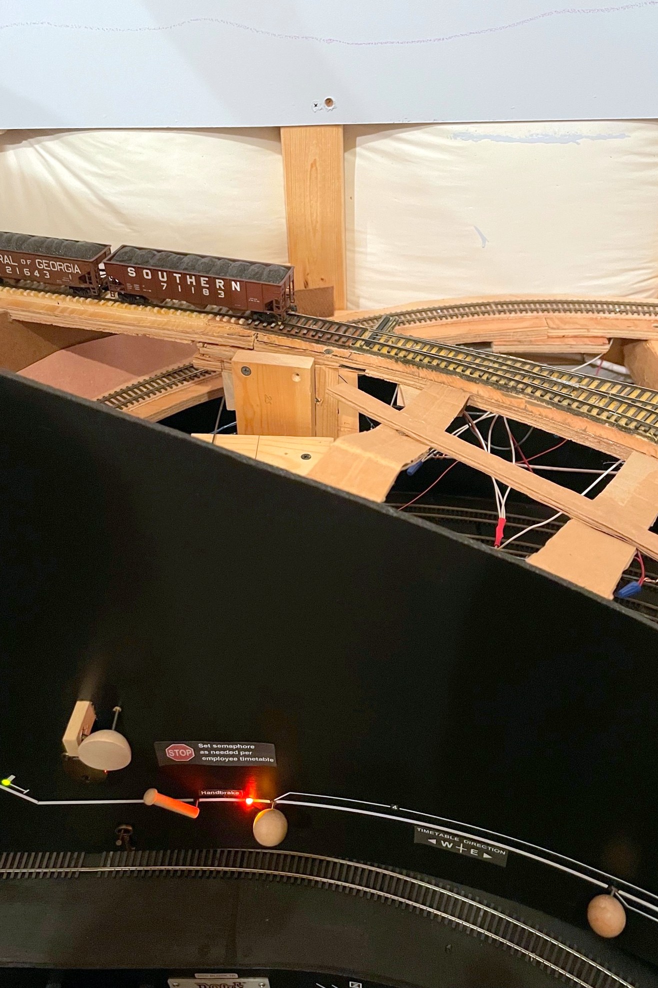
Gravity-assisted switching moves are useful and doable with the “handbrakes”–we used the brake above the yard twice to move the caboose from one track to another using gravity instead of a long run-around–saved a lot of time!
Still a couple derailments, both Tangent cars… very odd since these are the heaviest cars on my layout
Still need a couple more “handbrakes” in spots to keep cars from rolling when spotted–these can be the simpler static paint brush variety
Rick working the St Charles Local dropping empties at St Charles YardThe ever-dreaded back-up move shoving 25 empty cars into the yard at St Charles
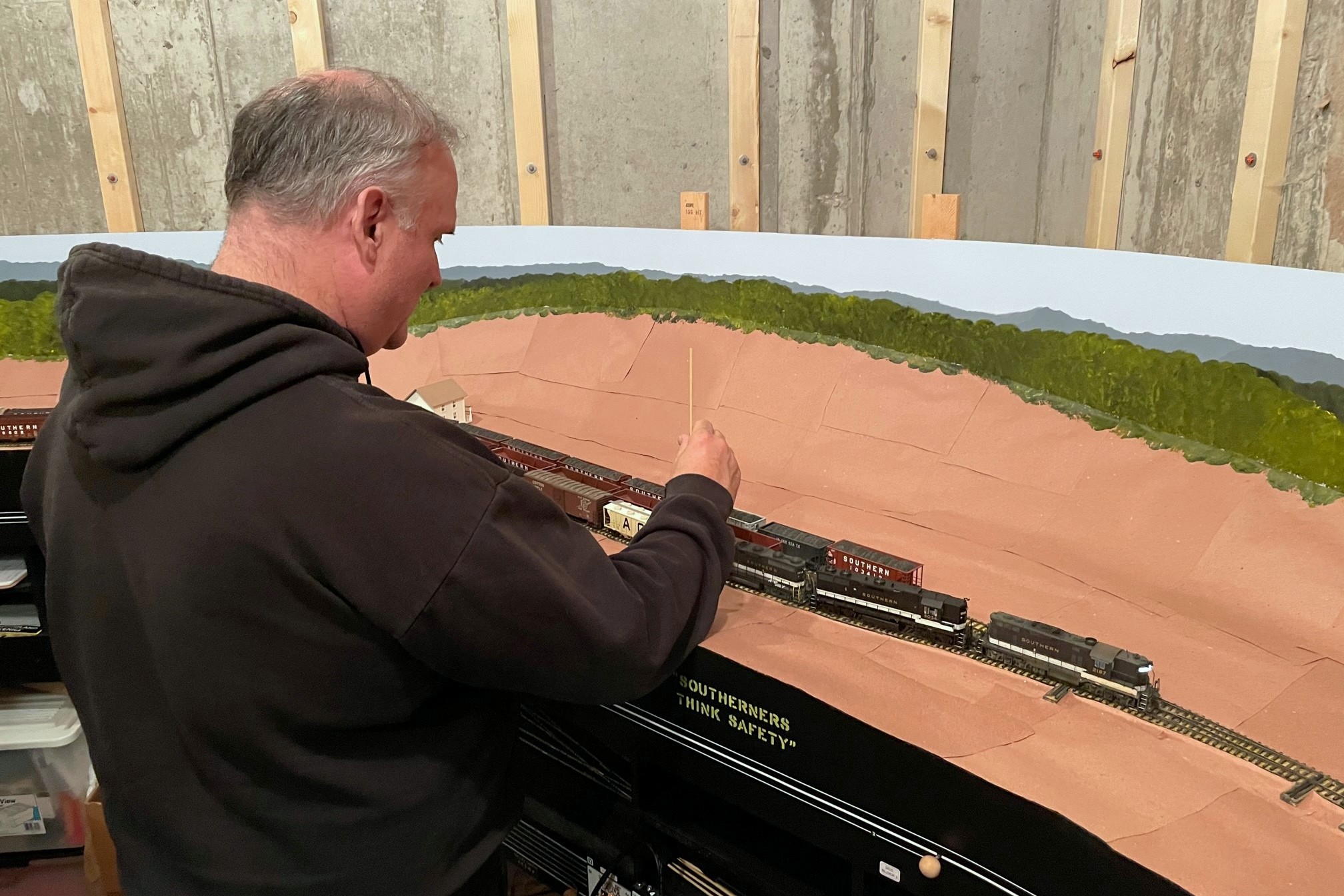
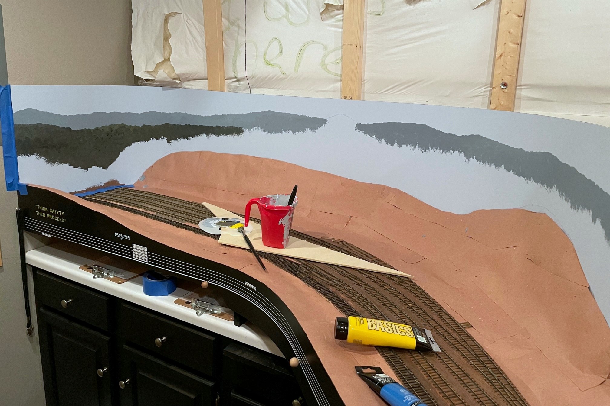
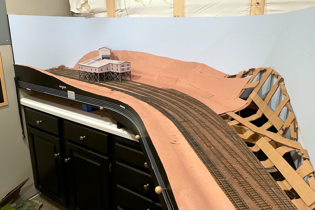
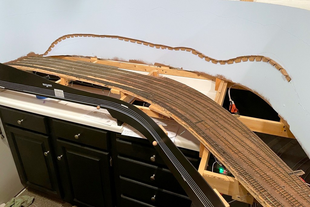
Here’s a look at last Saturday’s progress including finishing most of the lower level scenery base and painting the rest of the backdrop
I had a happy aligning of the stars on Saturday where my wife was gone for the day, I didn’t have any big “chores” to do, and I had just learned how to paint backdrops! All that combined into a day spent furiously trying to finish up the lower-level scenery forms so I could paint the rest of the lower-level backdrop. It was a good day, and I’m pretty happy with the results. I learned that the painting is my favorite part, roughing in the scenery with cardboard strips is my second favorite, and papering over the cardboard with section after section of red rosin paper is a distant third. Round 2 of backdrop painting went a little smoother than round 1 as I think I had a better grasp of the techniques, and the paint brushes seemed to work better on their second use. I liked the results of round 2 so much I went back and redid some sections of round 1.
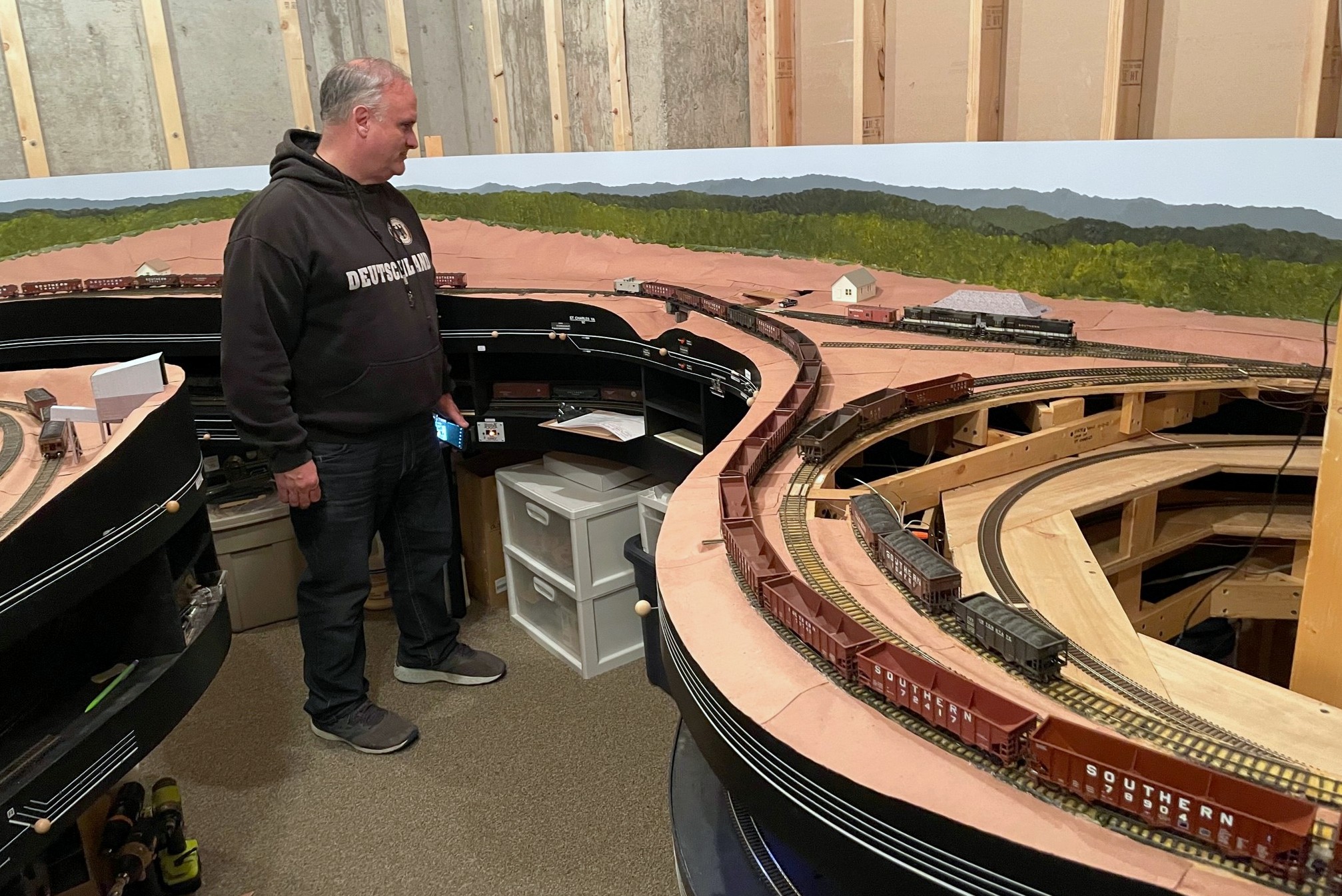
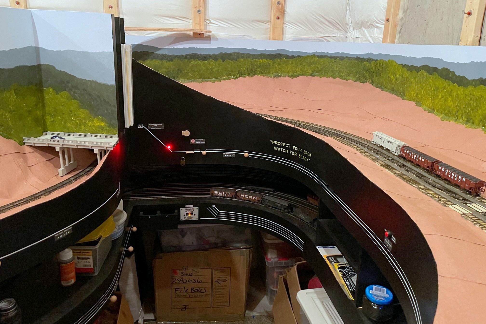
The St Charles Local traverses the wye with the newly painted backdrop. It will soon descend through the backdrop in the corner, a hole much tougher to spot now
The scenery covers over the hidden track along the back wall that joins St Charles and the Mayflower section, so I decided to do a test run… I can now verify that I can indeed – by twisting at odd angles, reaching into small gaps, and fishing it out the last couple feet with a long string of hoppers – free a stuck train from the most remote part of my hidden track! Lesson learned–when you use hot glue for scenery, it tends to leave a lot of strings hanging down, and go figure, locomotives don’t pick up electricity so well when their wheels are covered in bits of glue string! A little wheel cleaning and some extra sweeps of the hand through the area (again at odd angles via small gaps), and trains now traverse this area nicely.
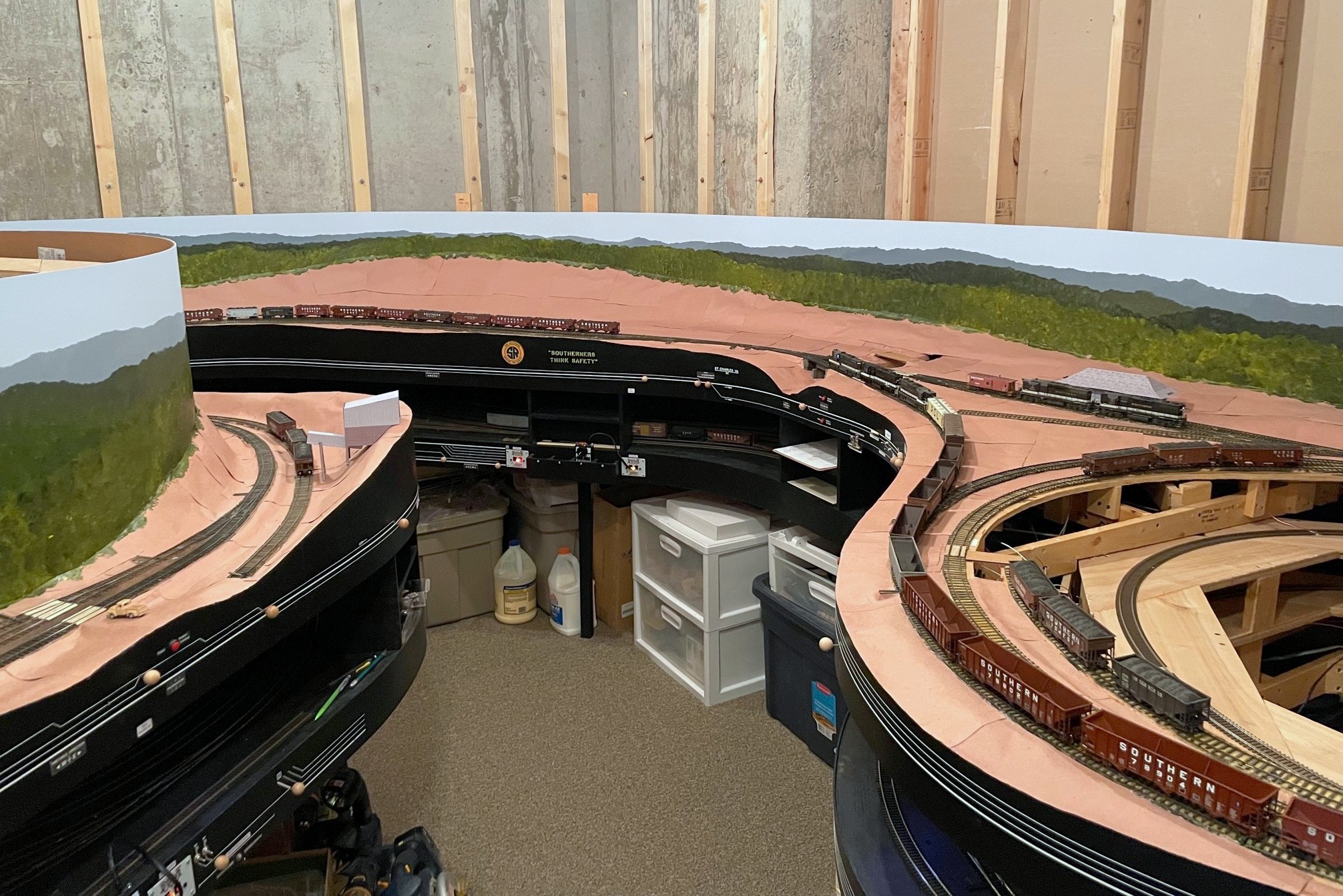
Where the two lower-level scenes transition–the backdrop on the right is lower than the left, hence less blue sky
I’ve only got one section left that still needs a backdrop and scenery forms, over the helix from staging. Painting the backdrop in the corner was the big barrier to adding this, so that will likely be the next step, and the LAST step before building upper-level benchwork… it’s getting pretty real.
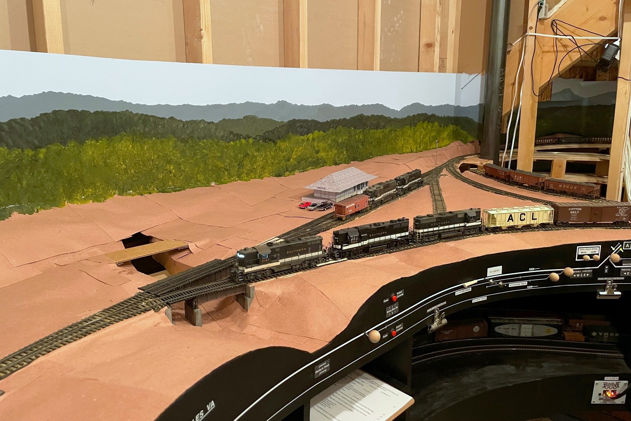
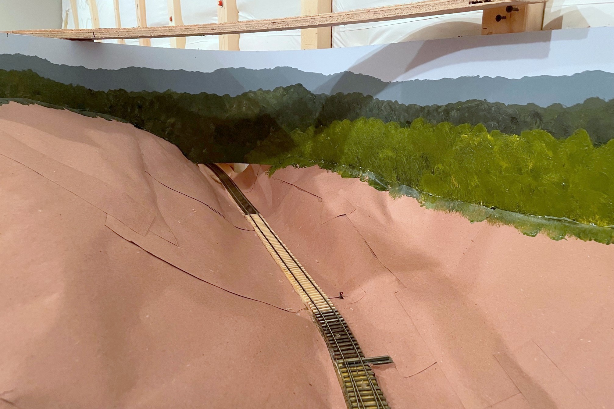
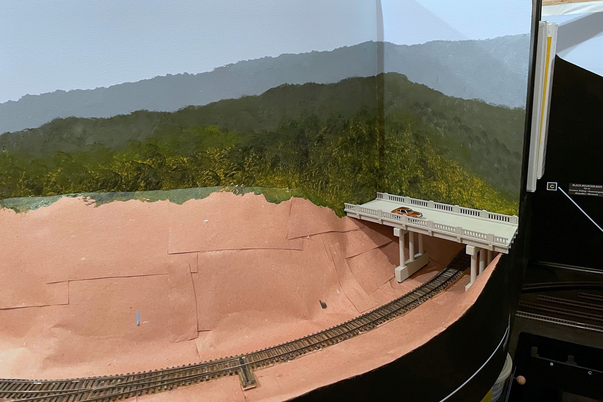
Here’s where trains will leave the lower level and enter the helix to the upper level–I think the backdrop painting along with a few trees will hide the transition well
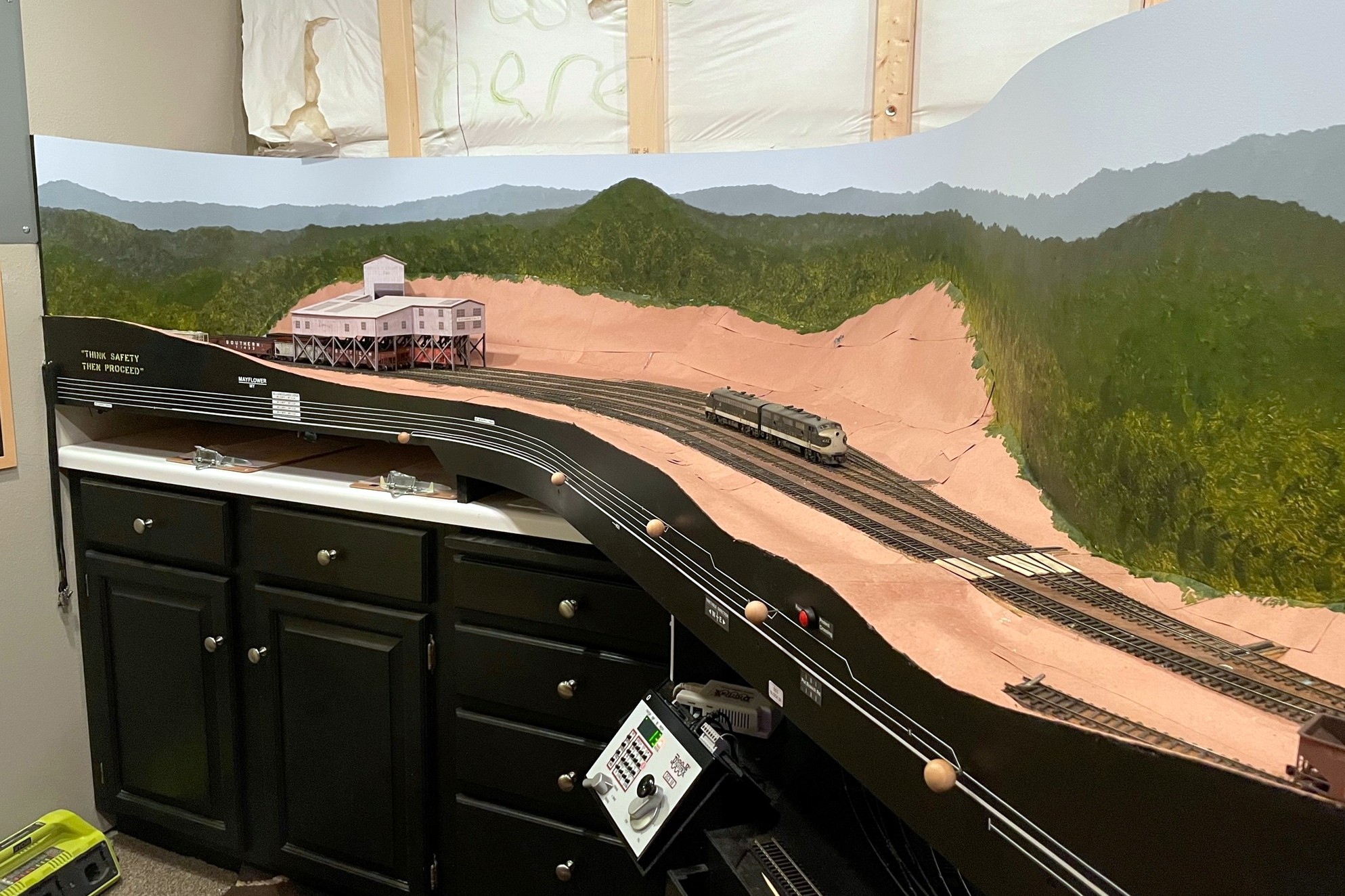
The finished scene showing the brighter foreground trees painted with yellow and mars black mix–what a difference the painted backdrop makes for the scene!
I collected art supplies to paint my backdrops many months ago, but like any project that intimidates me, they sat around in a drawer until I could get up the nerve to pull the trigger. I’ve done one painting my entire life about 30 years ago for an art class, so my experience level with this is just a hair above zero. I’d like to thank Jeff Kraker who sent me a link to a video series by Chris Lyon he followed on how to paint backdrops using a few basic acrylic colors and an impressionistic “blob” method. I learned a TON from this five-part series including the fact that you shouldn’t actually use green paint–how counter-intuitive is that? Having watched the series twice and armed with supplies, I finally jumped in! As you can see in the pictures, I’m no Michelangelo, but I’m happy with them for now, and I’m sure I’ll make some adjustments and touch-ups as I gain more experience.
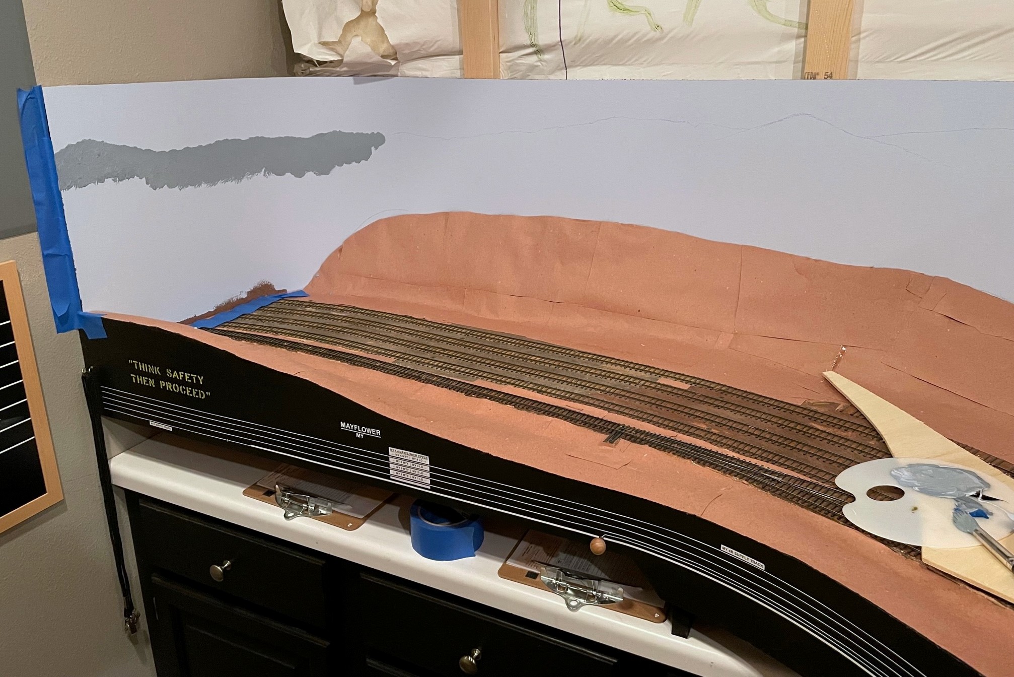
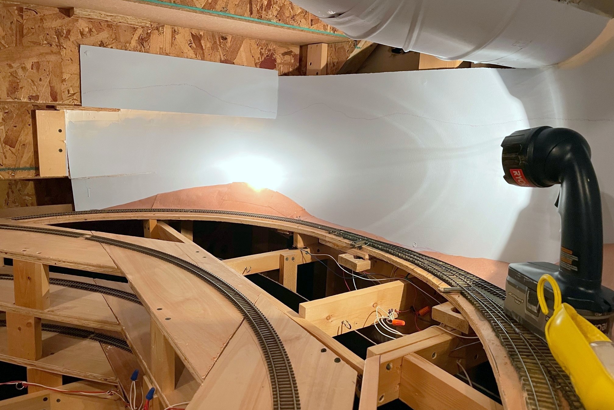
Step 1 is to outline the distant ridges in chalk, and step 2 is to paint the distant ridges a bluish gray
My first step is to outline the top of the distant ridges. I actually used a low angle view from Google Earth to do this, so the basic contours are actually what you’d see standing in the actual scene. Kid’s sidewalk chalk is a good medium for this as it can be easily erased with a wet wash cloth. Next I painted my distant ridges–this was something the series didn’t cover as all their scenery was closer. One thing I wanted to do was to nail the color of distant hills. I live in the mountains, so every day I get to see that distant hills covered in trees are not green at all–they’re a shade of gray-blue, almost purple. To get a color close to this, I mixed some of my sky blue backdrop color with a little mars black, and a little cerulean blue which looks about right to me, though if anything, they’re not purple enough. I applied the paint using the techniques in the videos, just wet the brush (A No 10 round in this case) and dab, dab, dab, blob, blob, blob. I didn’t want distinct trees in the distance, so I mixed the paint pretty good, leaving just a little variation and shading.
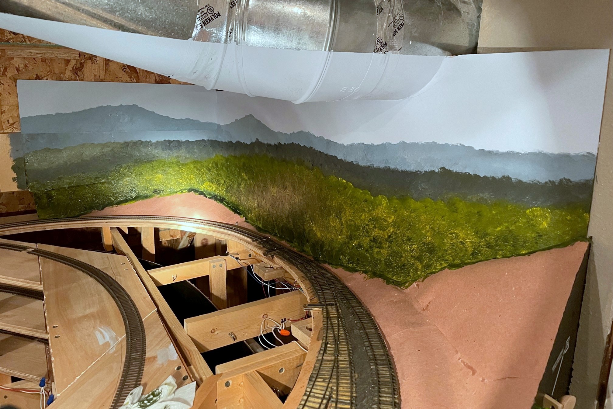
Once the distant ridge is in, step 3 is to paint the next nearest ridge a little darker but still not bright green
Next, I added some primary yellow to the palette and started moving to the second ridgeline, still using a good bit of the sky blue but now adding more yellow which makes a nice Woodland Scenics-ish green when mixed with the mars black. Once the second ridge was in, I felt it didn’t have enough definition, so I dabbed the brush in some mars black and touched the base color without mixing it in and “blobbed” in some shadows. Finally I transitioned to the larger trees near the bottom. No sky blue, just a lot of yellow and a little mars black barely mixed and blob, blob, blob, again adding some areas of shadow with a little more black in the mix.
This is the one hard corner of backdrop on the layout–I think once I play with the lighting it will be a little less stark
The result is what you see here. It’s certainly no real art, and it doesn’t look nearly as nice as the backdrops in the video. Still, I think it gives a decent impression of a deciduous forest and Appalachian ridges that doesn’t distract from the foreground. I also think the color will blend pretty well with common light and medium green ground foam and foliage. I did about 15′ of linear backdrop in under 2 hours… not a bad return on time invested. I love what it does to the layout feel, as well. For the first time since I started building the layout, when you walk into the layout room it feels Appalachian. Looking forward to painting more and improving on my bare-bones techniques!
Part of the backdrop under the stairs involves a piece of the “sky” that sticks out
This is the first section I did. It’s amazing how much less noticeable the steps are with the mountains painted
Step 1 is to outline the distant ridges in chalk, and step 2 is to paint the distant ridges a bluish gray
Once the distant ridge is in, step 3 is to paint the next nearest ridge a little darker but still not bright green
The finished scene showing the brighter foreground trees painted with yellow and mars black mix–what a difference the painted backdrop makes for the scene!
This is the one hard corner of backdrop on the layout–I think once I play with the lighting it will be a little less stark
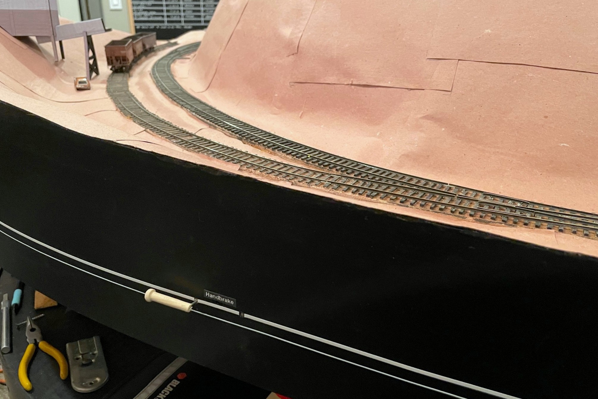
The St Charles Switcher crew sets the handbrakes to leave a string of loaded hoppers on the grade while working the yard
Gravity is a major factor in prototype railroading, but it can be quite troublesome for a model railroad. Very little real track is actually completely flat, so train crews routinely use the handbrakes on individual cars to hold them in place in yards or sidings. Not only do handbrakes hold cars in place, but in the Appalachians where I model, gravity and handbrakes were often used to move cars from empty tracks to tipple loading points, to move loads into the right track below the tipple, or even to run-around a caboose at the end of the line. Modeling working handbrakes on individual cars isn’t very practical, so what is a model railroader to do? Some install springs on the ends of a car’s axles to use friction to hold the car, but this can’t be “turned off” to allow the car to roll freely. Others use little picks they stick into the ballast to hold cars in place, but this can be destructive to scenery, and it leaves an un-prototypical giant stick next to a cut of cars. I’ve adopted a method of fascia-controlled “handbrakes” on the tracks which works well for my needs.
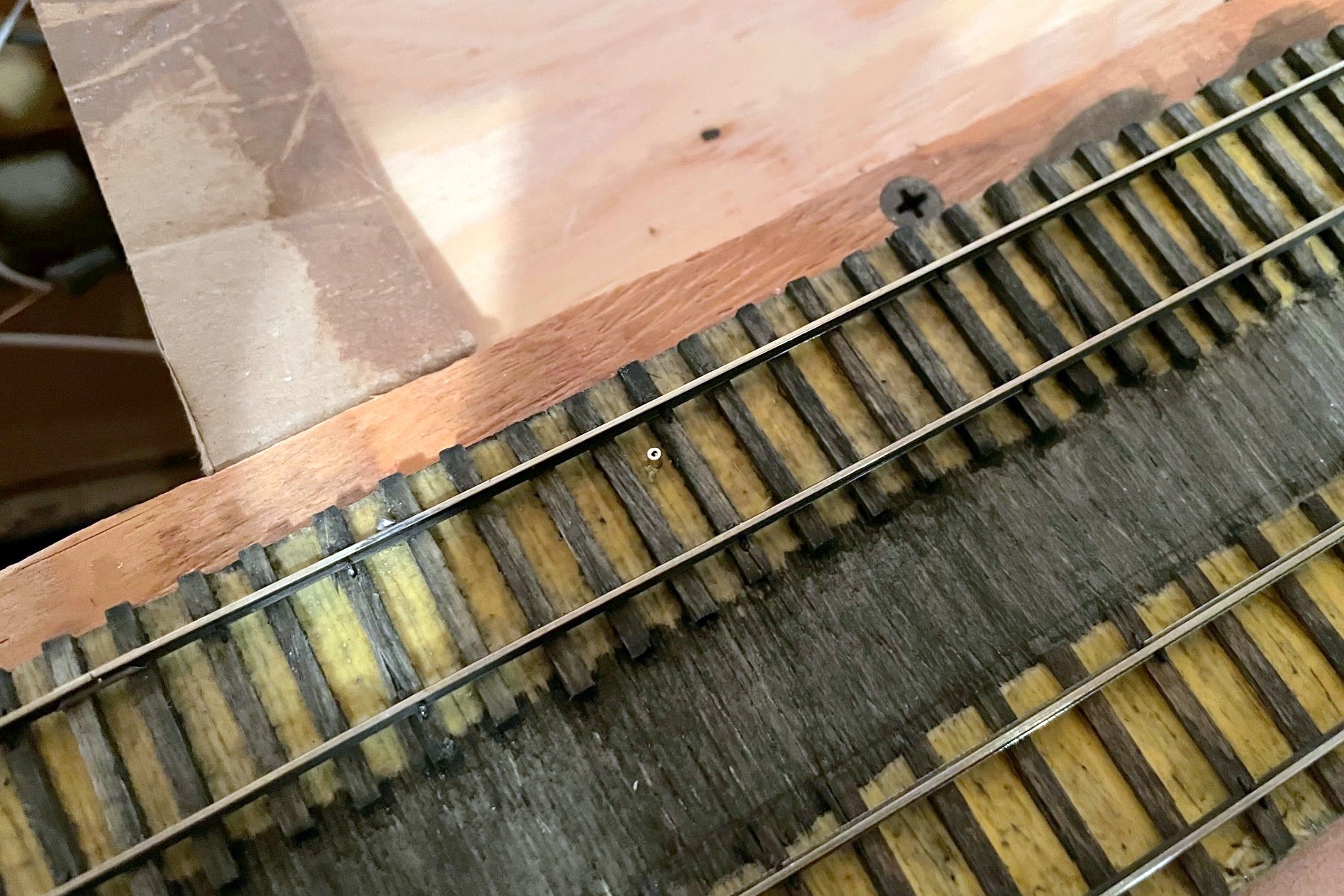
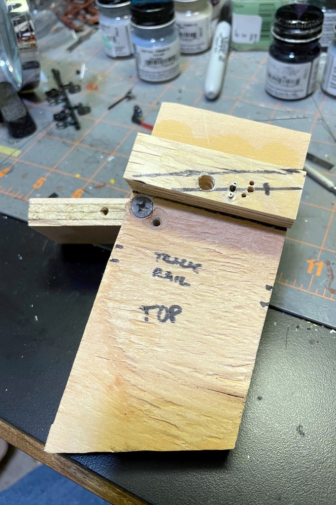
The first step of the handbrake is to locate where you want the brake, drill a hole, and insert a brass rod sleeve for the brake wire
This method is overkill if you just want to hold cars in place on a siding. For this I recommend a drop of CA, a piece of monofilament line sticking up through the tracks, or the end of a soft brush if more strength is needed–I use all of the above for holding cars in place when set out. I use the method here where I need brakes sometimes and free rolling other times, so the first thing you need to do is figure out where you need brakes. I once heard a story about a design presented to a university for a new campus that didn’t show any sidewalks. When the dean of the university asked the designer why there were no sidewalks, the designer replied “wait a year after the campus is open, then you’ll know exactly where the sidewalks need to go based on the trails through the grass.” So, where do I install brakes? Wherever I find I need them when operating trains–a question I also pose to my operators after every session: “is there anywhere you wished you had handbrakes but didn’t.” Generally speaking, they’re needed anywhere a crew will need to leave cars on a grade for a period of time to conduct other work. Since I’ve got lots of grades on the layout, I’ve currently got five handbrakes installed on the lower level alone.
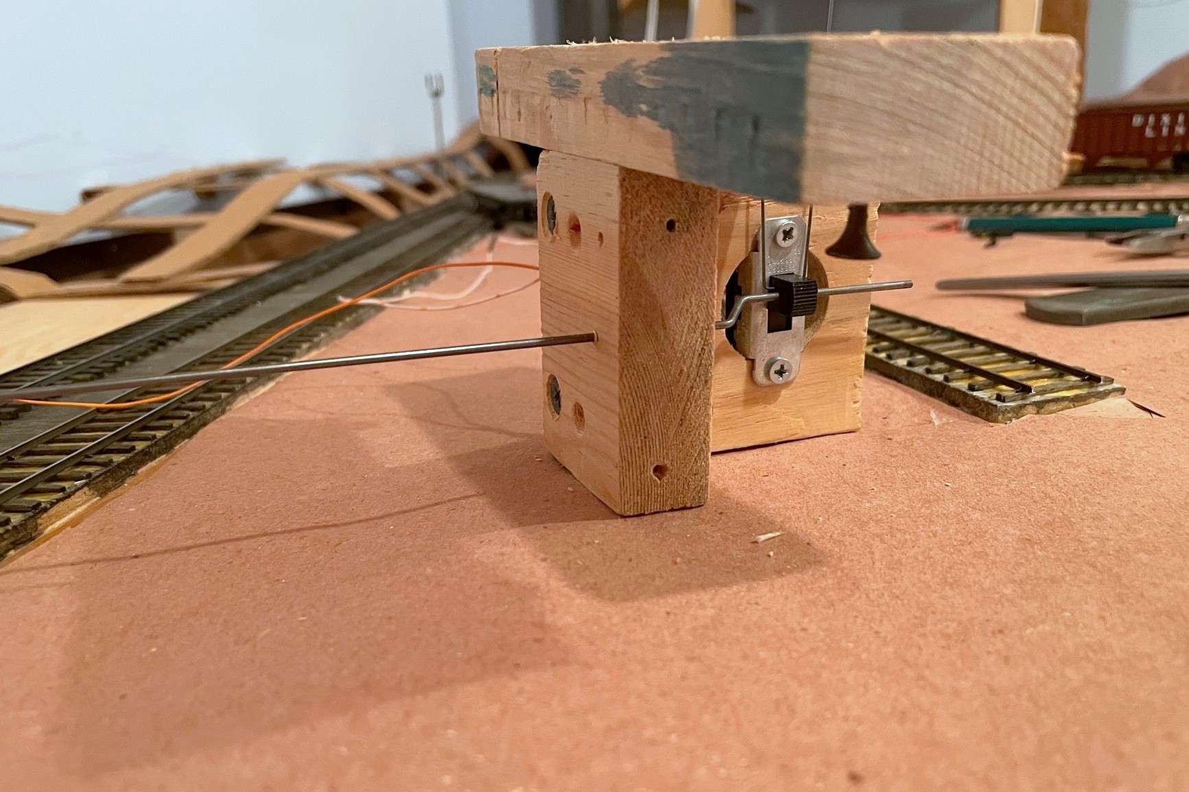
The concept of these fascia-controlled handbrakes is simple: install a movable piece of strong wire between the rails tall enough to hold an axle with a mechanism to retract it when not in use. Once you know about where you need brakes, mark that spot between the rails, and make sure the area underneath is clear enough to install a brake mechanism. Remember, the brake can really be anywhere along a string of cars, so if your ideal spot is not to ideal under the layout or on the fascia, just move it a few inches. I use 1/16″ brass tube as a protective sleeve for the .025″ steel music wire I use as the brake, so once I find a spot, I drill a vertical hole between the ties for the brass rod. I like to offset the rod about 1/4-1/3 between the rails to avoid interfering with truck bolsters (coupler trip pins will also be an issue for those who use them… in fact, a similar mechanism might work for uncoupling too, hmmm…).
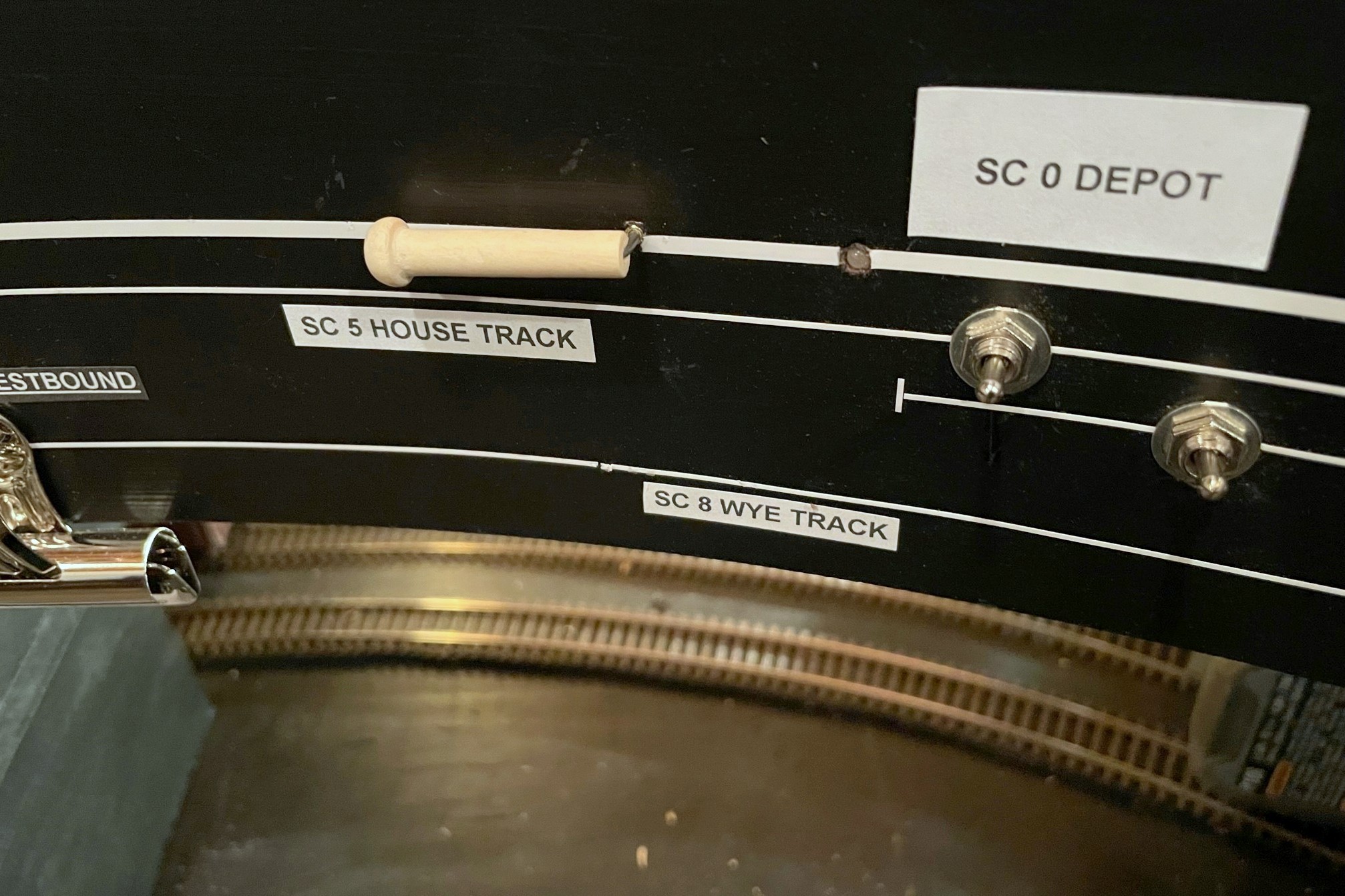
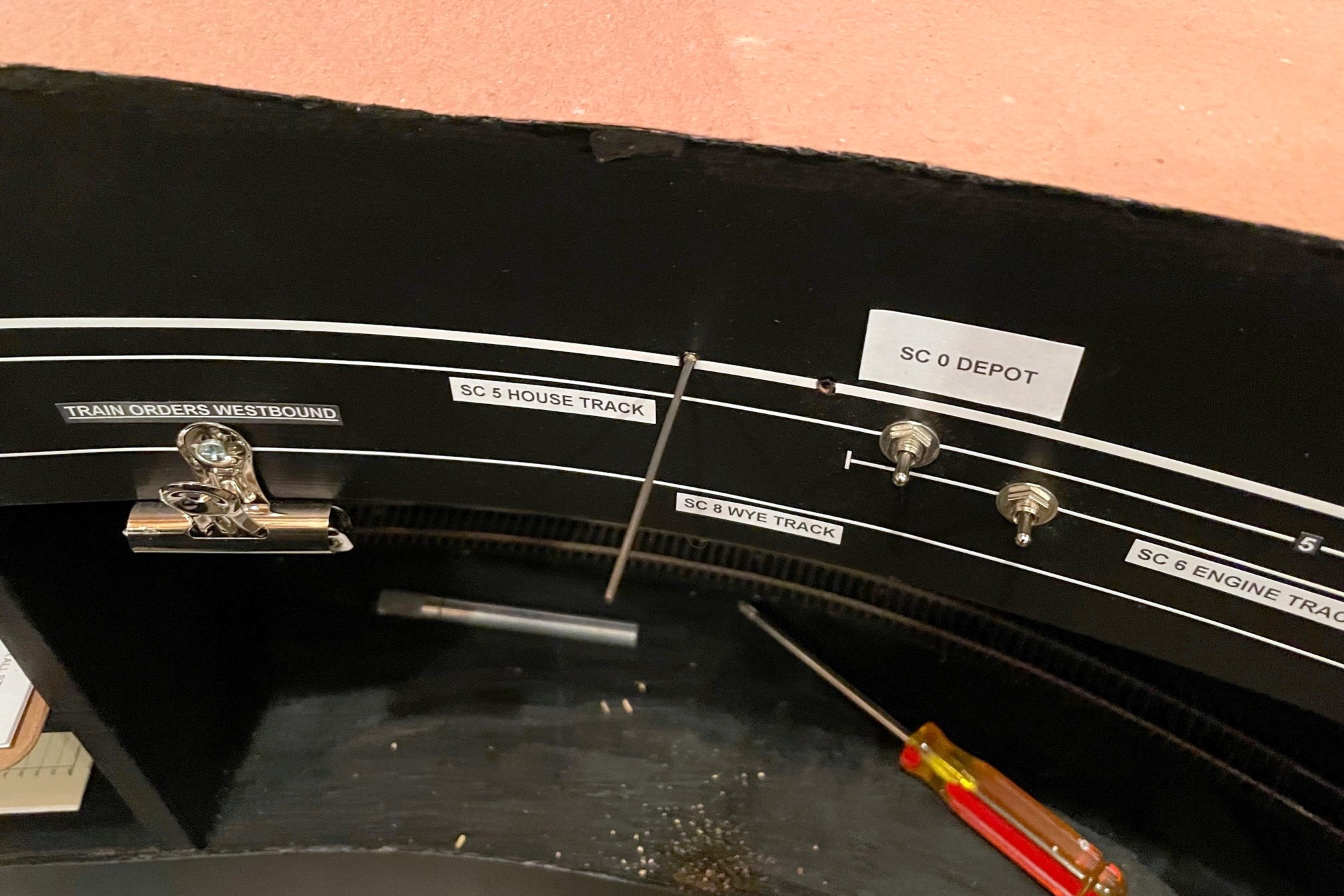
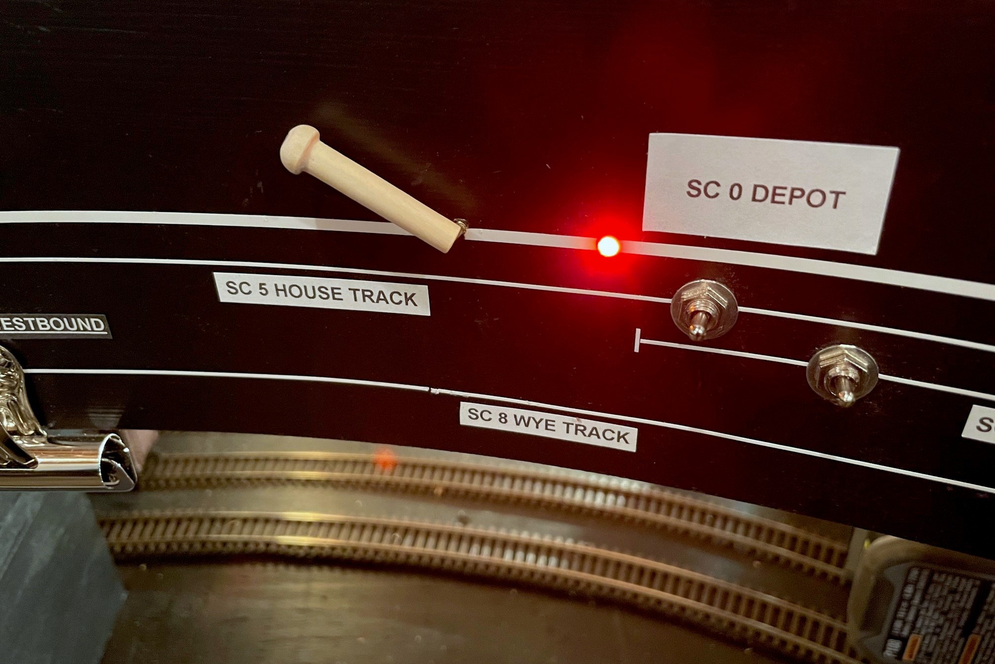
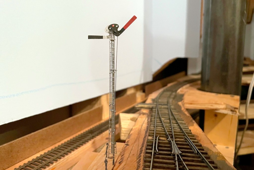
Here’s the finished control in the “off” position (in line with track)
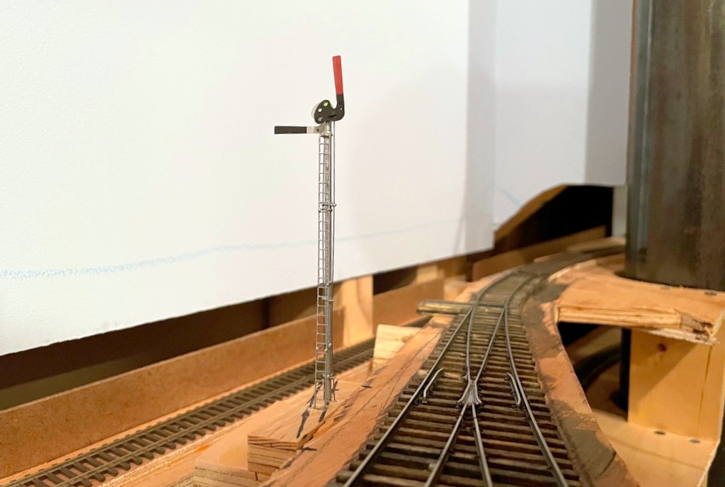
If you’ve followed me for a while, you know I’m a big fan of manual controls using slide switches–I use them for turnout controls, semaphore controls, and now handbrakes. You also know I’m a stickler for creating a fascia where the controls make sense and aid an operator instead of confusing them. In the case of the handbrake, I wanted it to be easy for operators to see when the brake is “set” and when it is retracted, so I settled on a control lever that lies in-line with the track when retracted and sits at a sharp angle when “set.” Just for good measure, I also use a bi-color LED to illuminate amber on the fascia representation of the affected track when the brake is set to help mitigate inadvertently running into a brake with the delicate footboards of a super-detailed locomotive (been there, done that).
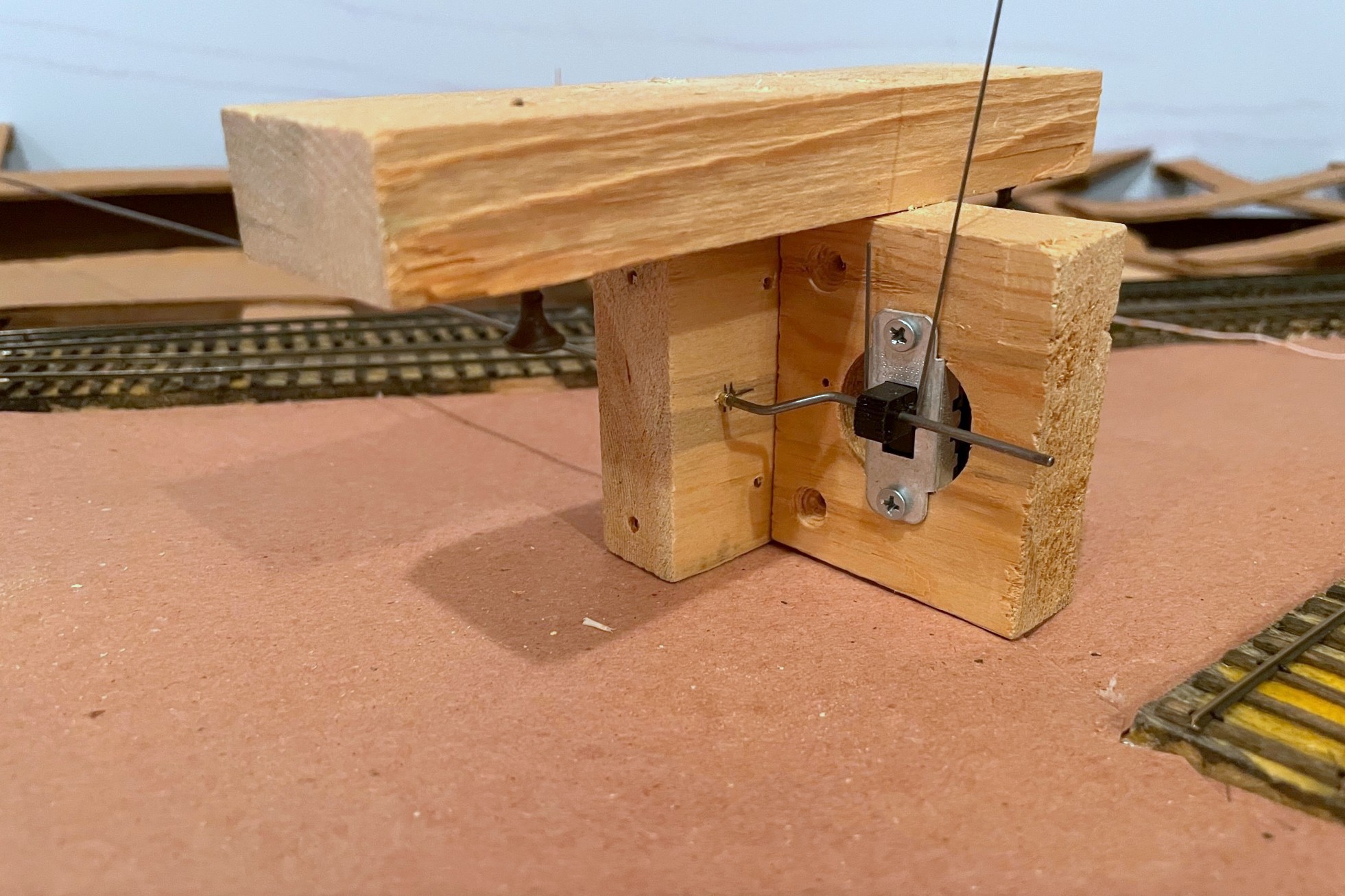
Here’s the completed brake assembly with three pieces of wood, DPDT slide switch, brake wire (vertical), and control rod (horizontal)
For the brake mechanism, I use a vertically mounted slide switch (DPDT in this case) with a 3/16″ throw–this is just enough to catch the axle of a 36″ wheel in HO scale when extended and still retract to almost rail height when recessed. The brake rod itself is a piece of .025″ music wire bent into a squared-off “J” shape running through a hole in the slide switch–initially, make this piece long enough that it will stick up about 1/2″ or more above the rails when in place. The control mechanism is a piece of thick steel rod (.062″ music wire) with a bell crank bent at one end. Th rod should be cut about 3″ longer than the distance between the brake’s track location and the location of the control on the fascia. The bell crank is offset about 1/4″ from the rod. As you can see in photos, I drill a hole in a piece of 1×3″ board centered on the slide switch and offset about 1/4″ laterally for the control rod to pass through (lined with 3/32″ brass tube for smooth operation). I also bend the bell crank at 45-degree angles instead of 90 as this allows me to make adjustments to the crank offset in either direction, shorter or longer. The structure for the mechanism is typically three boards: 1) the slide switch board with a large hole drilled out for the switch (mounted with screws), 2) the control rod board mounted 90 degrees to the switch where the bell crank is secured, and 3) the attachment board on top to make it easy to mount to the plywood sub-roadbed. I use 1×3″ pine for most of my pieces, but I may use different thicknesses of attachment plates to get the control rod at the right height for the fascia control–the brake wire can be really tall and still work, so better to have the mechanism hanging lower than to have to curve the control rod to the right height. Once I’ve got the three boards assembled with 1 1/4″ drywall screws, I disassemble it, insert the bell crank end of the control rod, insert the bell crank into a hole drilled in the slide switch, adjust the bell crank as needed for smooth operation of the switch, and reattach the boards with the screws.
The left is the front side of the assembly that will face the fascia–note the brass rod sleeve in the wood where the rod goes through
For the fascia, I drill a hole for the 3/32″ brass rod sleeve as close to horizontal as I can get it and pointed directly at the brake location on the track. I pick the spot on the fascia that allows me to do this while keeping the control rod as perpendicular as possible to the fascia (you don’t want the control rod coming out of the fascia at a strange angle if you can help it). The LEDs are nice but not necessary, but this is the step where I drill the holes, about 1″ behind the brake control. I like to drill the hole through the fascia the exact size of the LED bulb and then use a second larger bit from the back side of the fascia to create a space for the rest of the LED–this keeps the LED from popping out the front of the fascia. I use bi-color red/green LEDs which glow a nice reddish amber when hooked up to AC (e.g., DCC track bus), and I attach one lead to one side of the track bus (with a 470K resistor), the other lead to the “up” position of the slide switch, and a third wire from the center position of the slide switch to the other side of the track bus. Super simple.
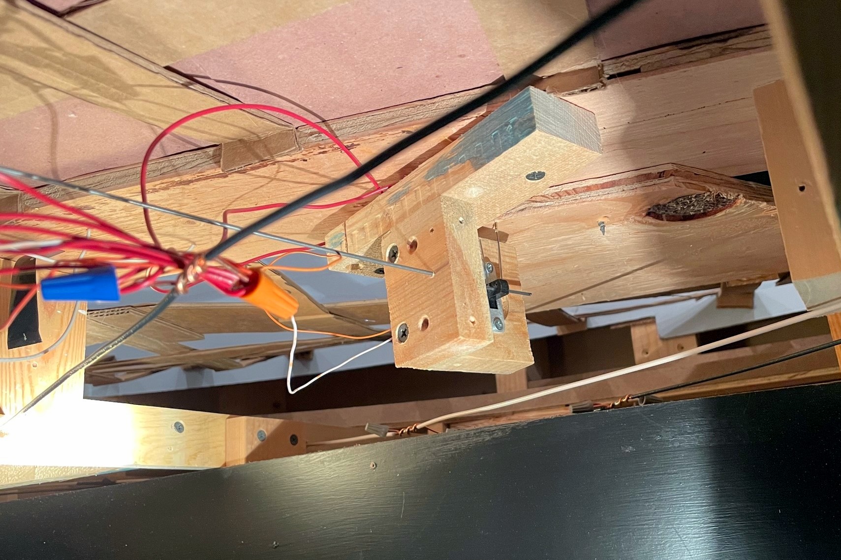
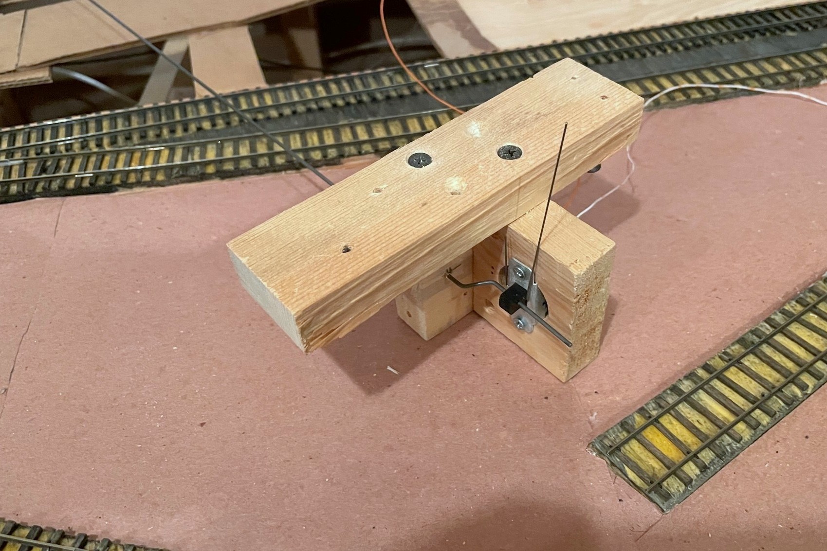
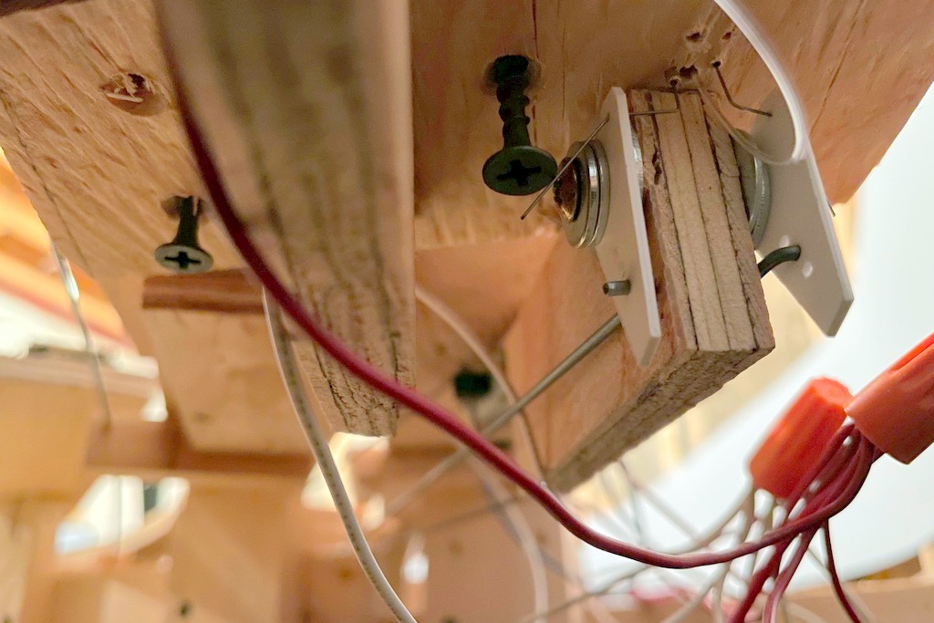
Here’s the handbrake mechanism installed under the layout–the control assembly should orient to the fascia and not the track
Mounting the switch mechanism is a bit of a pain and requires some planning and patience. From under the layout, I run the control rod through the fascia. Then I find the brass rod going up through the tracks and insert the brake rod (it helps if the brass rod is long enough to protrude beyond the plywood of the sub-roadbed). With the mounting screws on the attachment plate ready to go (screwed in so they’re almost through the board), I gently move the mechanism around until the brake wire is more-or-less vertical, the switch operates freely, and the control rod is as straight as possible between the fascia and mechanism. The mechanism is oriented to put the rod and switch perpendicular to the FASCIA rather than the track (angle relative to track doesn’t matter here). Once I’m happy with the placement, I run the mounting screws into the sub-roadbed.
With the brake in the RECESSED position, bend the control rod parallel to the ground
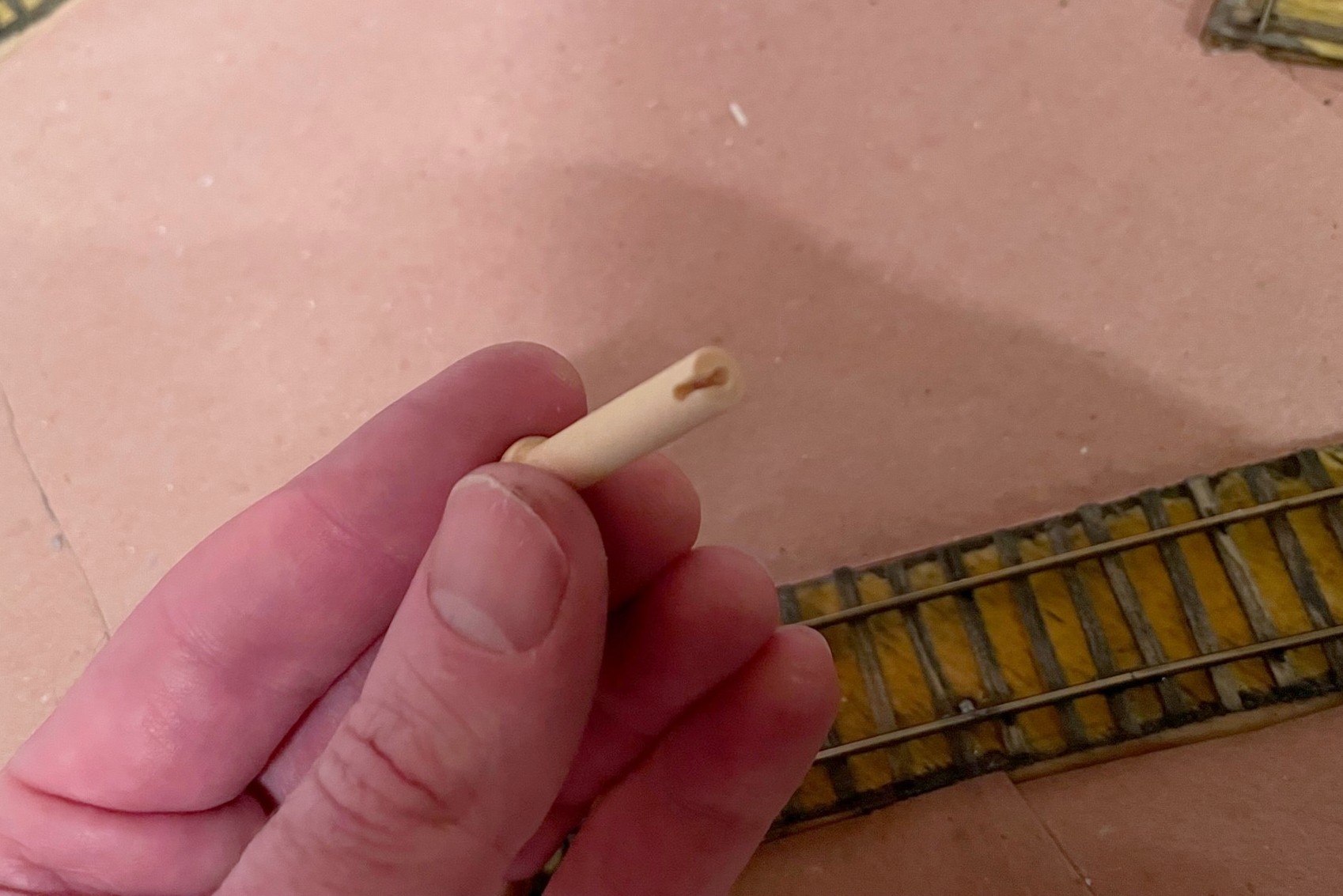
On the fascia side, I now have about 2″ of control rod sticking out. With the slide switch in the DOWN position, I then grasp the control rod with a pair of needle nose pliers flush with the fascia so the bend will be about 3/16″ from the fascia and use my hand to bend the control rod to align with my track diagram (horizontal) in the direction of the bell crank so that “up” on the control = “up” on the brake. My convention is to face the controls and bell cranks to the left, but either works. At this point, I have the leverage to test the mechanism and fix any issues. If all is good, I use a Dremel cut-off wheel to cut the end of the control rod so about 3/4″ beyond the bend. For the control lever, I use a wooden 1 3/8″ “axle peg” which can be found at any large craft store–it’s admittedly an odd shape, but it’s distinct, easy to find, and easy to use. I insert the pegs into a vice and drill a hole the exact size of the control rod about 1″ deep into the center of the peg, then drill another hole in the side about 1/8″ from the flat end into the first hole and use an X-Acto blade to create a notch between the two for the 90-degree bend in the control rod. The peg is usually a press fit onto the control rod.
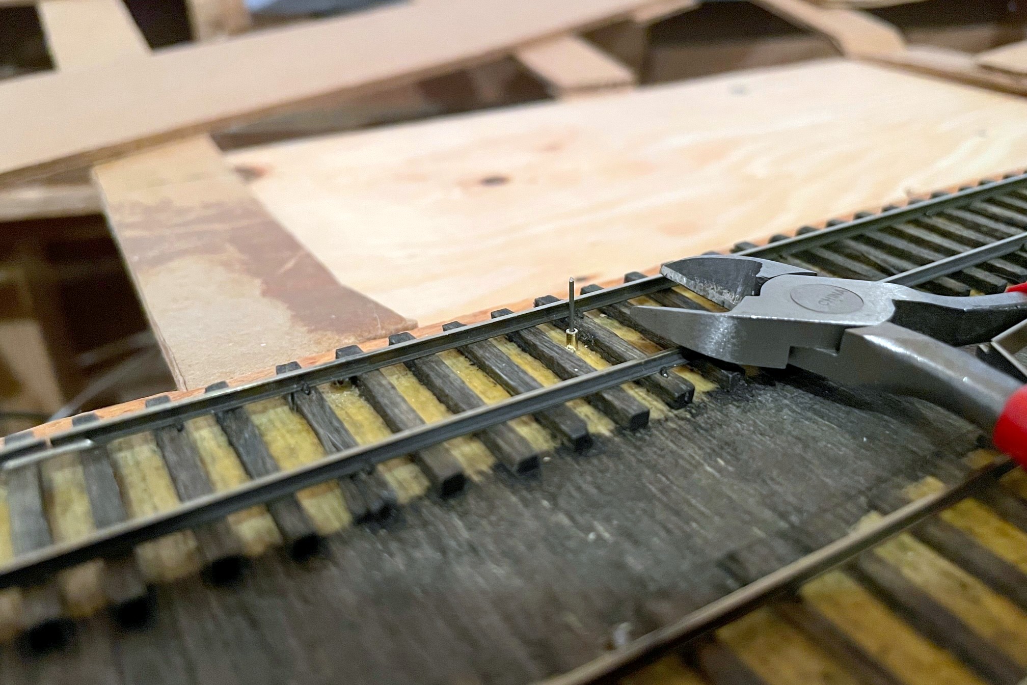
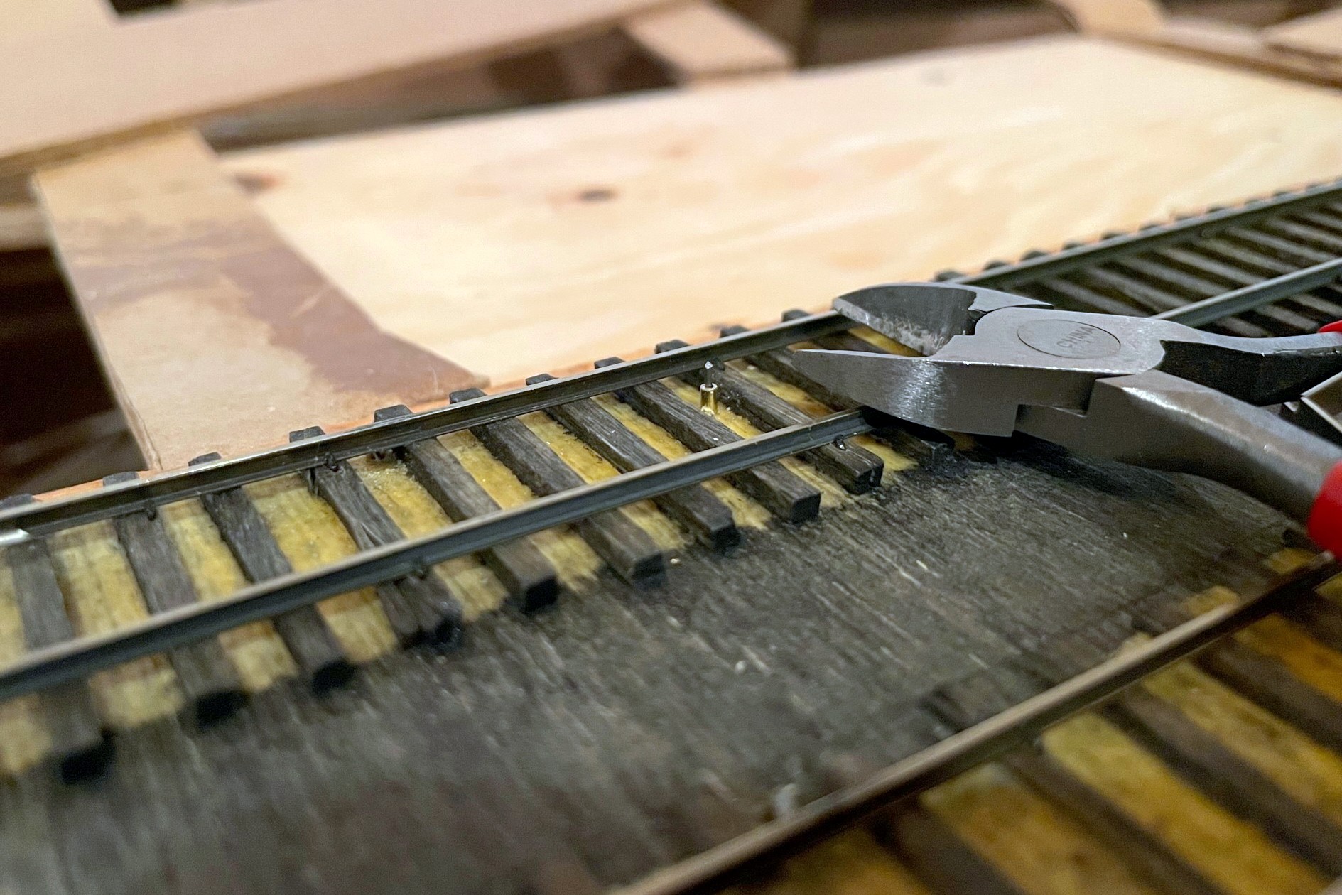
The brake wire should initially be longer than required in the recessed position
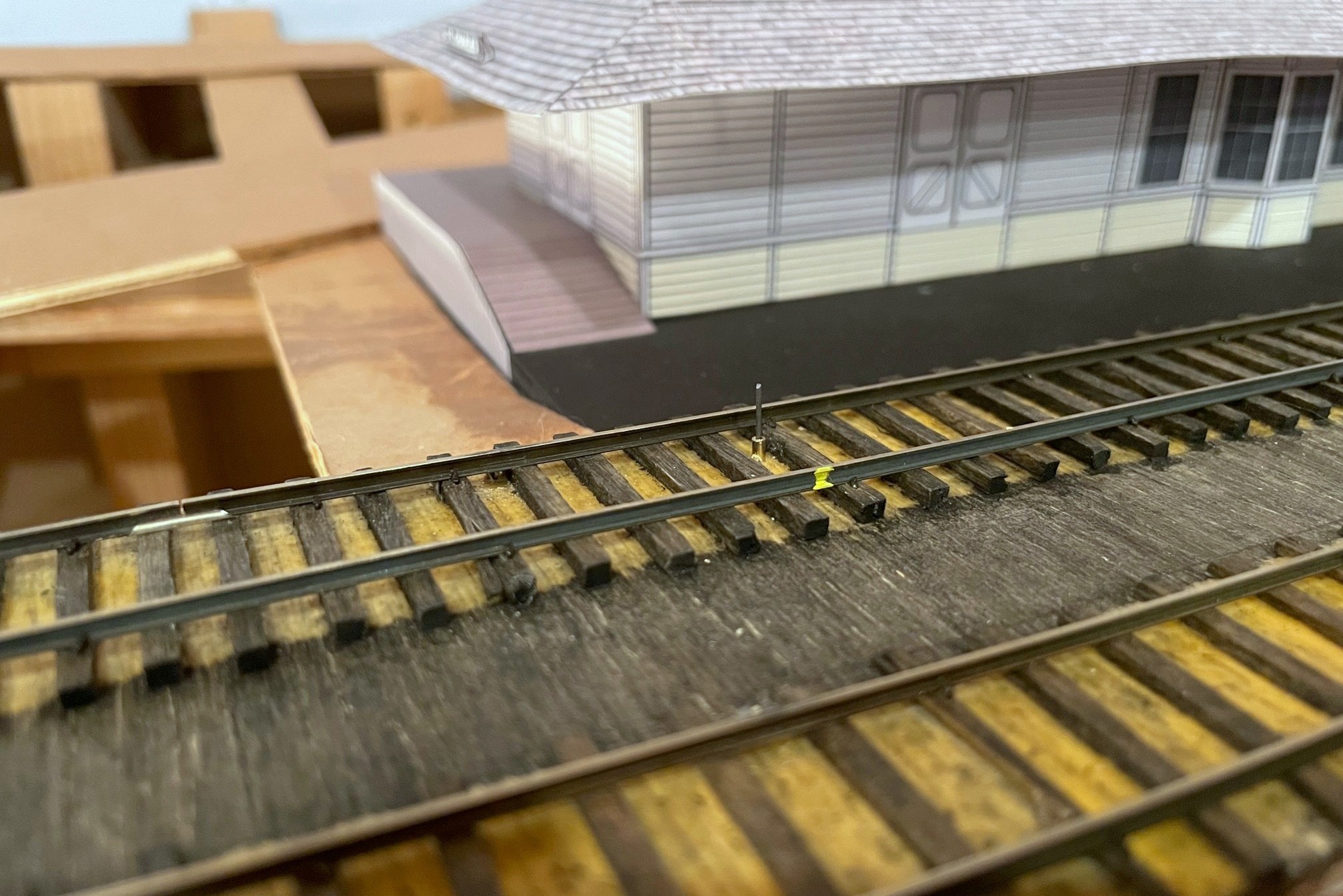
The final step is to trim the brake wire. I’ve found if I use a pair of wire cutters at rail-top level when the brake is in the DOWN (recessed) position, it is low enough for all my locomotives to clear and extends high enough to catch all my axles when needed. Because the wire’s location can be tough to see (especially when cars are over it), I use a little dab of yellow paint on the outside of the rail to indicate where the brake wire lives for easy spotting by crews.
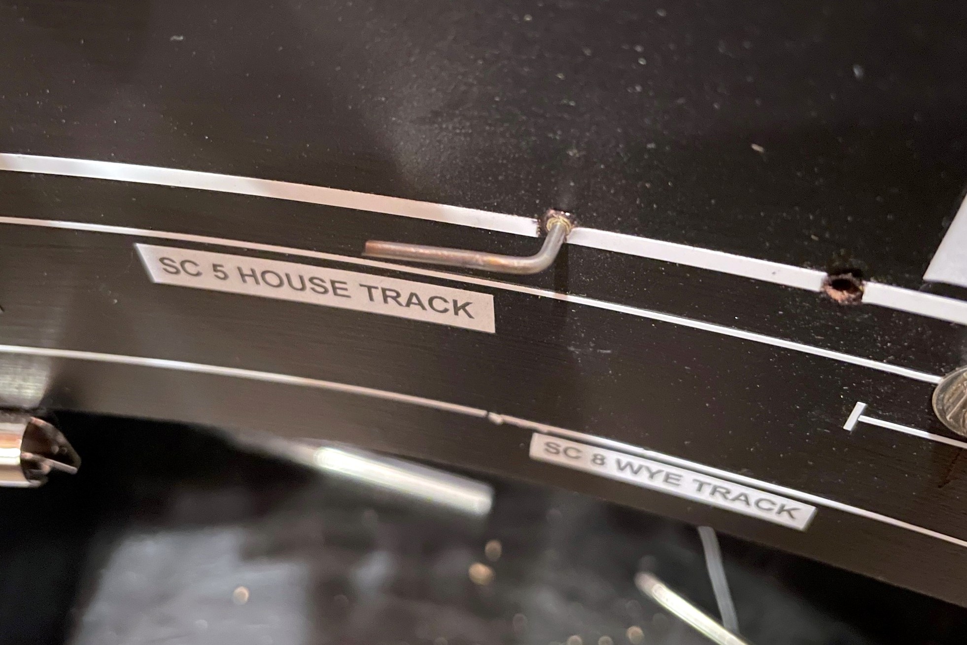
The brake wire can be tough to see with cars on top of it, so I use a little dab of yellow paint on the rail to help operators know the brake location
I’ll also share some “lessons learned” for using this type of handbrake:
The brake will find your lowest-clearance locomotive and keep it from moving until you trim the brake wire–remember this locomotive and use it to test all brake installs
If you try to pull a string of cars when the brake is engaged, you WILL bowstring every car between the locomotive and the brake off the rails (sometimes violently)
If you leave the brake “up” and roll cars into it, they will bounce back quite jarringly upon hitting the brake
If you don’t pay attention and activate the brake under a truck bolster or low-hanging part of the car, you WILL raise the car off the rails and derail it (or topple it)
Other than these “gotchas,” I’m very happy with the operational possibilities these handbrakes add to the model railroad!
The St Charles Switcher crew sets the handbrakes to leave a string of loaded hoppers on the grade while working the yard
The first step of the handbrake is to locate where you want the brake, drill a hole, and insert a brass rod sleeve for the brake wire
Here’s the completed brake assembly with three pieces of wood, DPDT slide switch, brake wire (vertical), and control rod (horizontal)
The left is the front side of the assembly that will face the fascia–note the brass rod sleeve in the wood where the rod goes through
Top view of the handbrake assembly–the top board helps to mount the assembly securely under the subroadbed
Here’s the handbrake mechanism installed under the layout–the control assembly should orient to the fascia and not the track
The control rod should protrude through the fascia at least 2″
With the brake in the RECESSED position, bend the control rod parallel to the ground
I use a wooden axle for the control rod and drill out a hole the size of the control rod along with a notch on one side
Here’s the finished control in the “off” position (in line with track)
Here’s the handbrake control in the “on” position–the LED helps alert operators that the track is not clear
The brake wire should initially be longer than required in the recessed position
With the brake wire in the recessed position, trim it to just above rail height with wire cutters
The brake wire can be tough to see with cars on top of it, so I use a little dab of yellow paint on the rail to help operators know the brake location
Here’s another handbrake on the main at a location where crews have to leave their train to work cuts of cars through a short run-around just ahead
Here’s another handbrake on a 3 percent grade above St Charles Yard–I use this one to set cars above the yard and use gravity to route them down the right track, just like the prototype would often do
As I’ve stated in previous posts, sound decoders have drastically changed my approach to DCC consisting. In an ideal world, I want all movement controls (forward, reverse, braking, dynamics) within a consist to be controlled by a single throttle, and I want only the lights, horns and bell of the lead unit to respond when an operator selects these functions. Digitrax’s “universal consisting,” unfortunately, doesn’t allow function-controlled movements like braking to go to the entire consist. Also, if you reverse the direction of the consist, you have to rebuild the consist to control both movement, lights and sound with the new lead unit. This is not a big deal for trains that only run in one direction, but every single one of my trains is an “out and back” where the lead unit of a consist switches, sometimes several times in a session. Asking operators to rebuild the consist every time they switch the train’s direction is not ideal.
Moving to “advanced consisting” (decoder-aided consisting) solved many of these problems but not all. Using the “consist” tab in JMRI, I was able to use the directional lighting features built into my Soundtraxx Tsunami 2 decoders to set the lights on the end units in a consist to “respond to consist address” but only in forward or reverse, thus solving the challenge of only getting the end lights in a consist to illuminate. The horns and bell, however, cannot be set to only operate directionally using the consist controls, so I was stuck with picking one loco in the consist to respond to all the horn and bell commands… this works, especially if all units use the same horn type, but it bothered me a bit to hear a Nathan M5 from the trailing GP35 instead of the Nathan P3 from the leading GP38. When I posed this question to a group of Digitrax experts, one of them pointed me to this video from Soundtraxx where someone had figured out how to use “alternate sound levels” function in the Tsunami 2 decoders to get directional horns, so I had to give it a try. The video left a few steps out, perhaps because they were using “simple consisting” (same address), so I had to experiment a bit to figure out how to make it work with advanced consisting, but in the end, I was able to get the consist to perform [almost] exactly as I had hoped using the following method.
The Gist
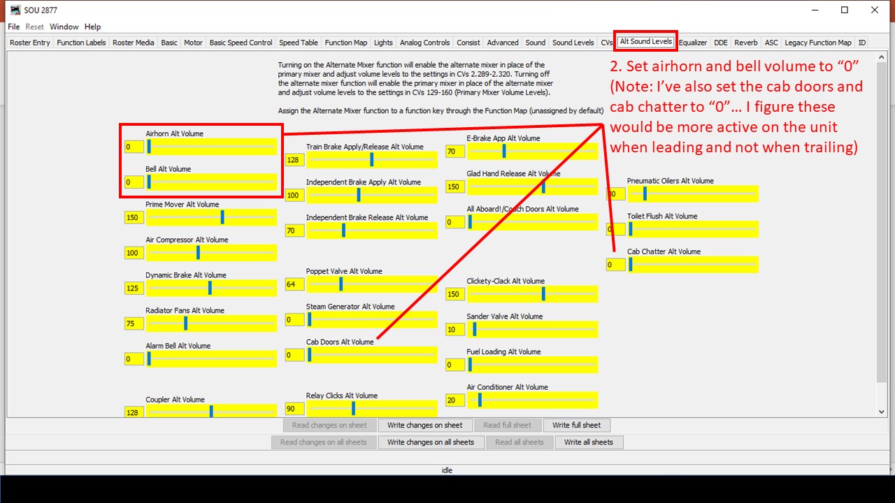
Soundtraxx Tsunami 2 decoders have an “alternate sound mixer” designed to make it easy to select a new set of alternate sound levels with the press of a function button. Additionally, the “function mapping” in Tsunami 2 decoders allows you to set any function to operate automatically when the command station commands the decoder in “forward driving,” “reverse driving,” “forward driving,” or “forward standing” conditions. The trick is to set all the alternate sound levels to match the primary sound levels EXCEPT the horn and bell which are set to volume “0,” then use the function map to configure the alternate mixer to operate any time the decoder is moving in the trailing direction (forward or reverse based on how it’s sitting in the consist), and finally to set up the decoder to “respond to consist address” for horn and bell functions. When you set up the locomotives on the ends of the consist in this manner, it has the effect of silencing the horns and bell when the locomotive is trailing and not leading. Here are the steps in JMRI.
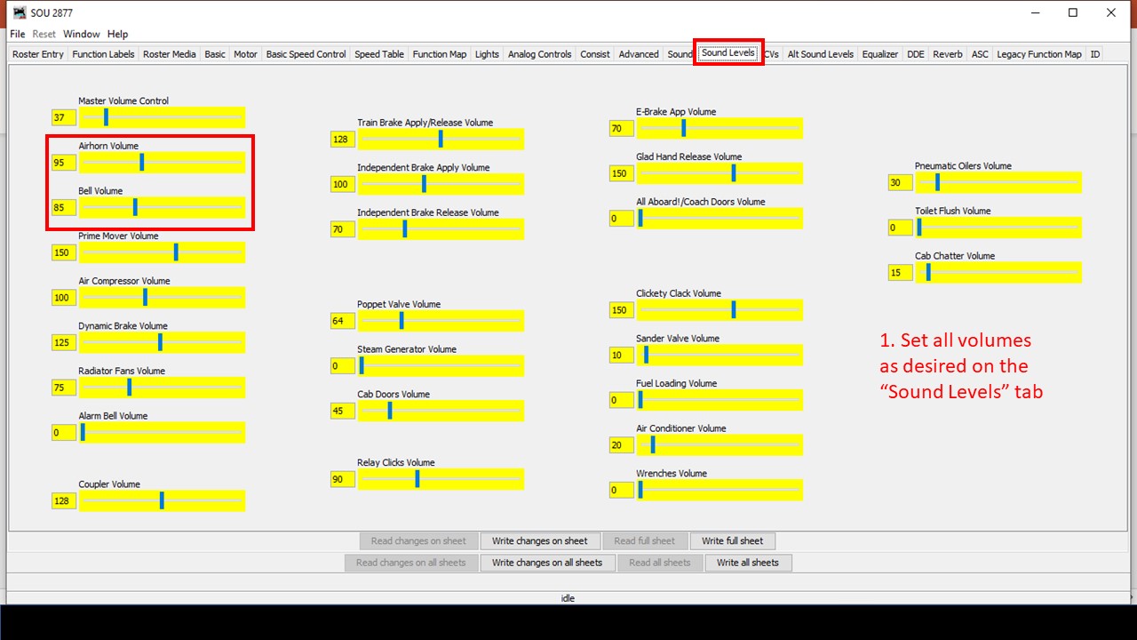
Step 1. Set the sound levels in the primary sound mixer
Step 2. Set the horn and bell to “0” in the alternate sound mixer
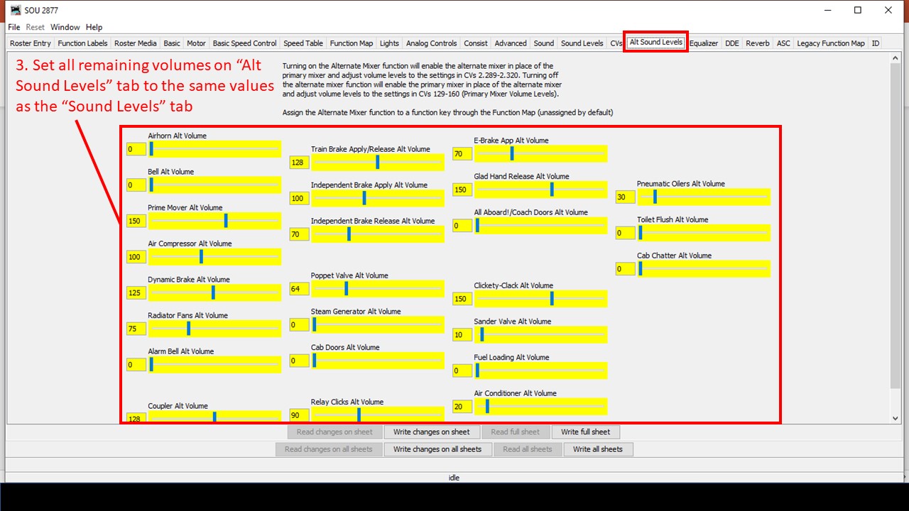
Step 3. Copy all other sound volume values from the primary to the alternate sound mixer
Step 4. Set up the “alternate mixer” to operate with forward or reverse direction (the direction in which it’s trailing in the consist)
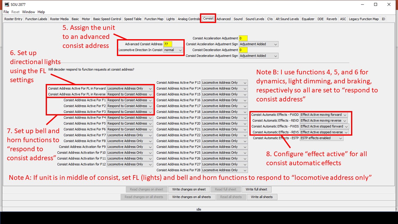
Steps 5-8. Set up the advanced consisting so directional lights and functions for horn and bells “respond to consist address” and enable the automatic functions
Some of the settings will depend on where the locomotive is in the consist and whether or not its on the end. For a locomotive in the middle of the consist, you can either set the decoder’s light, horn and bell functions to “locomotive address only” in the consist tab, or you could place check marks in all four columns in the function map (forward driving, reverse driving, forward standing, reverse standing) so only the alternate mixer with zero volume for bells and horn are used. If you change the orientation of the locomotive, you may need to change the FL settings in the “consist” tab and swap from “forward” to “reverse” check marks in the function map. Also, if you’re using a locomotive on the end that doesn’t support an alternate mixer (like the Soundtraxx Econamis I have in some locomotives), then you’ll need to pick just one of the locomotives to “respond to consist address” to provide the horn and bell for the whole consist and disable the directional checks in the function map.
That’s it! Now when you run a throttle using the advanced consisting address, the lights on the ends will be directional, AND only the horn and bell of the leading unit will respond to the throttle’s horn and bell functions no matter which direction you’re running. Click on the video at the top of the page to see this in action, and if you’ve got some even better tips and tricks for this, please leave them in a comment below!
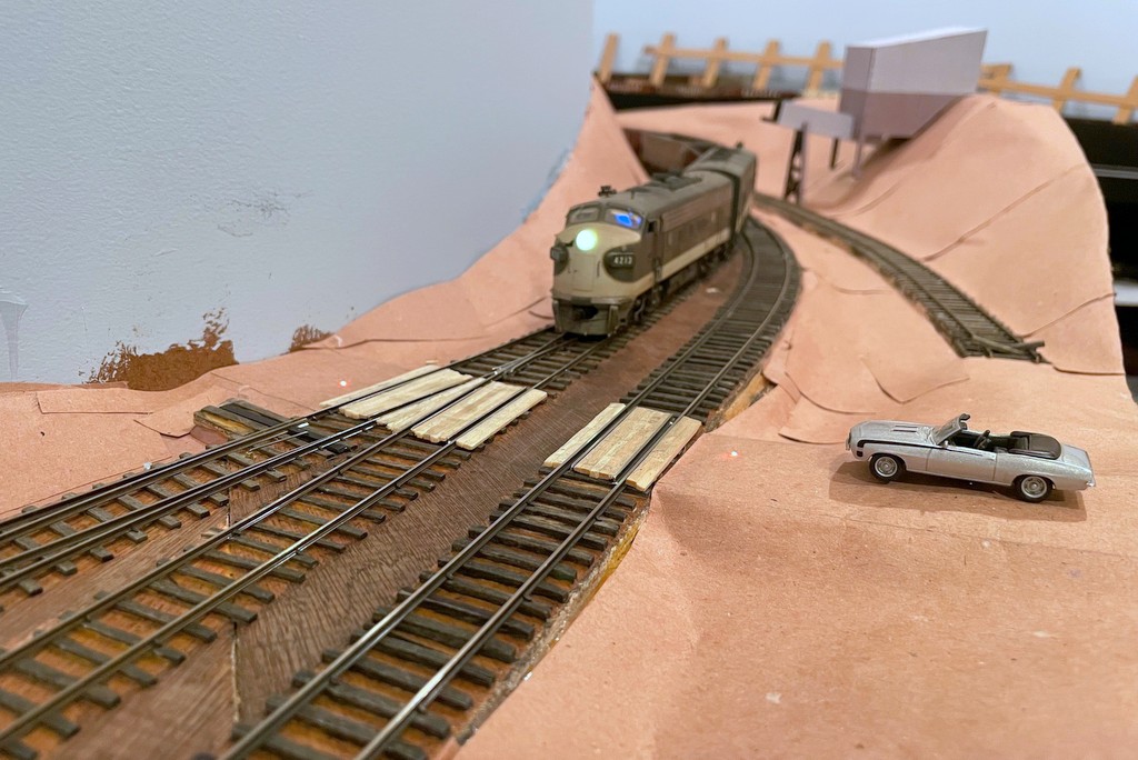
The St Charles Switcher crew throws down a couple fusees to protect the Pot Branch Road grade crossing near Mayflower
I enjoy trying to copy every element of prototype railroading I can… as long as there’s at least an element of fun in it. When I saw this short video showing a Western Maryland crew dropping fusees (pronounced “fyoozees”) to protect a grade crossing, I started thinking about how I might model this. Fusees are used by railroads for many purposes including dropping them on tracks to warning following trains of their presence–because of this purpose, fusees are designed to burn for a set time, commonly 10 minutes. Fusees can also used to protect grade crossings that don’t have flashing lights like the one in the WM video, especially when it’s dark or posting a flagman wouldn’t be practical or safe. Since I want to model nighttime ops, and I haven’t made any HO scale flagmen to post yet, I decided I wanted some simulated fusees to protect the handful of crossings I have on the layout.
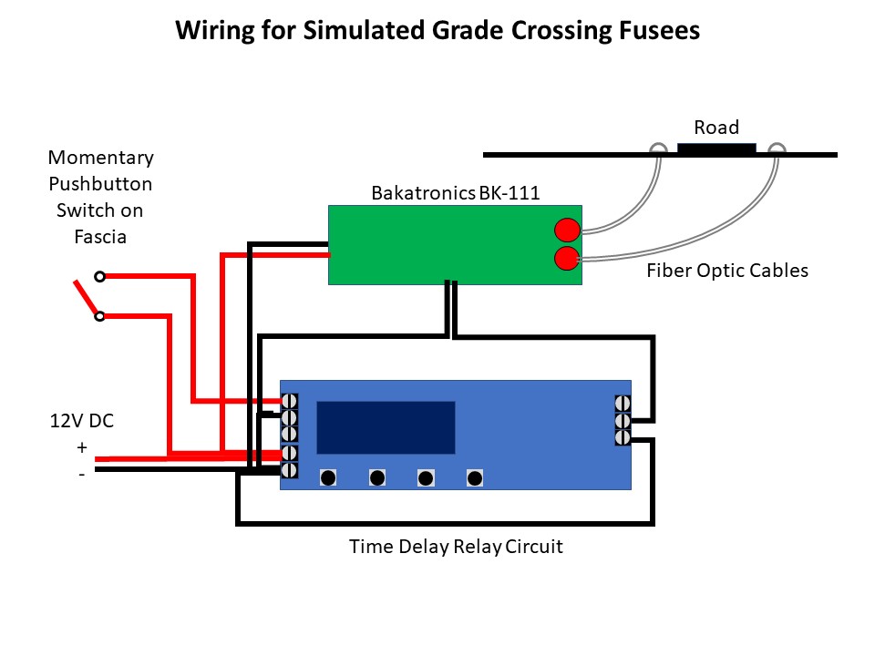
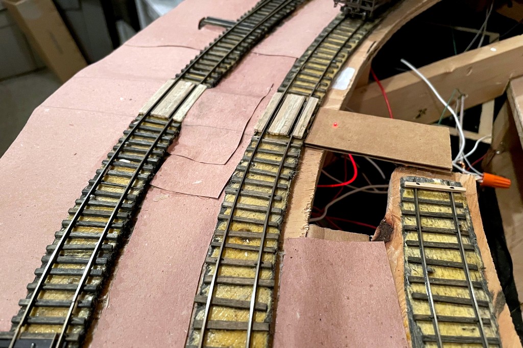
My first attempt was pretty simple and economical, just two fiber optic cables embedded into the “road” (it’s just paper and cardboard at this point) on either side of the grade crossing routed to a bi-color LED that I connected to the DCC track bus (creates a reddish orange glow) and a simple SPST push-button switch. To keep the fiber optic cable from falling through the road, I melted the end into a mushroom shape by holding it near a hot soldering iron. The other ends were taped together and inserted into a piece of shrink tubing around the LED. It was functional enough to protect the crossing, but I really wanted a way to 1) put the fusees on a timer, and 2) make them look a little more realistic.
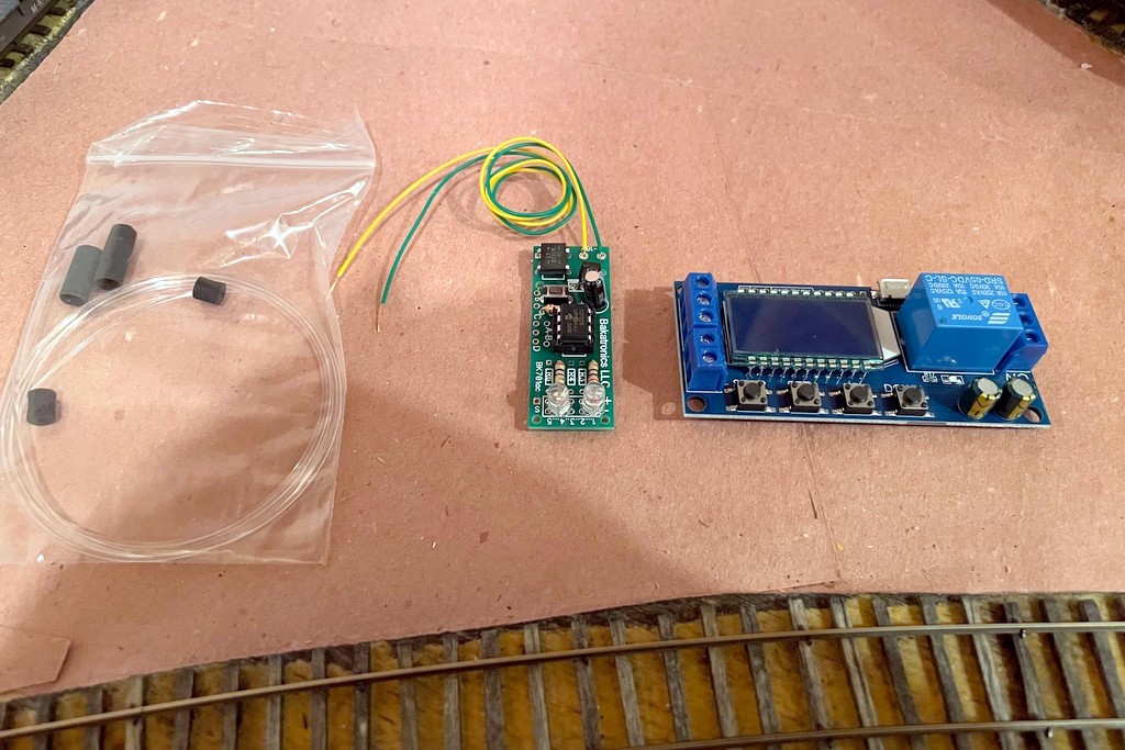
The basic parts to make a simulated fusee including fiber optics, the Bakatronics flares / fusee circuit, and the timer circuit
The timer issue was solved by searching Amazon and looking at a lot of different timing circuits. I finally settled on this one, though it’s probably overkill. I like it because you can choose one of several timing modes (fun to play with for other projects), you can set the timer for however long you want to keep the relay “on,” and you can easily see the timing settings on the display. To make them more realistic, I started with an internet search for “model railroad fusee,” and after chasing through some links in model railroad boards, I discover the Bakatronics BK-111 “Simulated Flares / Fusees Kit.” It looked promising, especially since it’s designed to power two fusees that “light” and extinguish several seconds apart (like one person is walking a short distance between lighting them, just like a grade crossing). I ordered two just to make sure it would work, and I was not disappointed! When activated, they “light” at different times, flicker independently for a while, then the first one goes out, then the second with a nice slowly diminishing burn out… really cool looking!
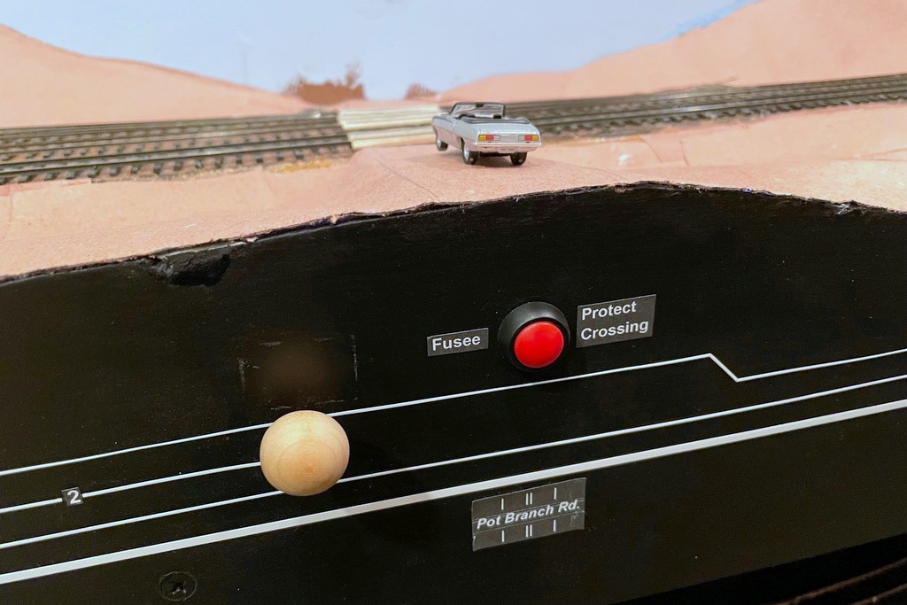
The fusees are controlled with a simple momentary SPST switch on the fascia
The Bakatronics fusee circuit is designed to work with either a momentary switch (stays on for about 30 seconds) or an on/off switch (stays on as long as the switch is closed). Instead, I wired the fusee circuit to the timer circuit so I could set the time the fusees stay lit exactly, and all the operator has to do is push a button once. I use a 4:1 fast clock, so a 10-minute burn should last about 2.5 minutes / 150 sec. The Bakatronics circuit add some time on its own, so I found a setting of 135 sec on the timer keeps the fusees lite for about 10 scale minutes, and like the prototype, the crew only needs to worry about whether or not to put down another set of fusees (push the button again) if the first set “burn out.” Both the timer circuit and fusee circuit run off a ~12V DC bus I have running around the fascia, previously to power semaphore lights. Here’s a video of the fusee in action…
We used these on my last operating session, and I thought they added a neat bit of prototype thinking for the crews–we had to think about protecting the crossings while moving the trains, and the flickering fusees gave a visual representation of the action taken. I can’t wait to try them at night when I’ve got the final lighting installed!
The basic parts to make a simulated fusee including fiber optics, the Bakatronics flares / fusee circuit, and the timer circuit
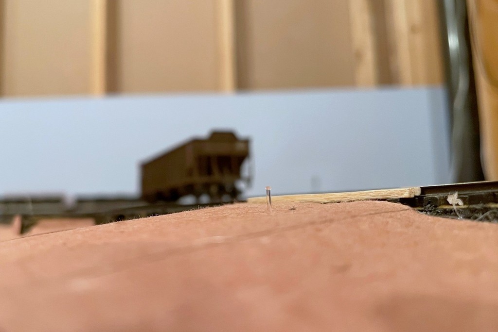
Here’s the end of the fusee pulled out of the “road” for better viewing… just the end of a fiber optic cable melted into a mushroom shape
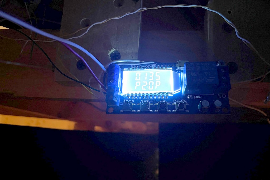
Here’s the powered timing circuit showing mode “P2” (reset time if pushed again) and “135” second of “on” time once activated
The fusees are controlled with a simple momentary SPST switch on the fascia
A look at the glowing fiber optic cable under the layout that lights the fusee
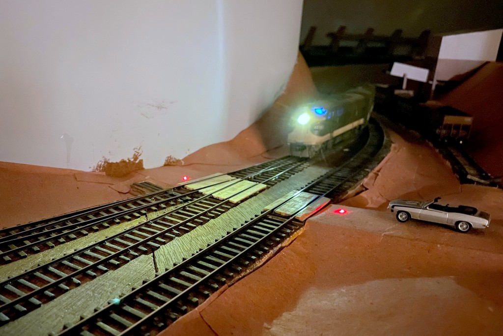
The St Charles Switcher crew throws down a couple fusees to protect the Pot Branch Road grade crossing near Mayflower
The layout’s not set up for night operations yet, but once it is the fusees will look spectacular!
Patrick and Stuart work Mayflower with the St Charles SwitcherPatrick runs the St Charles Local figuring out how to get 10 pounds of cars to fit in a 5 pound sack
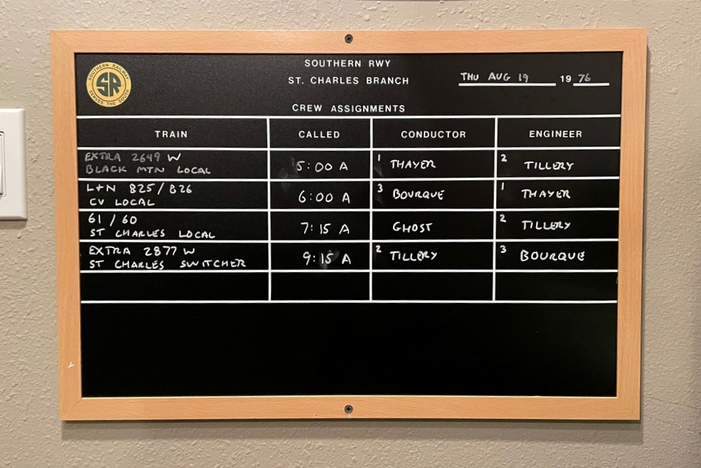
Or is it “operating session Aug 2, 1976?”… Regardless of the date, it was a lot of fun hosting two great friends, Stuart Thayer and Patrick Tillery. This was the first-ever 3-operator session on the layout, and despite only having one of the two decks complete, it still took the three of us the better part of three hours to run four trains. Part of that is because I know Stuart and Patrick are both experienced operators and prototype buffs, so we put some “veteran mode” rules into effect. In addition to the normal rules of “get the cars where they need to go,” “follow signals,” and “follow the timetable and orders,” we had to protect crossings (more on that in a later post), unlock/set/lock semaphores to protect the branches we were operating, cut cars to avoid blocking a new road across two yard tracks, and follow all blocking instructions including placing all loads ahead of empties.
Trains included a “Black Mountain Local” that simulated bringing in the previous night’s haul from the non-existent upper-deck tipples, an L&N “CV Local” to handle the L&N’s trackage-rights agreements at two tipples, Train 61/60 the “St Charles Local” bringing empty hoppers out of Andover (staging) and returning with loads, and the “St Charles Switcher” working St Charles area tipples and the Baileys Trace Branch to Mayflower. With the “veteran mode” rules in effect, even the simplest of trains still took a while to operate. Just the movement of the Black Mountain Local out of the helix (including a stop to reset the semaphore) and blocking in the three-track yard took a full scale hour (15 minutes real-time). Despite the simplicity of the St Charles Local’s job (bring empties, pick up loads), the yard’s prototypically small size creates the need to use the tracks and wye creatively to swap out cuts, and the instruction that all empties (in this case empty covered hoppers) have to go behind the loads, drives the sequence of picking up cuts.
Having completed work at Baker, Patrick slows the mine run to a crawl on the way back to Mayflower as Stuart protects the crossing with fusees
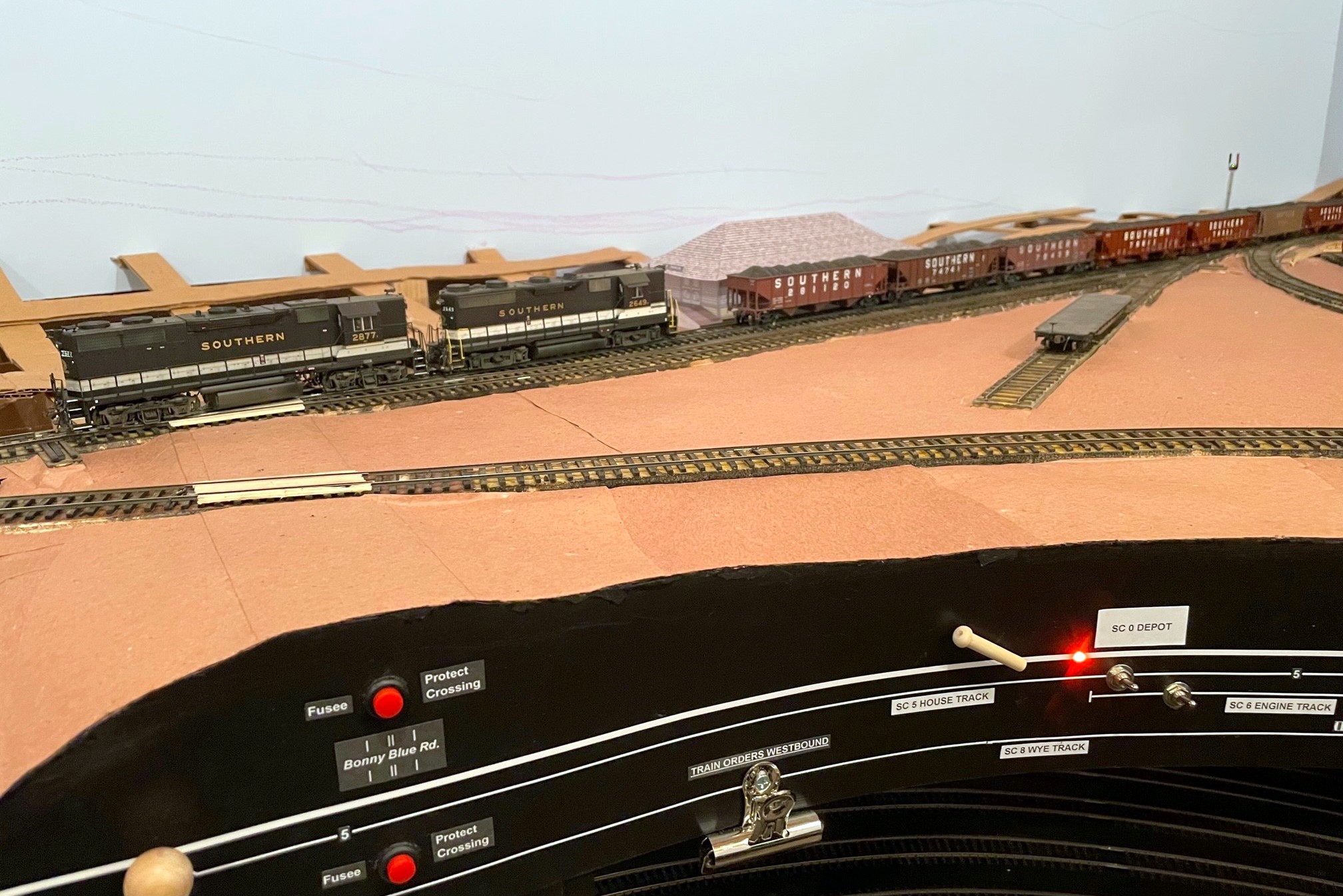
Growling L&N C420 1317 plied the Southern’s rails without incident with Stuart at the throttle, but his luck was not to hold when he took the throttle for the St Charles Switcher with GP38AC 2877 and GP35 2649 at his control. Let’s just say that there is a certain switch at Mayflower that 2649 decided it needed to jump every time, and it only needed to cross that switch 18 times to work the tipple. Despite several breaks to ensure proper gauge and freedom of motion in 2649’s trucks and tweaking some spots in the switch with a gauge and pair of pliers, 2649 was determined to stay on the ground. Of course, now that the session is over, 2649 navigates that switch just fine… sigh. I still have a long way to go until things are bulletproof.
First use of the new “fusees” I’m installing at all the grade crossings
First use of the new-and-improved crew assignment board
First time a “tipple” has been in place at Baker (a new mock-up)
First use of a new “speed-retarding system” on the steep portions of the St Charles Yard (spaced-out monofilament line)
First use of the new “safety slogans”… and no one was seriously hurt 😉
And of course some areas for improvement and “lessons learned”:
Too many derailments–I still need to improve my trackwork to make it bulletproof
I need to make blocking instructions more prominent if I want them to be followed
I don’t think the use of the train-order semaphore in St Charles is as understandable as it needs to be
I still need to work on the crew assignments to better balance how much each operator works
The St Charles Switcher arrives back in St Charles completing the ops sessionCrew assignment board for the session–I modified it halfway through to give “operator 1” more jobs… still working on balancing things
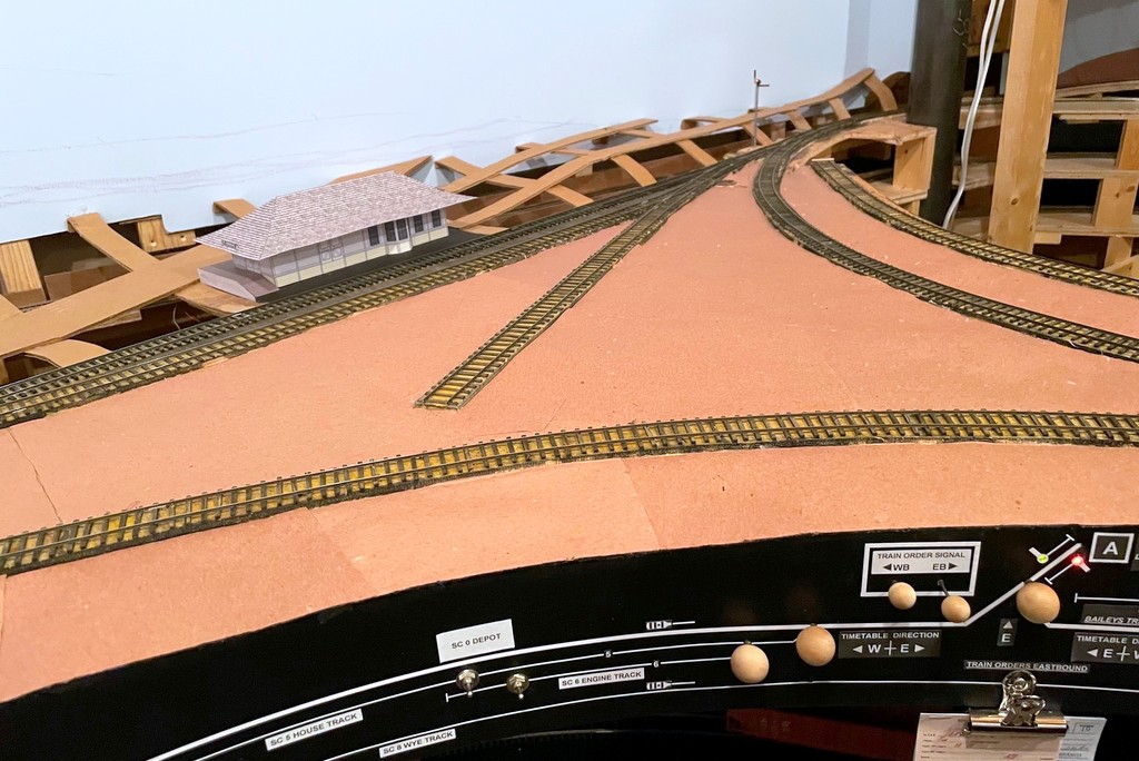
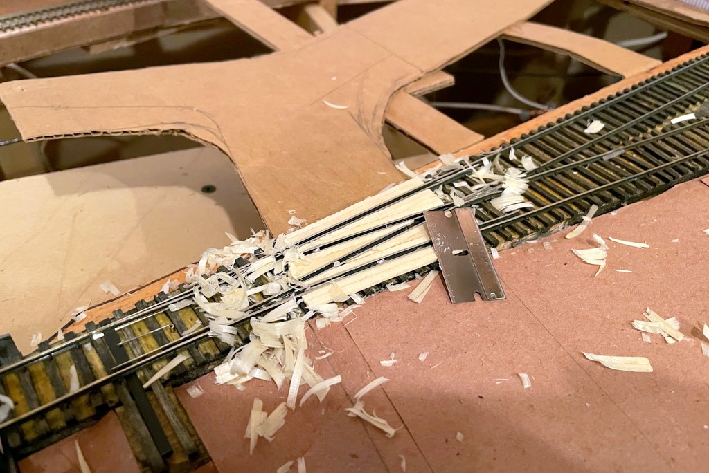
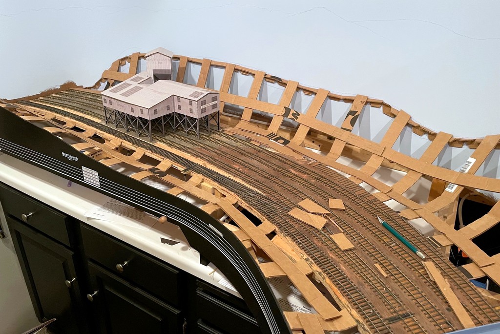
The basic scenery form is now almost done in St Charles–just some cardboard strips and red rosin paper… and lots of glueThe almost finished crossing after whittling, sanding, and scribing lines and bolts with an X-Acto blade and thumbtack
Just a quick progress update. After procrastinating and working on a semaphore, a station mock-up, and even safety signs, I’ve finally started work on the scenery again. Using the same “paper shell” method of cardboard strips, red rosin paper, and lots of hot glue, I’ve been able to get the wye in St Charles filled in with the basic land form. Of course, putting in the cardboard underlayment for the roads got me thinking about grade crossings, so I had to pause again and put in 6 grade crossings using rails and wood. Pretty simple and nothing profound, but I’m happy with the way they’re turning out. I didn’t worry about vertical height of the wood initially, only horizontal placement. I used a razor blade to whittle the wood down to rail-height level (a little tricky and scary, but effective), then used a little sandpaper and a “bright boy” track cleaner to ensure the wood doesn’t stick up and cause electrical contact issues.
That’s all for now.
The basic scenery form is now almost done in St Charles–just some cardboard strips and red rosin paper… and lots of glue
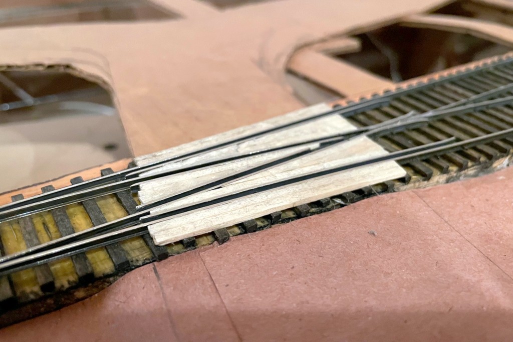
Step 1 of a complex grade crossing–adding the guard rails (extending the existing guard rails in this case)
I used full size ties and wood glue to fill in between the guard rails, then used a razor to whittle everything down to rail-height
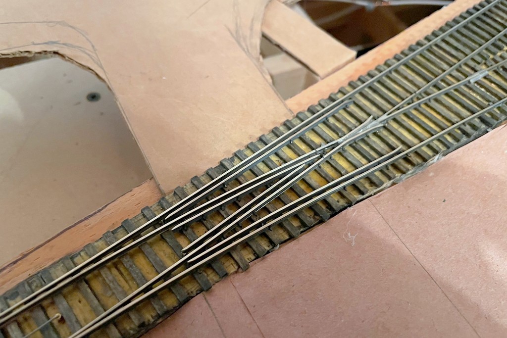
The almost finished crossing after whittling, sanding, and scribing lines and bolts with an X-Acto blade and thumbtack
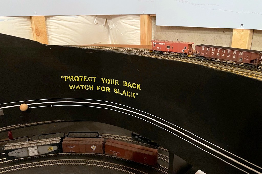
“Protect Your Back Watch for Slack” safety slogan in the yard at St. Charles
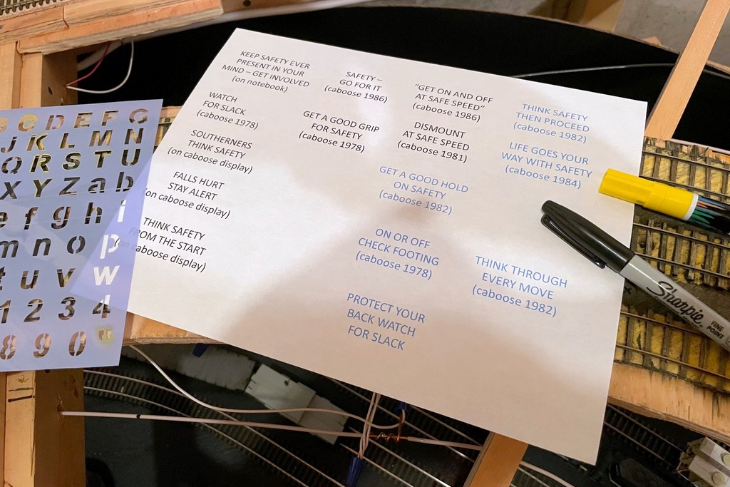
Real railroaders are inundated every day by safety slogans. This focus on safety appears to have ramped up in earnest in the 1970s with slogans appearing on all sorts of company publications, in shops, and on rolling stock like cabooses. I thought it would be fun to bring some of these prototypical safety reminders to the layout.
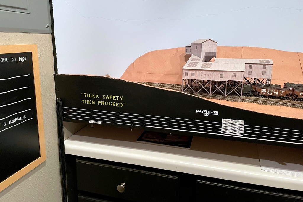
Safety slogan “Think Safety Then Proceed” occupying a corner at Mayflower
The first step was to determine what kind of safety slogans the Southern used. I found the best place to find them was just above the steps of a caboose, so I pored over hundreds of photos of Southern cabs, zooming in over the steps to see what slogans I could make out. I was able to capture more than a dozen slogans including the following:
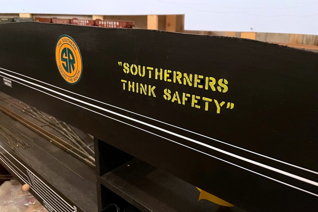
“SOUTHERNERS THINK SAFETY”
“WATCH FOR SLACK”
“GET A GOOD GRIP FOR SAFETY”
“GET ON AND OFF AT SAFE SPEED”
“ON OR OFF CHECK FOOTING”
“THINK SAFETY THEN PROCEED”
“LIFE GOES YOUR WAY WITH SAFETY”
“SAFETY – GO FOR IT”
“DISMOUNT AT SAFE SPEED”
“PROTECT YOUR BACK WATCH FOR SLACK”
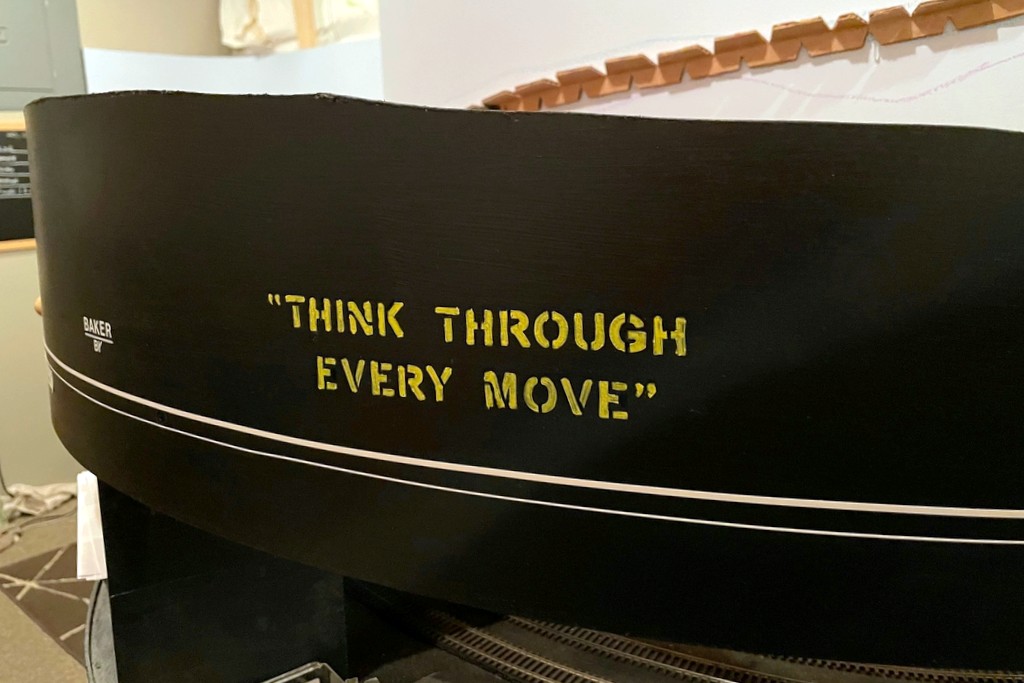
“THINK THROUGH EVERY MOVE”
“GET A GOOD HOLD ON SAFETY”
This safety slogan is the most unique to the Southern, so I placed it next to the Southern logo on the fascia
Armed with these slogans, I headed off to Hobby Lobby to pick up the closest lettering stencil I could find in the 3/4″ size range, a yellow paint marker, and a black paint marker – less than a $10 investment. I selected a few blank spots of fascia around the layout and used masking tape to provide a level reference line for the lettering. I just hand-held the stencil against the fascia, applied some yellow paint marker in the correct letter, and wiped the wet paint off the template. I carefully held a paper towel up to the freshly painted letter and dabbed it dry without smearing–this not only allowed me to move on to the next letter quickly, but it helped to created a worn and mottled look to the letters that I liked. Once the upper line was done, I measured and picked the middle point of the line, reset the masking tape for the lower line, and started with the middle letter for the lower line to keep things centered.
I decided to add the quotation marks as well. They appear on some of the slogans (not all), but I think it helps make it clear that these are pulled from somewhere instead of just being a random sign on the fascia. The template didn’t have the quote marks, so I used an X-Acto blade to make my own stencil in a blank spot on the plastic template. After things dried, I used a combination of the black paint marker and a sharpie to clean up around the edges. Finally, I used the Sharpie to draw in some extra stencil lines across the letters using pictures of actual Southern stenciling as a guide (for example, a line under the top part of the “T” and lines across the top and bottom of the “C” and “S”).
Ok, there’s one more project down that’s been rattling around in my brain and one less excuse to procrastinate on getting back to scenery…
This was a simple project that only required a list of slogans, a cheap lettering template, a paint pen and a Sharpie
This safety slogan is the most unique to the Southern, so I placed it next to the Southern logo on the fascia
Safety slogan “Think Safety Then Proceed” occupying a corner at Mayflower
This safety slogan seemed particularly appropriate for a switching-based layout
I put the “Protect Your Back Watch for Slack” slogan in the yard at St. Charles
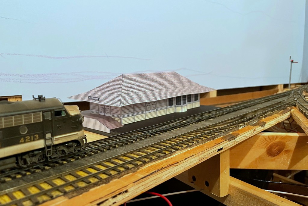
The St Charles local slows to pick up orders from the operator at the St Charles depot
This update is proof positive that I will do anything to procrastinate on building scenery… Of course, in my mind I’ve justified this delay as important because I need to be able to visualize the scene in St Charles before putting in the basic landforms. Sure, let’s go with that very logical explanation!
Several months ago I shared my plan to build mock-ups of the major structures on the lower level, the first of which was the Mayflower tipple which has appeared in many updates since it was built. I don’t want to build the permanent structures until construction on the upper deck is complete, but I’d like to have some of the key buildings represented both to visualize scenes and to give operators something better than just a block of wood to represent the buildings they’re working. Creating these mock-ups also requires me to build scale drawings (in MS PowerPoint) which, in theory, will make it MUCH easier to build the actual structures down the road. Of course, PowerPoint makes it easy to add colors and textures, so why not?
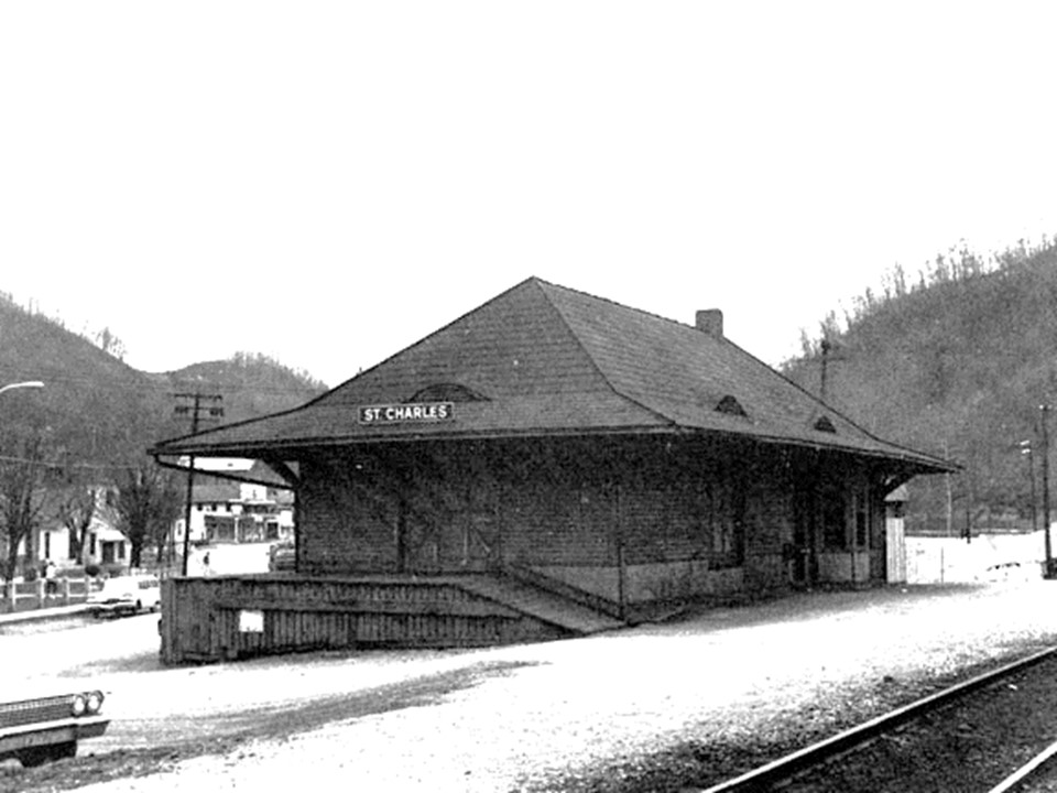
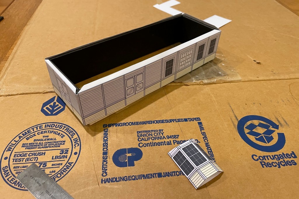
One of the few pictures I’ve found of the St Charles depot–it was darker, but I lightened it to see more of the details (photographer unknown, please tell me if you know so I can give proper credit)
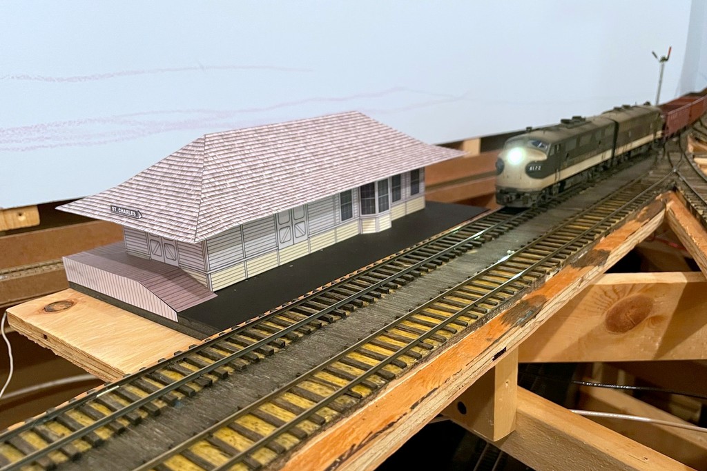
The St Charles depot burned down in the late ’70s, so there are very few photos of it. I worked with a couple of grainy shots and one grainy overhead image to get the basic size and layout. I used scanned plans from other Southern stations to get basic dimensions and features and to serve as a template for building the drawings in PowerPoint. I don’t have the space to model the station full-size, so I aimed for about 90% to scale on the length and about 70% on the width. The toughest part of the drawing was getting the cut angles for the roof right in a flat rendition so I could get the 3D shape correct. It required some trigonometry that made my brain hurt, but in the end I got a double-pitched roof with 22- and 35-degree slopes, pretty close to the drawings of other Southern stations. I omitted the curved roof windows for the mock-up as they would have been a pain and aren’t important to visualizing the scene. The detail like windows and siding is just lines and shapes drawn in PowerPoint, and the roof shingles are a texture I found online. Don’t ask me why the door on the track side of the station is suspended on the wall with no ramp or dock, but as you can see on the prototype photo, it is!
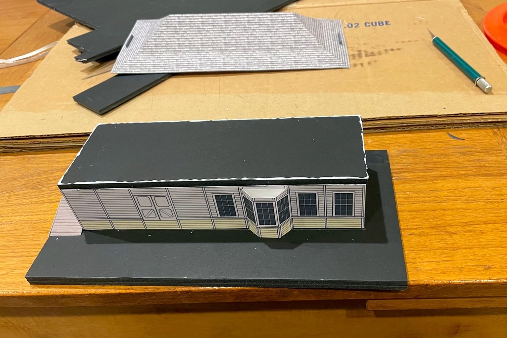
I used 1/4″ foam core to give stiffness to the basic structure
I learned from the Mayflower tipple that using ordinary paper results in the glue bleeding through and staining the color, so I printed this one on heavy paper, almost card-stock and about as thick as my printer would handle. I cut the basic walls out of 1/4″ foam core using the drawings as a template to give it rigidity, but the roof is just the card stock. I built a base and the loading dock on two sides using layers of foam core and covered parts with print outs of boards and vertical siding cut to shape. A couple of tiny “ST CHARLES” signs made from folded paper completed the mock-up. Everything is assembled with basic white glue. After it dried, I set it on a piece of plywood I attached to the sub-roadbed using spacers to level it on all sides–I figure this will make it easier to install the final structure level.
Now that it’s in place, I see that I need to raise the roof probably another 3/16″ which will be easy enough to fix in the final version [update, I raised the roof another 3/16″ as seen in the first photo, and it looks better]. For now, though, it’s great to have something anchoring the scene in St Charles, and I’m sure it will perform many years of dutiful service as I’m very slow. Oh, and if you know what colors the St Charles station was painted (there are clearly two), please leave a comment!
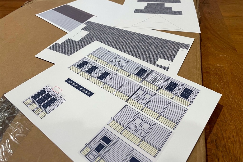
Here is the set of scale drawings flattened and printed on heavy paper
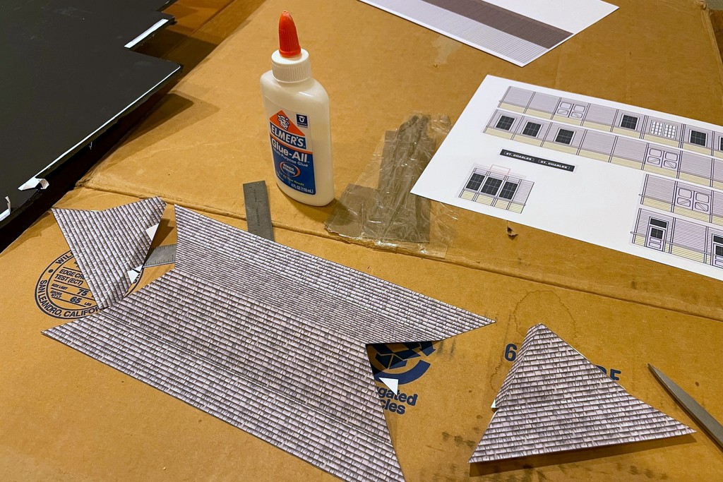
The toughest part of the drawing was getting the angles of the roof right… trigonometry in 3D… my brain hurts, but it worked!
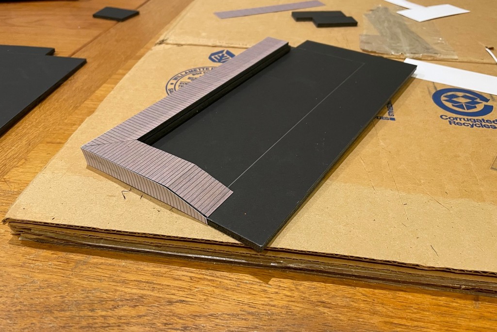
I used 1/4″ foam core to give stiffness to the basic structure
The base and loading dock are made from layers of foam core with paper boards cut and glued to the edges
The original mock-up with the roof too low… didn’t look quite right
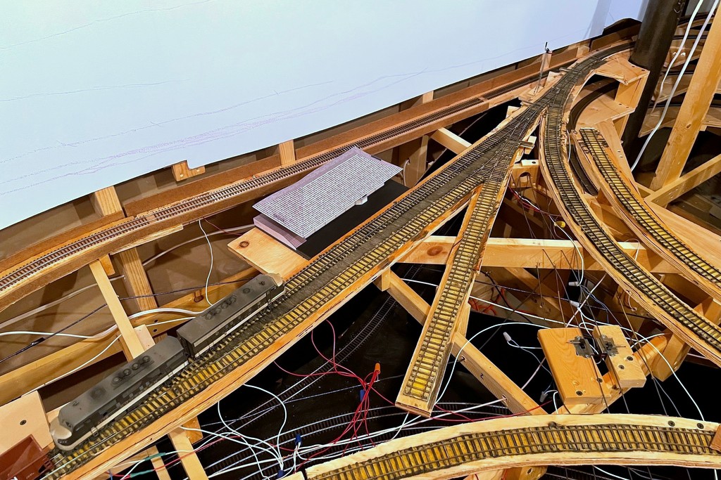
Bird’s eye view of the station scene–the track in the back will be hidden by a hillside behind the station
After letting the mock-up sit for a day, I decided to “raise the roof” to get it closer to prototype. I carefully removed the roof with an X-Acto blade and cut a piece of 1/4″ (really 3/16″) foam core to raise things a bit
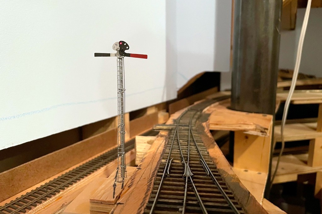
The St Charles local slows to pick up orders from the operator at the St Charles depot
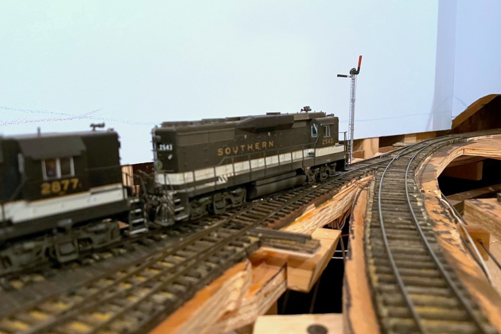
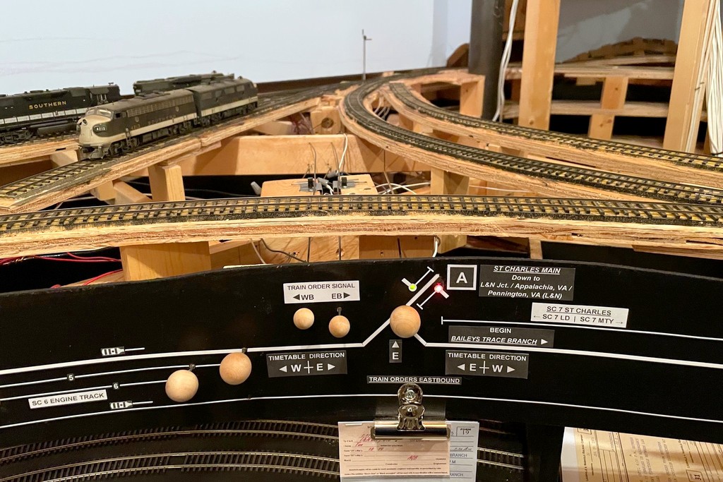
The semaphore in action indicating the St Charles Local has no orders to pick up before proceeding eastward to AppalachiaBlade down and red light indicating both east and westbound trains must stop at the station to sign for orders
I had one major project to complete before completing the scenery base on the lower level, and that was the train order signal in St Charles. I’ve been putting this off for a couple of reasons. First, I’ve never made a full working semaphore before, so I wasn’t sure exactly what I was taking on–the dwarf semaphores I made a while ago gave me a significant head-start, but this was much more complex. Second, I don’t know exactly if the Southern used a semaphore in St Charles – or if they did where it was located – so I was hopeful my procrastination would result some evidence. Alas, I finally just had to bite the bullet and build the thing! Yes, I know there are commercially available semaphore kits, but what would be the fun in that? I’m a glutton for punishment, and I had a bunch of brass stuff laying around, so why not try to scratchbuild one?
I know with 100% certainty that the station in St. Charles had an operator who passed train orders to Southern and L&N crews working the branch. There is both photographic and timetable evidence for this. In the era I model, it was typical for a train order station to have a three-color signal of some sort indicating “red” (stop to sign for orders), “amber” (slow down to pick up orders) or “green” (no orders – proceed), and a three-position semaphore was common. On most stations, the semaphore is built right alongside the station’s office with the control levers inside the station. However, pictures of the St. Charles station clearly do NOT show an adjacent semaphore or any other type of signal. The only thing I can think is that the Baileys Creek Branch to Mayflower cut off the St. Charles main a couple hundred yards geographically south of the station, and train movements on this branch were controlled by the station–perhaps the signal was closer to this junction to allow train crews to see it an heed from both the St. Charles and Baileys Creek Branches. So, that’s what I chose to model!
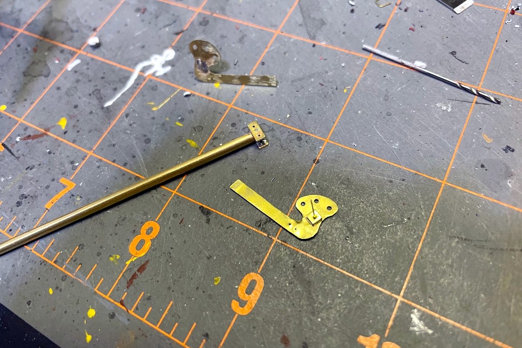
After finishing the semaphore blades, I attached a .015″ brass wire via solder and made a spacer from brass strip folded on itself. I used the same brass strip to make swivel bases for the blades on both sides of the pole
Like my dwarf semaphores controlling access to the coal branches, I wanted the semaphore to be fully operational including lights, blade movement, and fascia-mounted controls. The first job was making some semaphore blades. I did this by making an outline of an upper-quadrant blade in PowerPoint, scaling it to 1:87, and printing it onto a label. After attaching the label to some thin sheet brass, I drilled holes for the lenses, pivot point, and control rod and cut out the blade with scissors, using a file to clean things up. I soldered on the pivot rod, .015″ by bending one end, inserting it through the hole, and soldering it to the blade face. Next I added a small spacer for the blade onto the rod made from a piece of small brass bar bent on itself with a hole drilled through. I painted the blades flat black and insignia red for the blade end. The back of the blade got some silver Sharpie following pictures I’ve seen of other Southern stations. The lenses are just short pieces of fiber optic with one end melted into a round shape using a soldering iron (just hold it near the end of the fiber optic), attached with CA and colored with kids markers.
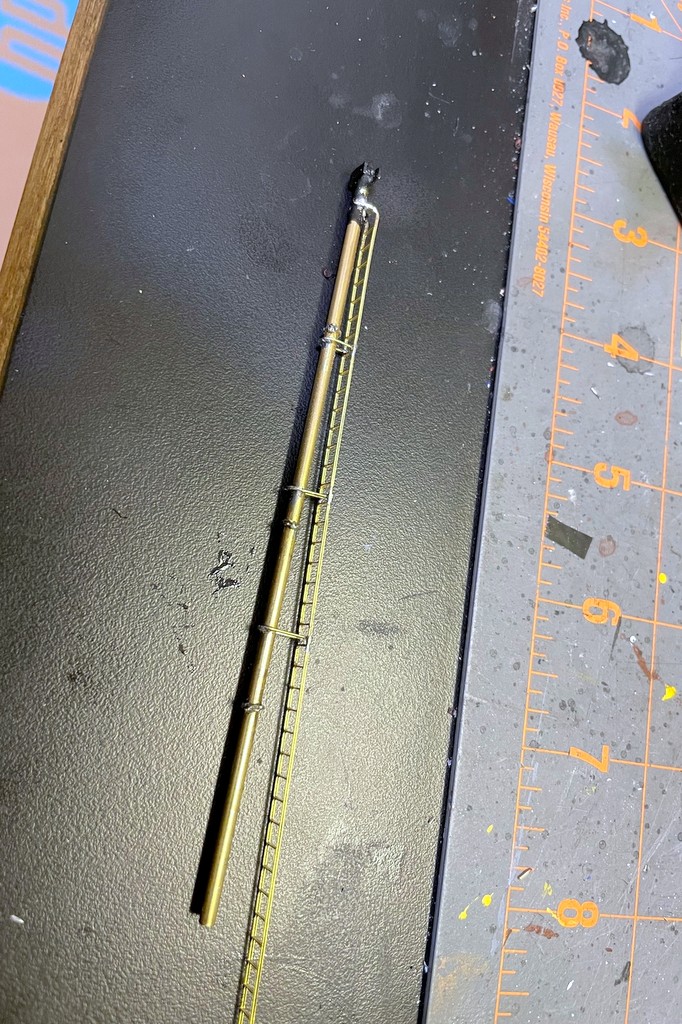
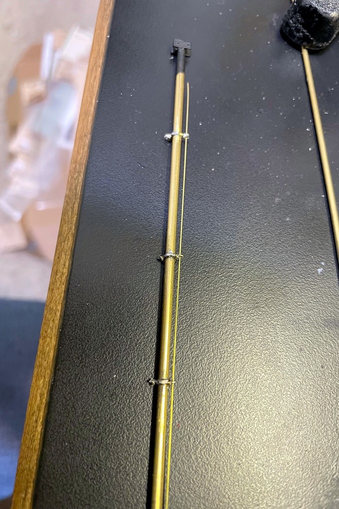
The next step was to add the brass ladder stock and connect it to the mast with U-shaped .015″ brass wire
The mast is a piece of 3/32″ brass tube. I made two mounting plates for the top out of brass bar, filed flat spots onto the tube, and attached them via solder. Next I added some guide loops for the rods that would go from the ground to the blade. I bent something resembling the shape of Saturn out of .015″ brass wire and soldered it tightly around the mast, using a semaphore mast diagram printed to scale as a guide for positioning, three guide loops total. This resulted in two U-shaped loops, one on either side of the mast. I finished the loops by soldering a small piece of wire across each U to make a smaller hole to the outside away from the mast. My soldering skills are not great, so this was a lot of ugly blobs until I took a file and cleaned things up. I added a piece of brass ladder stock by connecting it to the top with solder, bending it, and making U-shaped supports out of .015″ brass wire which I soldered into place in three locations and cleaned up. I painted the mast assembly flat black and then used a combination of silver Sharpie and silver paint to finish it.
Now I was ready to put the blades onto the mast. I fashioned some control rods from .015″ steel music wire, inserted them into the blade holes, and ran them down the guide loops on each side. After inserting the blade pivots into the mounting plate, I bent the brass rod 90 degrees to hold each blade in place while allowing it to pivot freely. I made the base from scraps of plywood (see pictures) and drilled a 3/32″ hole for the mast, two adjacent 1/16″ holes which I lined with 1/16″ brass tubing for the control rods, and a larger hole for the ladder to slide into. I press fit the mast into the holes with the rods going through their brass tubes. Then I ran a piece of fiber optic cable down the tube. I first tried to file one end of the fiber optic at an angle to get it to shine through the blade lenses, but this didn’t work well. I ended up holding the fiber optic over a spare piece of 3/32″ brass tube which I heated with a soldering iron. When the tube got hot, the fiber optic bent itself over the tube in a perfect curve which still conducted light well. A little more heat to make a rounded lens at the end, and I had my “light” for the blades.
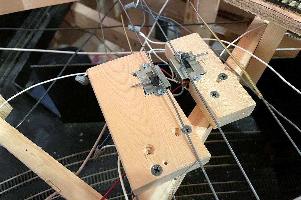
Here are the mechanisms made from 3-way slide switches. Not only do the switches route power to the bi-color LEDs, it also connects the lever to the signal mechanically and provides the detents for movement
I wanted to use .062″ steel music wire (the same stuff I use for manual turnout controls) for the fascia-mounted control rods, so I crafted two triangular levers out of thick styrene hinged at one corner to convert the horizontal control rod movement into vertical movement for the blade control rods. I covered this in some detail with the dwarf semaphores, so I won’t cover it again here. With the mechanism in place, I mounted the base and semaphore assembly in place on the layout. Next, I worked on the control rods made from 36″ pieces of .062″ steel music wire. Where they would cross through benchwork, I drilled 2/32″ holes and lined them with brass tubing. I was able to get a pretty good bend in the control rod without it kinking this way.
Here’s the finished semaphore from levers and lights to the blades in the background
The heart of the control rod mechanism is a 3-way slide switch. I bought a handful of these for the dwarf semaphores because of their longer throw, but it turns out they were exactly what I needed to control both the throw and the lights for the full semaphore. I’m using 2-lead, bi-color red/green LEDs for the lights. Controlling the red and green is easy enough with DC and crossing the +/- leads on two of the poles on the switch to get the red and green on the end throws of the switch. For the amber, I wanted to use the AC current from my track power. It took a bit of thinking through the use of the 16 leads (it’s a 4-pole slide) to figure out how to route both AC and DC power to the same LED without ever crossing the streams, but the arrangement seen hand-drawn on my cheat sheet (see gallery below) works well. I secured the rods to the semaphore to the slide switch by bending them 90 degrees and inserting them into a hole drilled through the switch control. A second rod inserted through a second hole in the switch control was run through a piece of 3/32″ brass tubing to the front of the fascia where I capped it off with a wood ball (smaller than the ones I use for switch controls so operators can tell the difference).
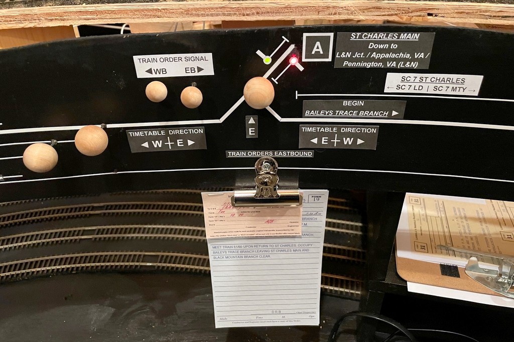
The final step was to run LEDs from both switch mechanisms to the fascia where I used stick-on letters and graphic tape to make a little drawing of a semaphore in each direction alongside the track diagram–the operators can look on the fascia to see the color indication if they don’t want to use (or don’t understand) the blade positions on the layout. Finally, I added a second clip to hold orders under the fascia so that the old clip is now “train orders westbound” and the new clip is “train orders eastbound.” So far I’m really happy with how the semaphore looks and now it operates, and it was really fun to build. I know it will add yet another aspect of prototypical operations to the layout as crews now have to read signals to see whether or not they need to pick up orders.
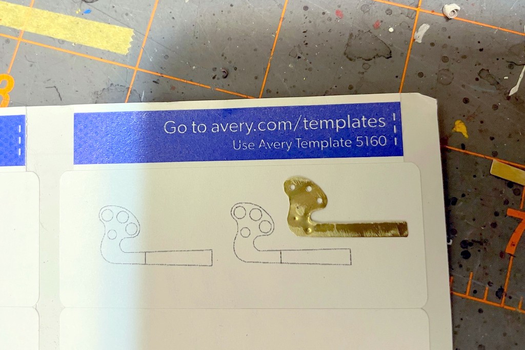
I made a diagram of a semaphore blade in Microsoft PowerPoint then printed it in HO scale onto a label. This made it easy to attach it to the sheet brass, drill holes, and cut it out with scissors
After finishing the semaphore blades, I attached a .015″ brass wire via solder and made a spacer from brass strip folded on itself. I used the same brass strip to make swivel bases for the blades on both sides of the pole
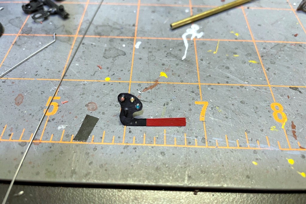
One of the finished blades painted black and red with no stripe per Southern custom. The lenses are short pieces of fiber optic with one end melted round by holding it close to a soldering iron. The color is just marker
I made guides for the blade control rods using .015″ brass wire bent into a “flat Saturn” shape around the mast. The control rod is .015″ steel music wire
The next step was to add the brass ladder stock and connect it to the mast with U-shaped .015″ brass wire
The base plate is simple. Under the signal is a second layer of plywood to get the signal to track level. Holes for the mast, rod guides and ladder are in the middle (the right-hand holes are mistakes). The plywood fin will support the levers to connect the manual control rods to the rods going up to the blades
Here’s where the lever rods meet the rods going up to the blades. The multiple holes in the styrene allow the rod to be repositioned for more or less throw (I ended up using the top hole on both to get more throw)
Blade down and red light indicating both east and westbound trains must stop at the station to sign for orders
Blade halfway and amber light indicating the eastbound train should slow to pick up orders (handed up by the operator) but doesn’t need to stop and sign for them
Blade up and green light indicating no orders for the eastbound train
Here’s the little cheat sheet I made up. I scaled the blueprint to HO and used the sheet to plot my throw and my wiring for the 3-way slide switch
This is the finished wiring of the 3-way slide switch. The ends connect to DC for the red and green colors of the bi-color LED. The middle attaches to AC (DCC track power) for the amber (rapidly flickering red and green)
Here are the mechanisms made from 3-way slide switches. Not only do the switches route power to the bi-color LEDs, it also connects the lever to the signal mechanically and provides the detents for movement
Here’s the fascia end of the semaphore including levers (WB in, EB out), indicator lights along the track diagram, and the clip for the orders which necessitate the signal
Here’s the finished semaphore from levers and lights to the blades in the background
The semaphore in action indicating the St Charles Local has no orders to pick up before proceeding eastward to Appalachia
The first scenery forms are in place at Mayflower using Howard Zane’s paper shell method
So there are two reasons why I’ve been working on so many models lately. First, I enjoy building models. Secondly, I’ll admit that I’d hit a major mental block with the layout’s progress because I needed to work on the basic scenery for the lower deck before adding the benchwork for the upper deck. I could retrofit the scenery, but I figured it was worth it to add it now to save myself about 260 lumps on the head trying to install it under the upper-deck benchwork. This last week I finally got up enough gumption to jump into the deep end and start the scenery!
The first step is to draw out the line where the scenery meets the backdrop and glue a cardboard strip along the line
Ever since I read his article in the Jan 2007 Railroad Model Craftsman, I knew I wanted to use Howard Zane’s “paper shell” scenery technique. For mountainous ground that’s mostly going to be covered by trees and the occasional rock casting, this method is extremely simple and uses easy-to-find and cheap materials including cardboard, hot glue, red rosin paper (available for under $20 for a 3′ x 167′ roll at home improvement stores), and white glue. I won’t go into his whole technique, but you can see from the photos that it’s essentially outlining the hills on the backdrop with a cardboard strip, building a lattice of the basic landform from strips of cardboard, and covering the lattice with small patches of rosin paper. The next step (which I haven’t started yet) is to cover everything with a thick layer of white glue to smooth it out and give it stiffness.
Step 2 is to make a lattice of cardboard strips. I bent them and softened them before installing them with hot glue to get more natural bends
I’m starting with Mayflower and working around to St. Charles. Some would recommend a much steeper terrain so the majority of the background is hills and trees, but I’ve opted to go with a more natural angle between 30-50 degrees slope. This means my backdrops will need to be painted really well since the transition from scenery to backdrop will be very visible. If you look closely you can see where I’ve drawn in the ridge line near the top of the backdrop. I don’t know how to paint yet, so what could go wrong? We’ll see how that goes soon enough!
So far this has been a time-consuming but enjoyable project, and I’m very happy with the paper shell method. I’m learning little tricks as I go which will make it go faster as I gain more experience, but it’s great to start seeing things take a shape other than plywood and dimensional lumber!
Step 3 is to hot glue small sections of red rosin paper to the cardboard lattice