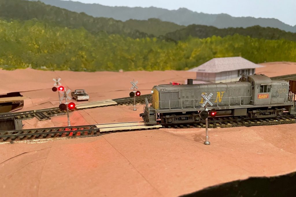
Many of the grade crossings on the St Charles Branch didn’t have flashing signals and were protected by flagmen or fusees (see how I simulate fusees here), but a few of the more prominent crossings were protected by automatic flashing signals and bells. One of those crossings is Bonny Blue Road which crossed two legs of the wye in St Charles. I was looking for a way to make these signals work automatically with nothing required of the crews (beyond sounding the horn for the crossing) and no hardware needed on any rolling stock. I quickly settled on using IR sensors mounted near the tracks to trigger the circuits required for the crossing. While many of the major manufacturers of railroad electronics offer circuits for flashers and for triggering based on sensors, there seemed to be a lack of good, simple options for the sensors. So I did what many of us do when we’re looking for something–I turned to eBay.
I found a lot of products for flashing crossing signals, but one it particular caught my eye. A company called “WeHonest” was offering what looked to be decent looking LED signals that came with a flashing circuit for a very reasonable price. Being a little suspect of a foreign company calling itself “WeHonest,” I needed four signals, so I ordered a couple sets and hoped for the best. I ordered the signals with two heads instead of four (front and back) because my signals would only been seen from one direction, and the ones with four heads looked too thick front-to-back (I plan to add dummy heads on the back later). When they arrived a couple weeks later, I was impressed with the quality for the price. The lettering is easily readable, the construction is mostly metal, and the size and shape are good for HO scale. I had to clean up some areas of the metal crossbucks, and some of the silver paint flaked off, but these were easy fixes. I initially hooked up the flashing circuit to a pushbutton on the fascia, and the flashing circuit worked flawlessly and controlled all four signals in a synchronized manner.
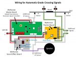
The signal piece was solved, so now I needed a way to automatically control them. My confidence in “WeHonest” was bolstered, so I explored their options. They offer a “model train detector automatic signal controller crossing system trigger etc” (also called a “master board”) which shows a diagram of how it can be configured to trigger a grade crossing flashing circuit using simple, single-unit IR sensors that don’t require a broken path. I also needed a circuit that could support four sensors due to the tracks that would trigger this grade crossing, and while the board only supports two sensors, their diagrams show that you can connect more sensors via separately available splitter cables. They also offer a sound effect circuit with multiple grade crossing signal bells (and a rooster). I ordered a master board, sound effect board, two splitters, and some additional IR sensors.
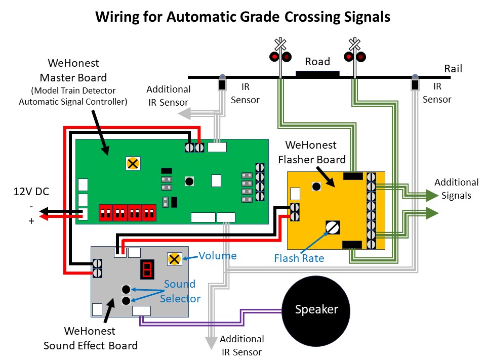
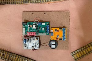
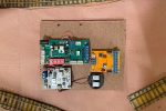
The documentation you see on eBay is all you get, so it took some studying and tinkering to set things up, but it wasn’t difficult. The basic idea is the master board is connected to 12V DC and the IR sensors. The sound effect board and flasher circuit are daisy chained off the 12V DC “output” side of the master board which is only live when the IR sensors are triggered. The only surprise on wiring was there are no normal contact screws for the 12V DC input, only a plug for an adapter and a specific connector type (both of which are sold separately). I found a plug off an old RC helicopter I disassembled years ago that did the trick. I mounted all three circuits and the speaker on a piece of masonite to keep the wiring tight and organized. Rather than use the supplied speaker, I attached a pair of baffled cube speakers I had pulled out of a locomotive when I replaced it with a Scale Sound System speaker.
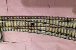
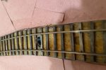
I installed the IR sensors between the rails and ties as the company indicates in the pictures. When anything passes over it within a couple inches, the IR sensor is triggered. There is no documentation on how the sensor works, but it has two elements, a blue dome and a black dome. I can only speculate that it transmits IR from one dome and receives reflected IR in the other dome. When I hooked everything up, it worked great… with two IR sensors plugged into the two separate sensor inputs on the master board. When I tried to use all four IR sensors, it would trigger the circuit no matter what I did even if nothing was present. I noticed some sensors were more sensitive than others, so I experimented with different placements and combos and even the positioning of the elements within the sensor. Unfortunately, I destroyed one of my sensors in the process, but thankfully they’re inexpensive, and I found the WeHonest customer service to be very responsive and helpful!
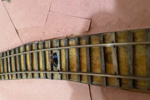
When my replacement sensors arrived, they did the exact same thing as before. Two sensors worked fine, four sensors triggered the circuit even with nothing present. I really liked the overall operation of these circuits, so I kept experimenting to see what might work. I speculated that the circuit detects based on a threshold of received IR energy–with one sensor, the ambient IR was low enough to stay below the threshold, but with two sensors, the ambient IR increased above the threshold to make it appear a train was present. I found that if I covered a portion of the black domed element on some of the IR sensors, it would keep the circuit from triggering but would still trigger if a train passed. After playing around, I found covering about 60% of the black element of all IR sensors with a small piece of electrical tape made everything work as intended.
Now that I’ve worked out the kinks, I’m very happy with the crossing! I’m able to control the sensor sensitivity via the electrical tape, I can control the flash rate of the LEDs via a dial on the flasher circuit, I can select the bell sound from one of several good options on the sound effect circuit, and all of this works automatically with no actions needed from the crew. I have two more flashing grade crossings to go on the upper level, and I’m satisfied enough that I’ve already ordered the parts to replicate this installation on those crossings.


Dan
Nice job. I like the video Do you have a Youtube channel for the St Chares Branch?
Bill
Well, I do now! More on that in a future post once everything’s set up