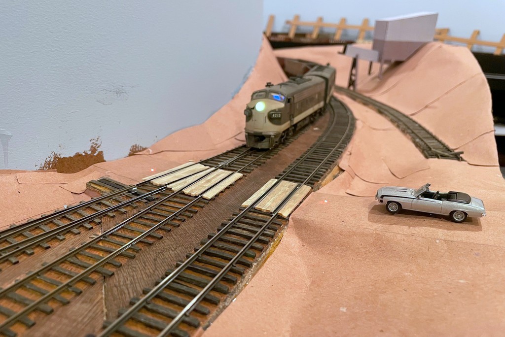
I enjoy trying to copy every element of prototype railroading I can… as long as there’s at least an element of fun in it. When I saw this short video showing a Western Maryland crew dropping fusees (pronounced “fyoozees”) to protect a grade crossing, I started thinking about how I might model this. Fusees are used by railroads for many purposes including dropping them on tracks to warning following trains of their presence–because of this purpose, fusees are designed to burn for a set time, commonly 10 minutes. Fusees can also used to protect grade crossings that don’t have flashing lights like the one in the WM video, especially when it’s dark or posting a flagman wouldn’t be practical or safe. Since I want to model nighttime ops, and I haven’t made any HO scale flagmen to post yet, I decided I wanted some simulated fusees to protect the handful of crossings I have on the layout.
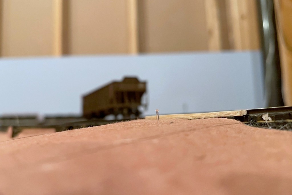
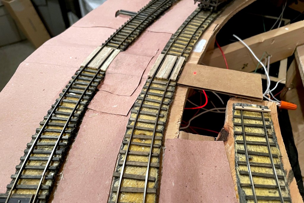
My first attempt was pretty simple and economical, just two fiber optic cables embedded into the “road” (it’s just paper and cardboard at this point) on either side of the grade crossing routed to a bi-color LED that I connected to the DCC track bus (creates a reddish orange glow) and a simple SPST push-button switch. To keep the fiber optic cable from falling through the road, I melted the end into a mushroom shape by holding it near a hot soldering iron. The other ends were taped together and inserted into a piece of shrink tubing around the LED. It was functional enough to protect the crossing, but I really wanted a way to 1) put the fusees on a timer, and 2) make them look a little more realistic.
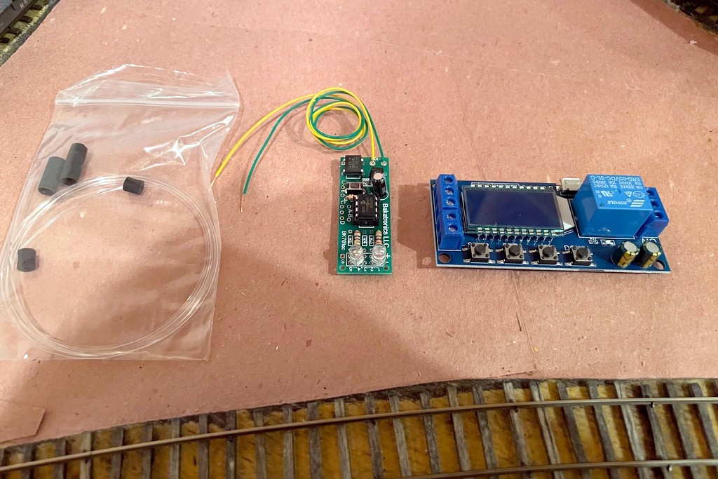
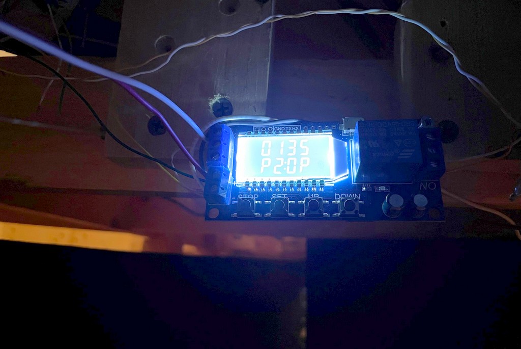
The timer issue was solved by searching Amazon and looking at a lot of different timing circuits. I finally settled on this one, though it’s probably overkill. I like it because you can choose one of several timing modes (fun to play with for other projects), you can set the timer for however long you want to keep the relay “on,” and you can easily see the timing settings on the display. To make them more realistic, I started with an internet search for “model railroad fusee,” and after chasing through some links in model railroad boards, I discover the Bakatronics BK-111 “Simulated Flares / Fusees Kit.” It looked promising, especially since it’s designed to power two fusees that “light” and extinguish several seconds apart (like one person is walking a short distance between lighting them, just like a grade crossing). I ordered two just to make sure it would work, and I was not disappointed! When activated, they “light” at different times, flicker independently for a while, then the first one goes out, then the second with a nice slowly diminishing burn out… really cool looking!
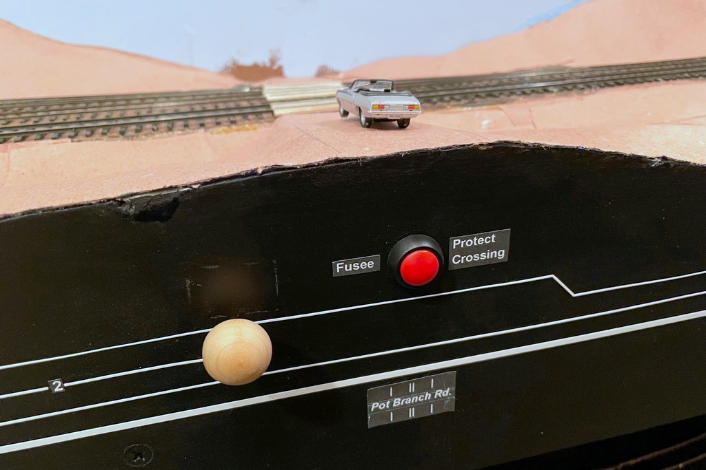
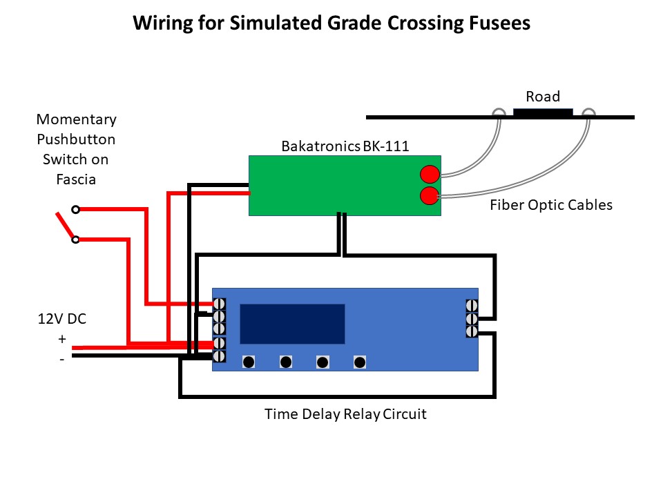
The Bakatronics fusee circuit is designed to work with either a momentary switch (stays on for about 30 seconds) or an on/off switch (stays on as long as the switch is closed). Instead, I wired the fusee circuit to the timer circuit so I could set the time the fusees stay lit exactly, and all the operator has to do is push a button once. I use a 4:1 fast clock, so a 10-minute burn should last about 2.5 minutes / 150 sec. The Bakatronics circuit add some time on its own, so I found a setting of 135 sec on the timer keeps the fusees lite for about 10 scale minutes, and like the prototype, the crew only needs to worry about whether or not to put down another set of fusees (push the button again) if the first set “burn out.” Both the timer circuit and fusee circuit run off a ~12V DC bus I have running around the fascia, previously to power semaphore lights. Here’s a video of the fusee in action…
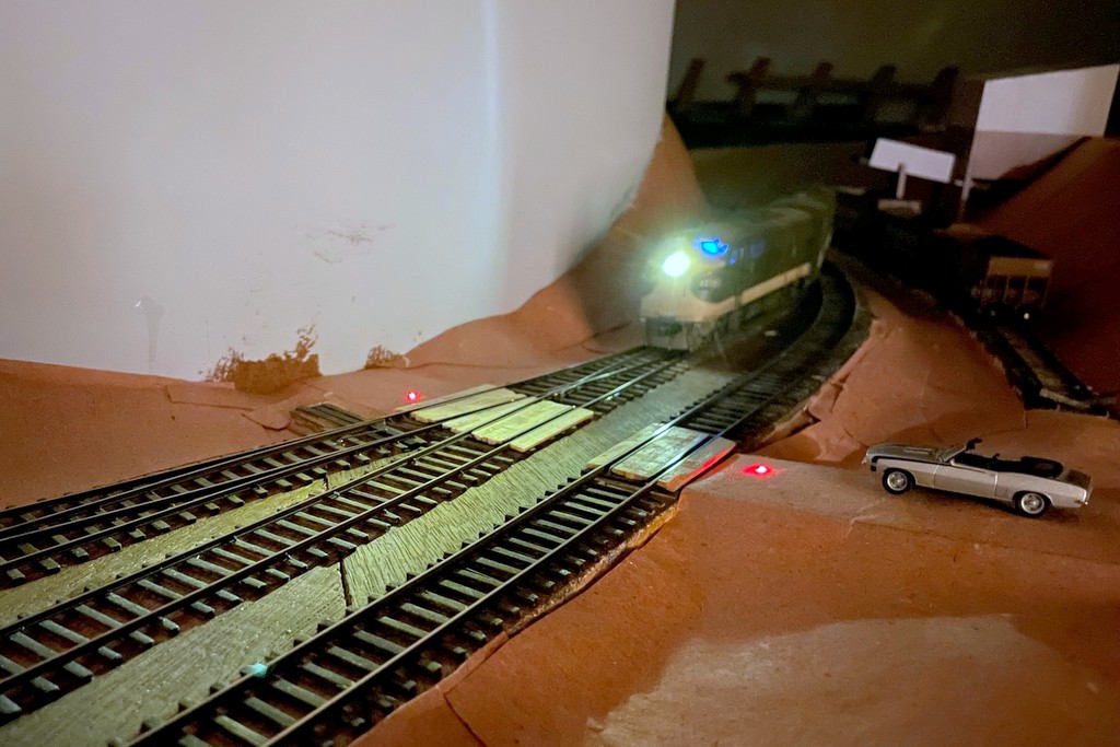
We used these on my last operating session, and I thought they added a neat bit of prototype thinking for the crews–we had to think about protecting the crossings while moving the trains, and the flickering fusees gave a visual representation of the action taken. I can’t wait to try them at night when I’ve got the final lighting installed!
Dan
Nice job. Loved the video. Now we know we can expect a video of a mine run switching Mayflower.
Bill Michael