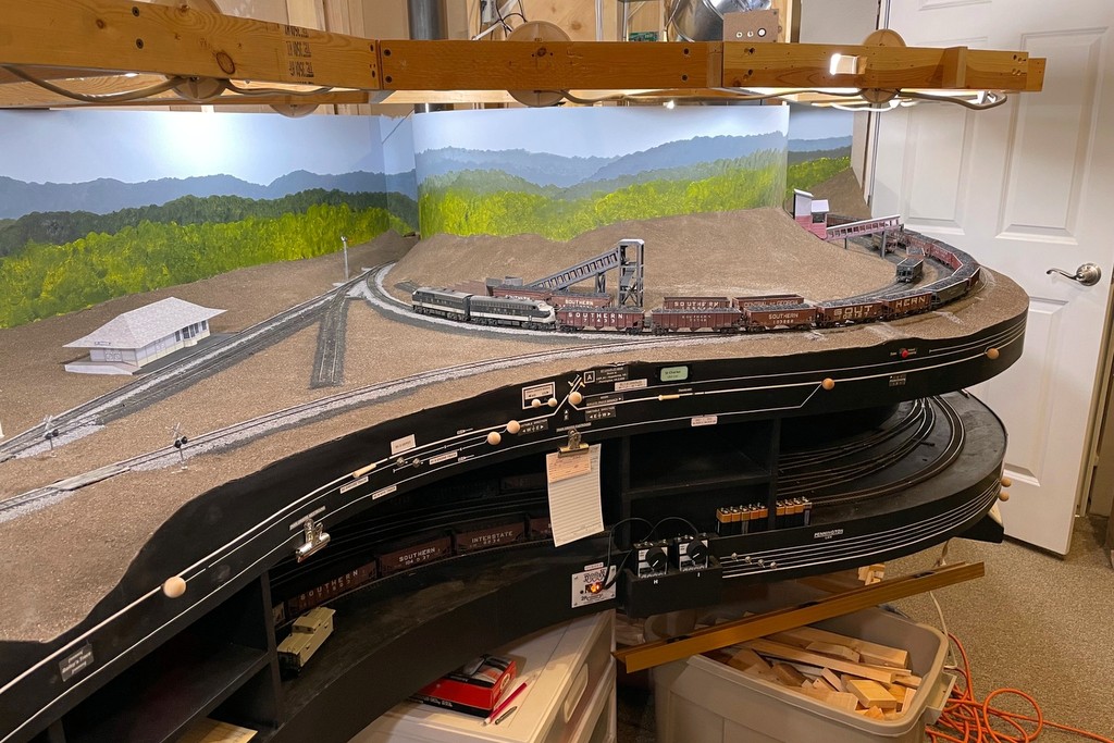
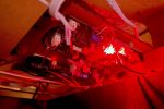
The first layout lights are in! Here’s the “cool white” that I like for daytime
While my light is nowhere near as impressive as God’s light in Genesis, it still makes me glad to see a little more light on the trains in the basement. Now that I’ve got some upper-deck benchwork in, it opened the way to try out the layout lighting I’ve been wanting to do for a while. I’ve looked into LED strings and other bundled lights, but in the end, I’ve settled on using individual multi-color LED “smart lights” I can control with my phone. It’s not the cheapest solution (about $7 a bulb, and my layout needs 40), but it’s bright, and they’re customizable for a dizzying array of colors and brightness!
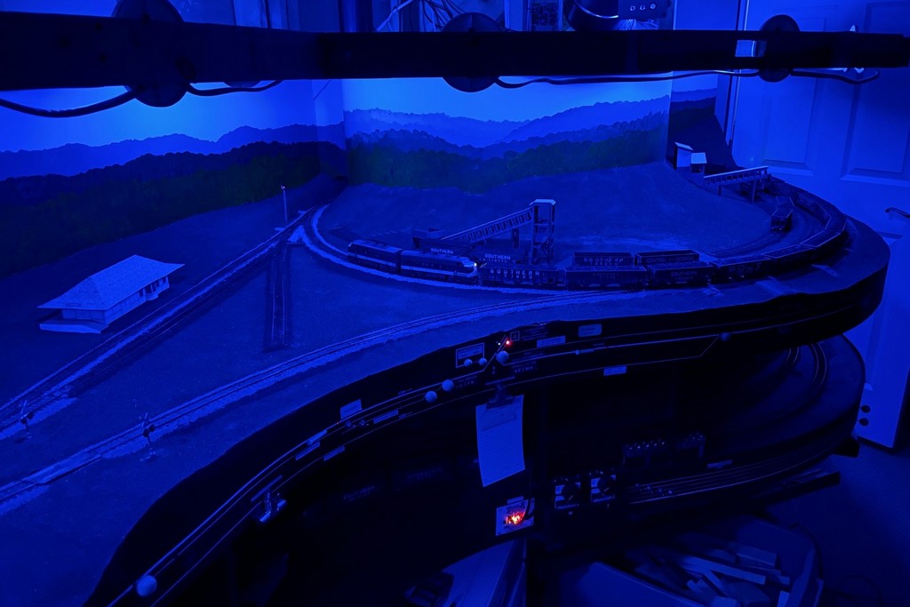
This is a more modern evolution of the lighting on my last layout which used cheap plastic fixtures and compact 40W lightbulbs. I was able to recycle the fixtures and wiring for this project, but the technology is so much better than my previous little analog dimmer. Not only are the LEDs brighter, but they run cooler, only use 9W each, and I can get a nice “cool white” that looks a lot more like sunlight than incandescent lights. I was also able to play around with the colors and dimmer, and a wide range of effects are possible including a nice moonlit night and a warm sunrise/sunset. It’s also easy to “group” them so one command changes all the bulbs simultaneously.
The dimmable, multi-color LEDs can give a lot of different moods like this “moonlit night”
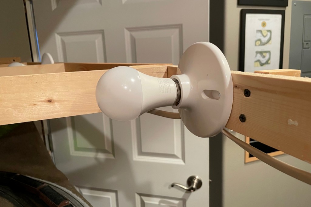
I’ll keep playing with them to try to mitigate the glare spots and shadows. I’m also going to figure out a way to automate going from nighttime to sunrise to day–I’m sure it’s possible with all the Smart Home controls out there now. One thing I hadn’t counted on is the lit portion of the bulb is about 2″ further out from the fixture than the old incandescents. For now that’s creating more shadow along the front of the layout than I’d like. When I put the valance in for the upper deck, I’m inclined to move it out over the aisle a few inches to try to improve this, and I might mount a few of these in the overhead fixtures as well. For now, I’m calling this experiment with 8 bulbs a success, so now I’ve ordered more to keep working around the rest of the layout.
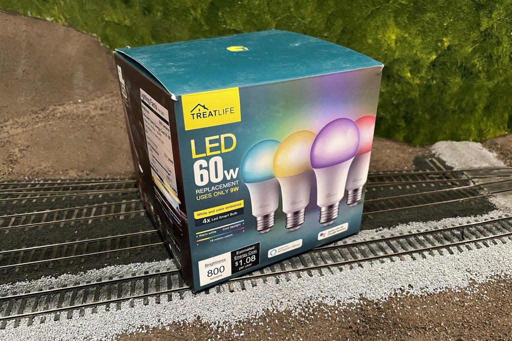
The fixtures for the lighting are simple plastic screw-in basesHere’s what I’m using, TreatLife 60W equivalent (9W actual) multi-color LED smart lights
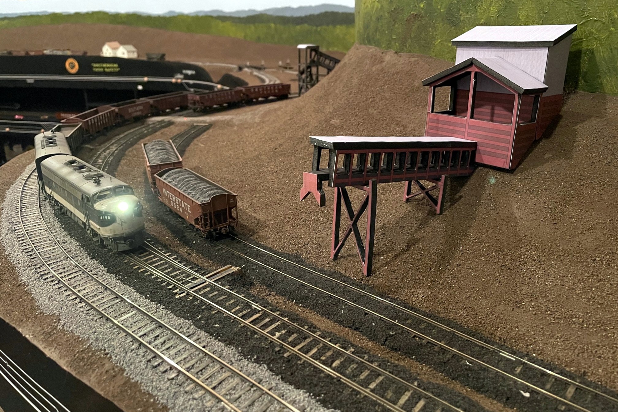
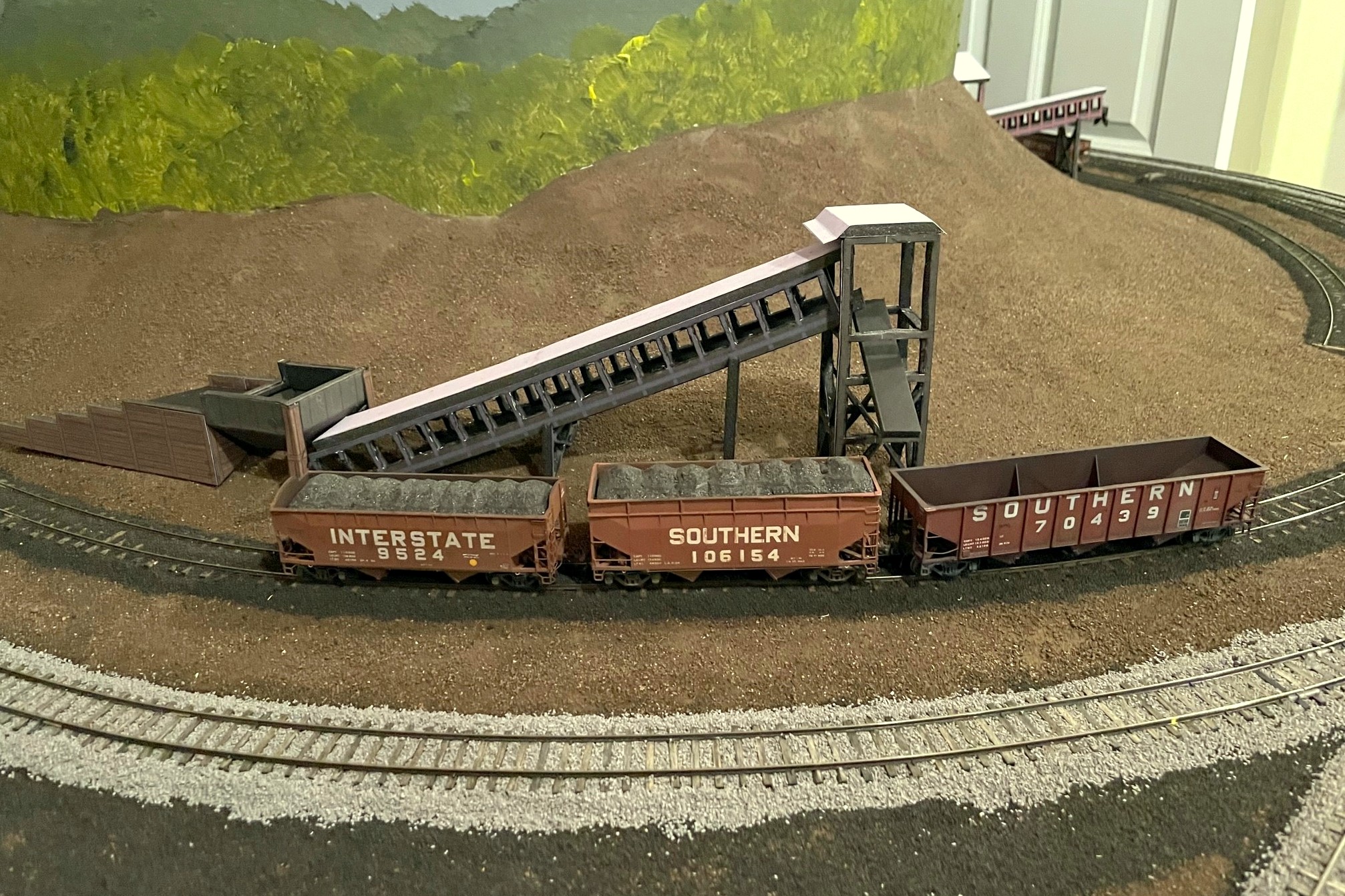
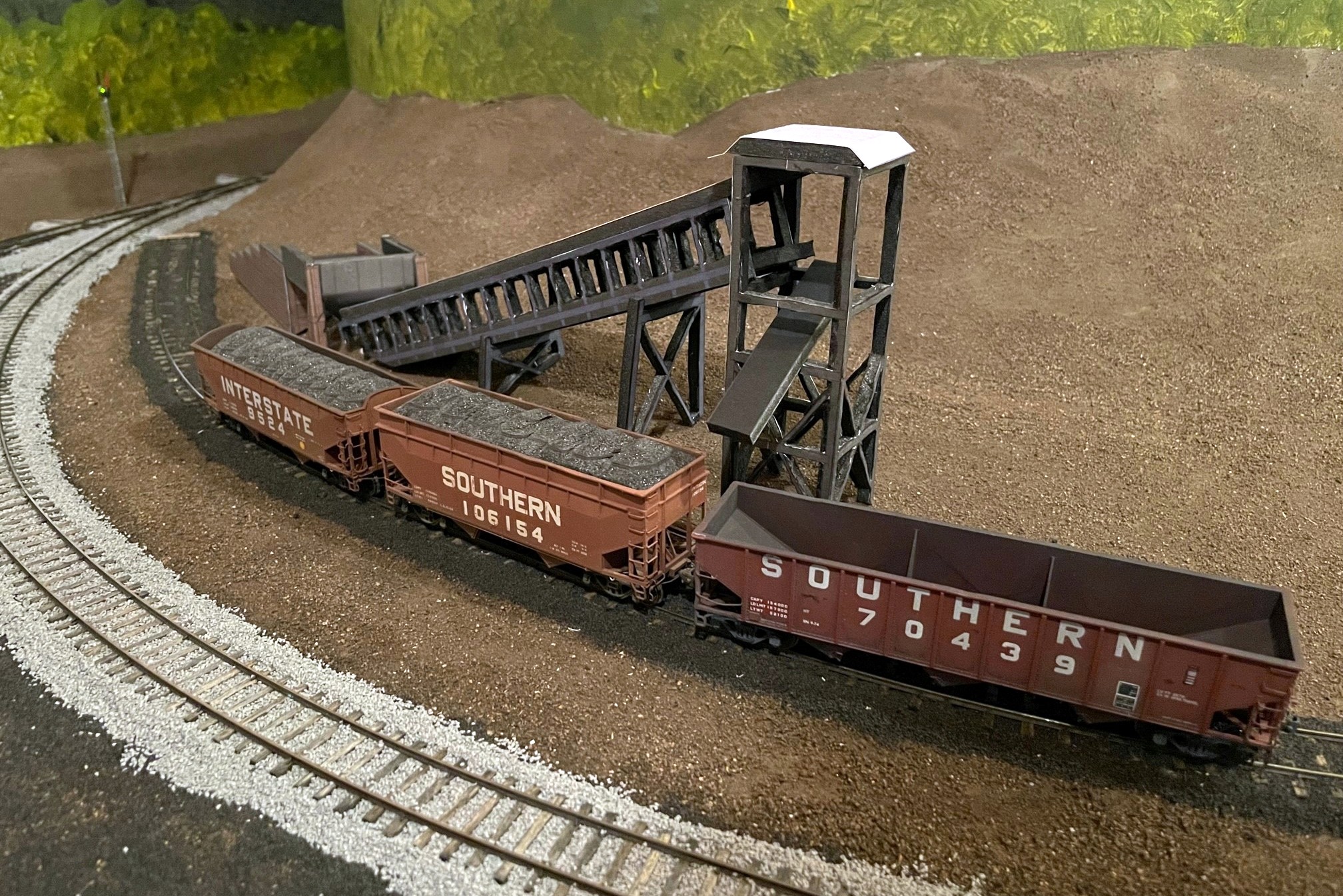
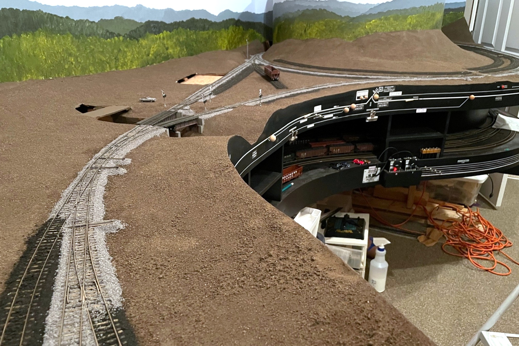
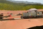
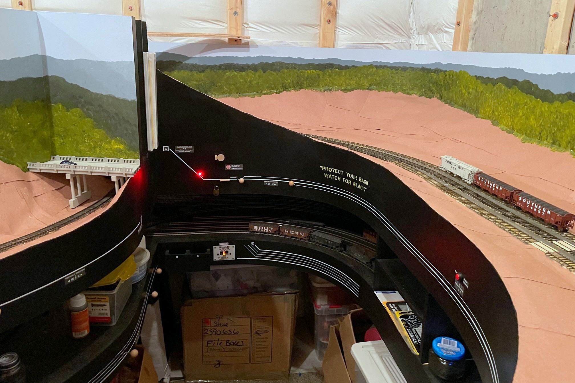
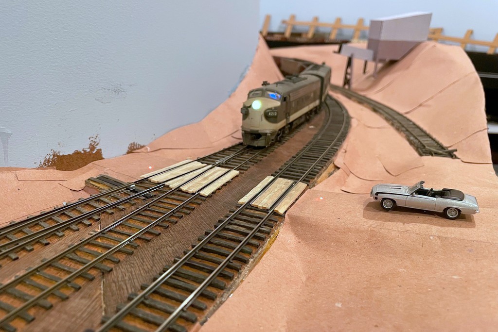
Here’s the full mocked-up scene with the St Charles Switcher preparing to swap empties for loads at the JAD Turner loader–the St Charles loader can be seen just around the hillside
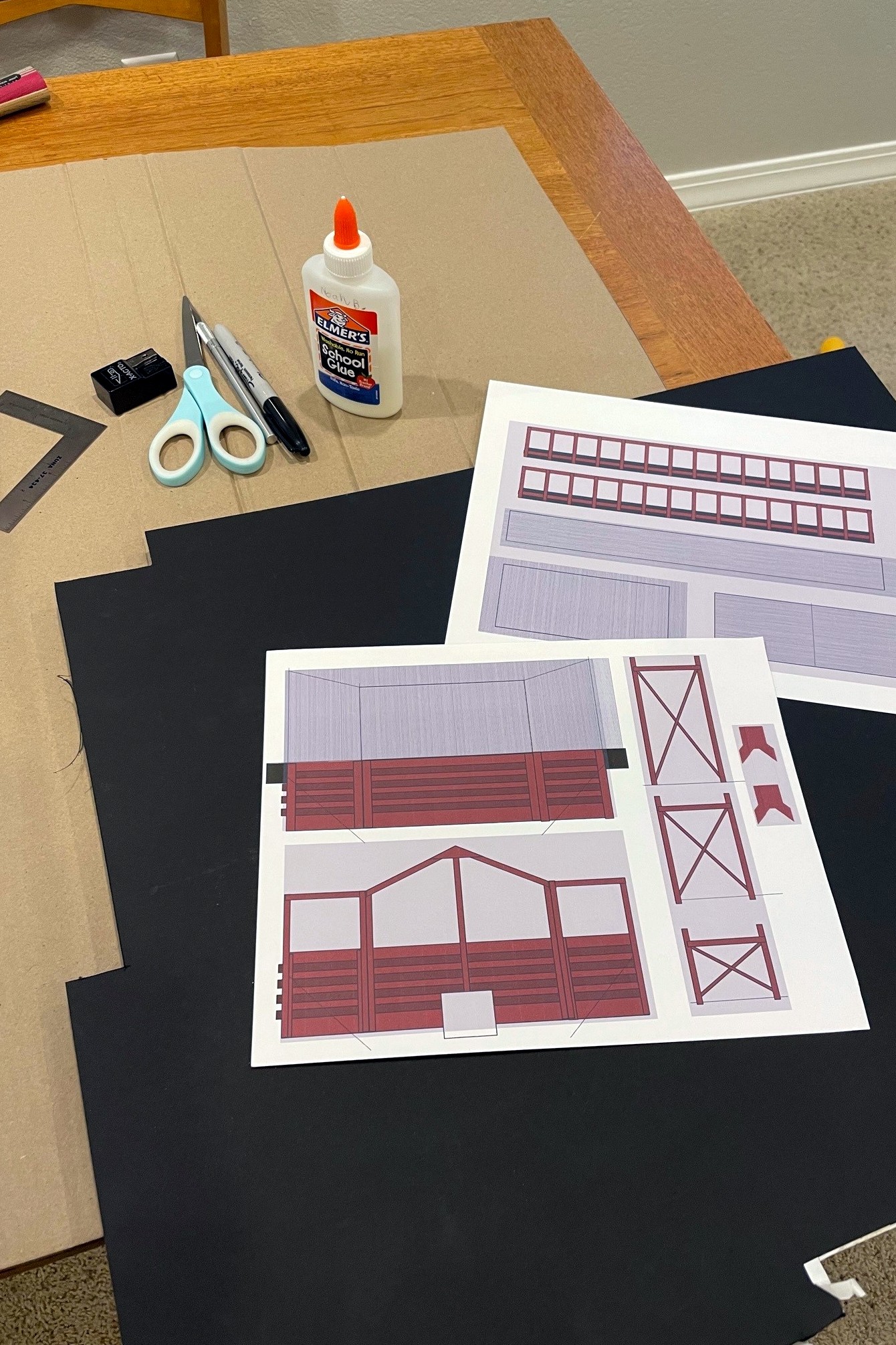
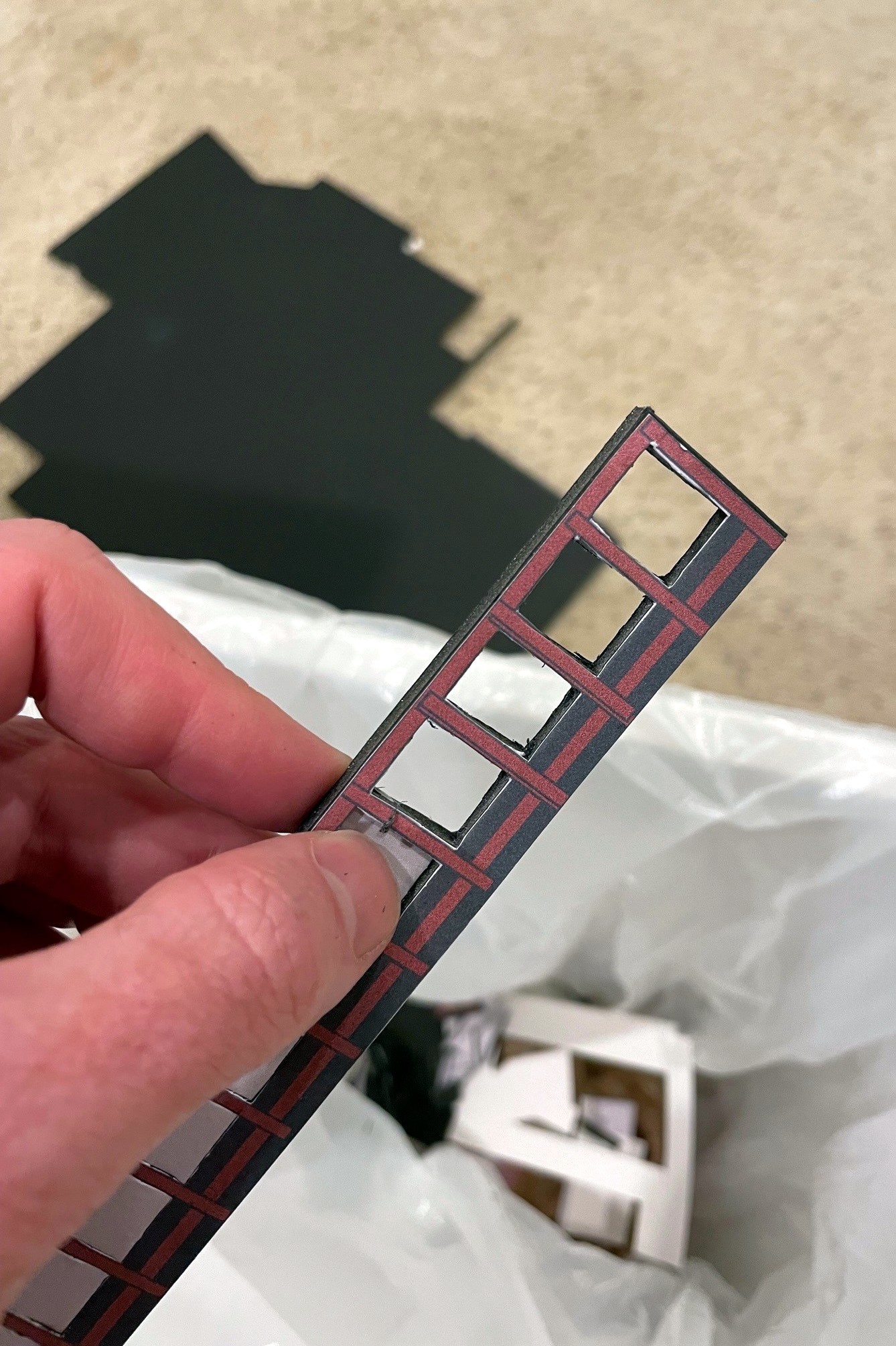
As I’ve discussed previously, I like to build mock-ups out of foam core and paper of the larger structures on the layout that I will eventually scratchbuild. This serves three purposes. First, it gives me an opportunity to create a line-drawing / blueprint and make sure the drawing works before cutting more expensive materials. Second, it allows me to visualize a scene and make adjustments before I build the permanent structure. And third, it gives me a good stand-in on the layout until I can build the real one–something that makes operations a lot more fun than imagining there’s a big structure where you’re switching! For this third reason, I put a little extra effort into the drawings to give them some color and texture. I’ve covered the techniques before, so I won’t repeat them here.
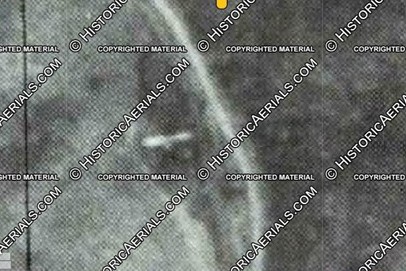
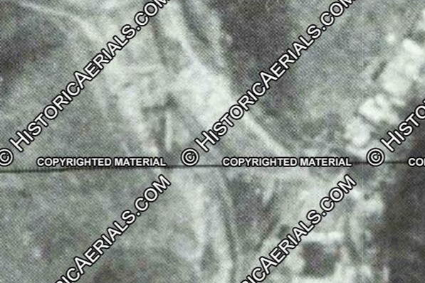
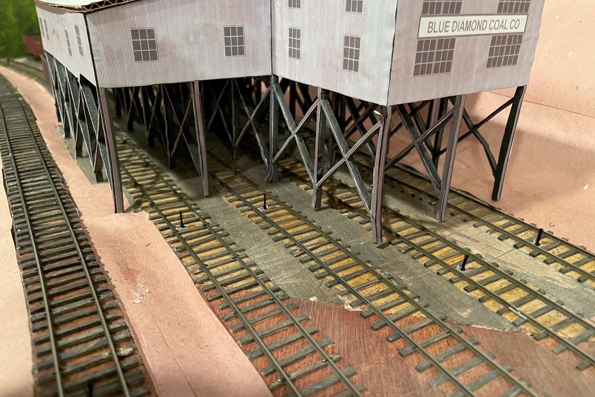
This project involved the two “truck dump” tipples that were built in the late ’70s (as far as I can tell) near St Charles, VA. One is known as JAD Turner, and it’s probably still standing today. The other sat on the wye at St Charles for just a few years–I don’t know it’s name, so I’m just calling it the St Charles loader (super original, I know…). What made this project challenging is I didn’t have any good photos of the loader configuration I needed to model. JAD Turner was modified over the years with a second conveyor and second empty track, but the earliest photo I have of it (a grainy aerial from 1981) clearly shows only a single conveyor. I’m modeling it as if it’s the same tipple but with fewer added parts, so I took the dump shed / crusher section of the current loader along with a single conveyor and came up with this design that looks reasonably close to the aerial.
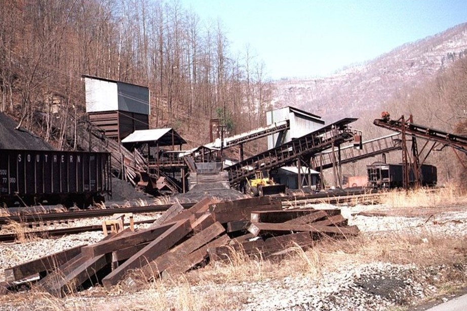
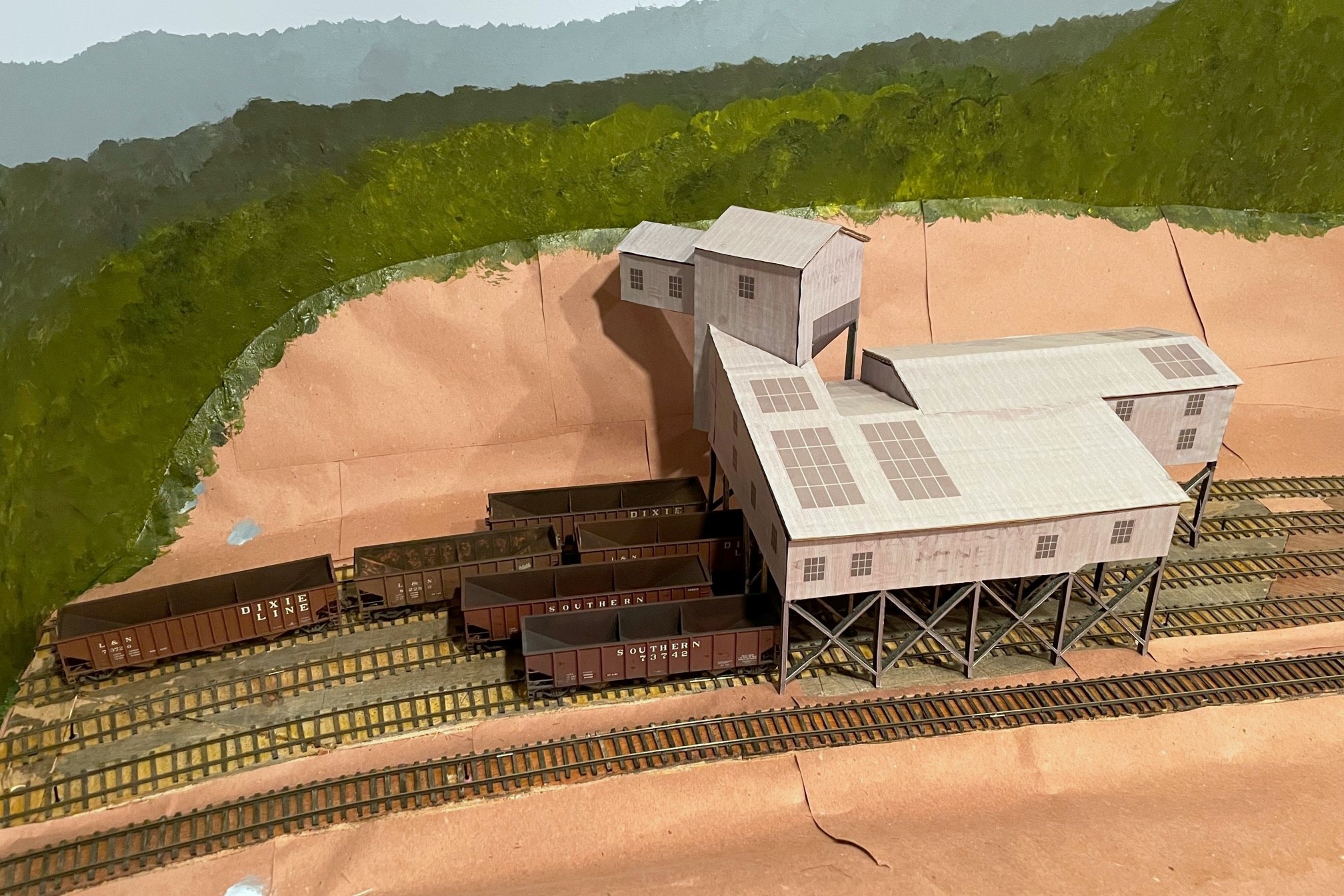
Here’s the JAD Turner loader near St Charles in the late ’90s with additional chutes added, but I modeled the core dump shed, crusher, and one of the conveyors (Robby Vaughn photo)Here’s the finished JAD Turner loader mock-up complete with a little double chute over the rails
St Charles was a little more challenging as the ONLY photo I have is a grainy aerial from 1981 showing what looks like a pile of coal, a conveyor (maybe two), and what looks like a dump ramp but no shed. I didn’t have to look far to find something close. Just up the road between St Charles and Mayflower was a loader known as “Southwest” which had a similar dump and conveyor arrangement. Southwest was built after my era, so I won’t have to have two similar looking loaders on the layout. Who knows, perhaps they moved the loader from St Charles up to Southwest? That’s my story until someone proves otherwise…
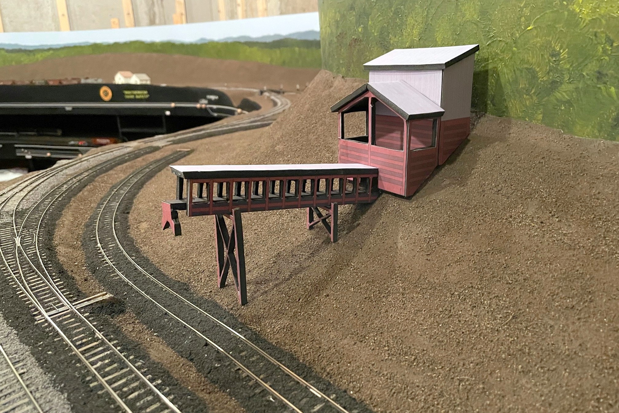
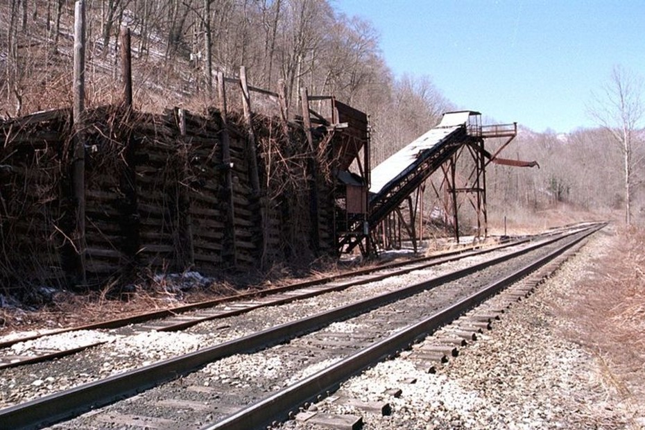
The Southwest loader sat between St Charles and Mayflower but after my era–I’m using it as the prototype for my St Charles loader (Robby Vaughn photo)A view of the St Charles loader mock-up showing the ramp and dump area
Anyway, here are the results, and I’m really liking the scene now. I can’t wait to build the real things! But first the upper deck…
This grainy aerial photo from 1981 (courtesy of the awesome HistoricAerials.com website) clearly shows a single conveyor at the JAD Turner loadout, so I removed “extra” parts from the ’90s loadout to get my design
Here’s the JAD Turner loader near St Charles in the late ’90s with additional chutes added, but I modeled the core dump shed, crusher, and one of the conveyors (Robby Vaughn photo)
Here’s the drawings I did for a JAD Turner loader mock-up using MS PowerPoint along with the supplies needed to build the “paper doll” mock-up
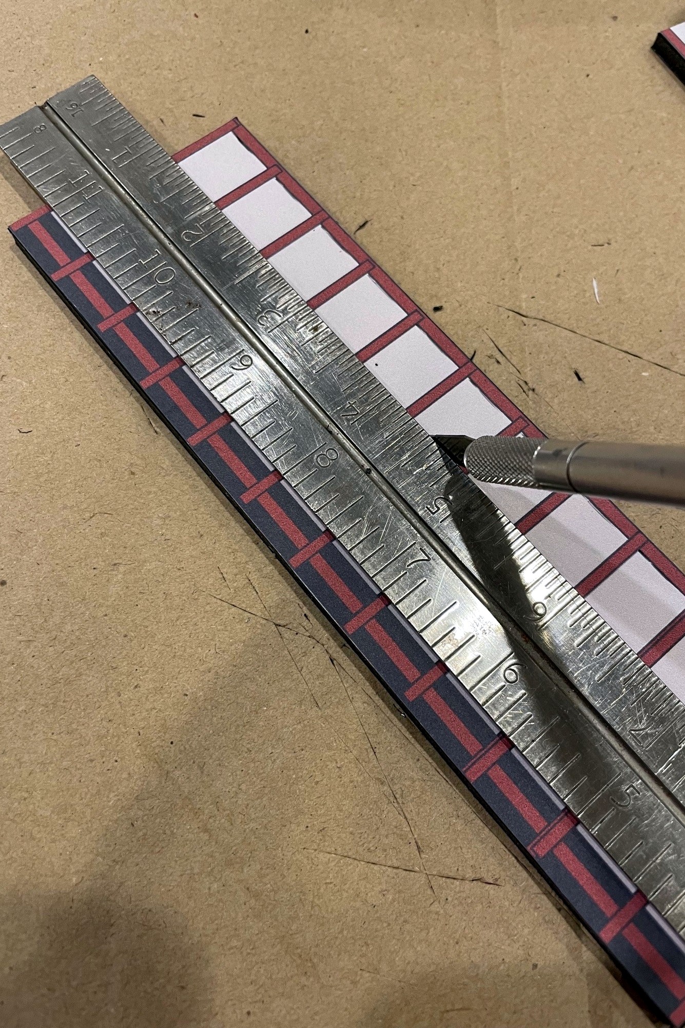
I used a sharp X-Acto blade to cut out the structure details for the conveyors and legs
Once the area has been well scored front and back, it’s pretty easy to just pop it out of the foam core frame
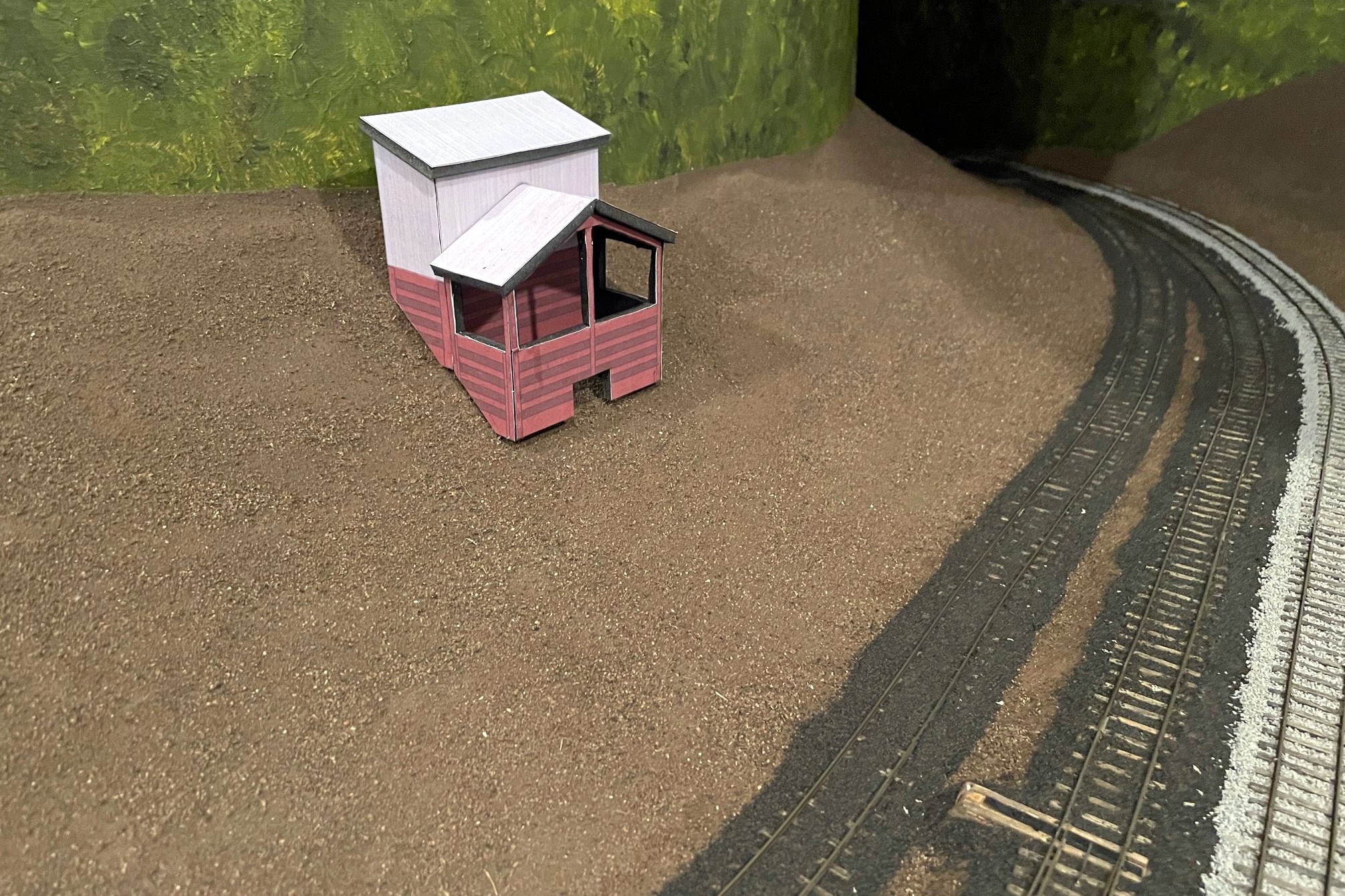
Here’s my dump shed and crusher bin mock-up for JAD Turner. I used an X-Acto to fit it to the hillside
Here’s the finished JAD Turner loader mock-up complete with a little double chute over the rails
This grainy aerial view of the St Charles loader circa 1981 (courtesy of HistoricAerials.com… awesome website) is all I have from which to base my loader model
The Southwest loader sat between St Charles and Mayflower but after my era–I’m using it as the prototype for my St Charles loader (Robby Vaughn photo)
Here’s the finished mock-up for the St Charles loader in place along the wye
Another view of the St Charles loader mock-up showing the ramp and dump area
Here’s the full mocked-up scene with the St Charles Switcher preparing to swap empties for loads at the JAD Turner loader–the St Charles loader can be seen just around the hillside
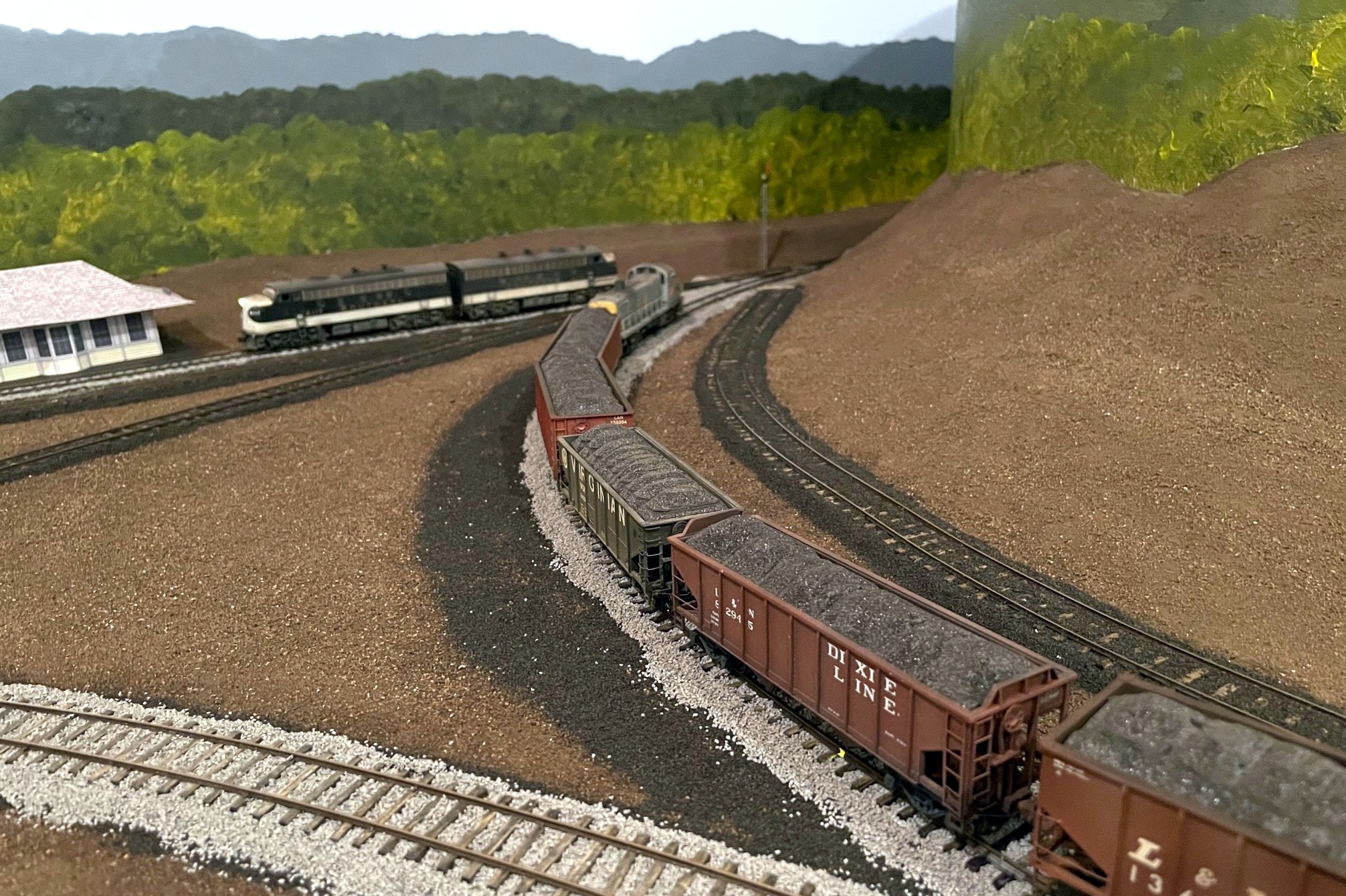
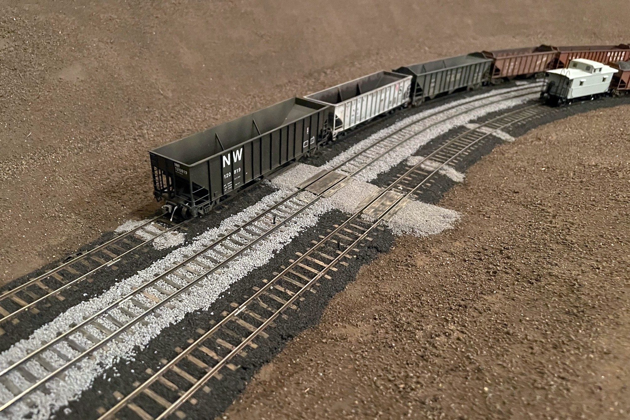
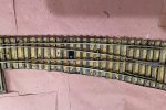
Here’s the St Charles wye with ballast. Note the area of cinders where a track used to be
While I finished the basic scenery forms on the lower deck a few weeks ago, I decided it would be better to ballast the tracks before adding the upper deck benchwork while I still had good access to them. I’m so glad I did because ballasting gives the scenes a much more “finished” look even though there’s still a ton of scenery work to be done. I’ll be honest, I was dreading ballasting the track–I had little experience with ballast, but from that experience I saw it as a frustrating, tedious, and time-consuming job. I have now changed my tune! While it’s still time-consuming, I was able to learn and mature my techniques quickly to avoid the frustration and tedium, so I’ll pass along my method here.
First, I had to determine what kind of ballast I needed. This wasn’t as straightforward as I’d hoped. As best I can tell, most of the tracks in my area were at one time ballasted in cinders harvested from steam locomotives. The steam locos went away in the 1950s, and with them the ability to get cheap and ready cinders for ballast. Photos from the ’80s and ’90s clearly indicate most everything got covered in rock ballast–would the cinders still be around in the 1960s and ’70s? After some digging online, I found that cinders in many places lasted for decades after steam, and in the coal fields, it’s tough to tell cinders from spilled coal anyway, so an added incentive for cinders, at least on sidings and secondary tracks. For the main tracks, photos show the Southern’s ballast in this area was a medium gray. I toyed around with trying to find some actual rock to use as ballast, but in the end I decided on good old Woodland Scenics products made from crushed walnut shells because I can find it readily, it doesn’t cost an arm and leg to ship, and it’s pretty easy to work with. I used fine cinders and medium sized gray ballast in the big shaker containers for this project, and I was able to do the entire lower deck (12′ x 16′) with just under two shakers of each color (4 shakers total).
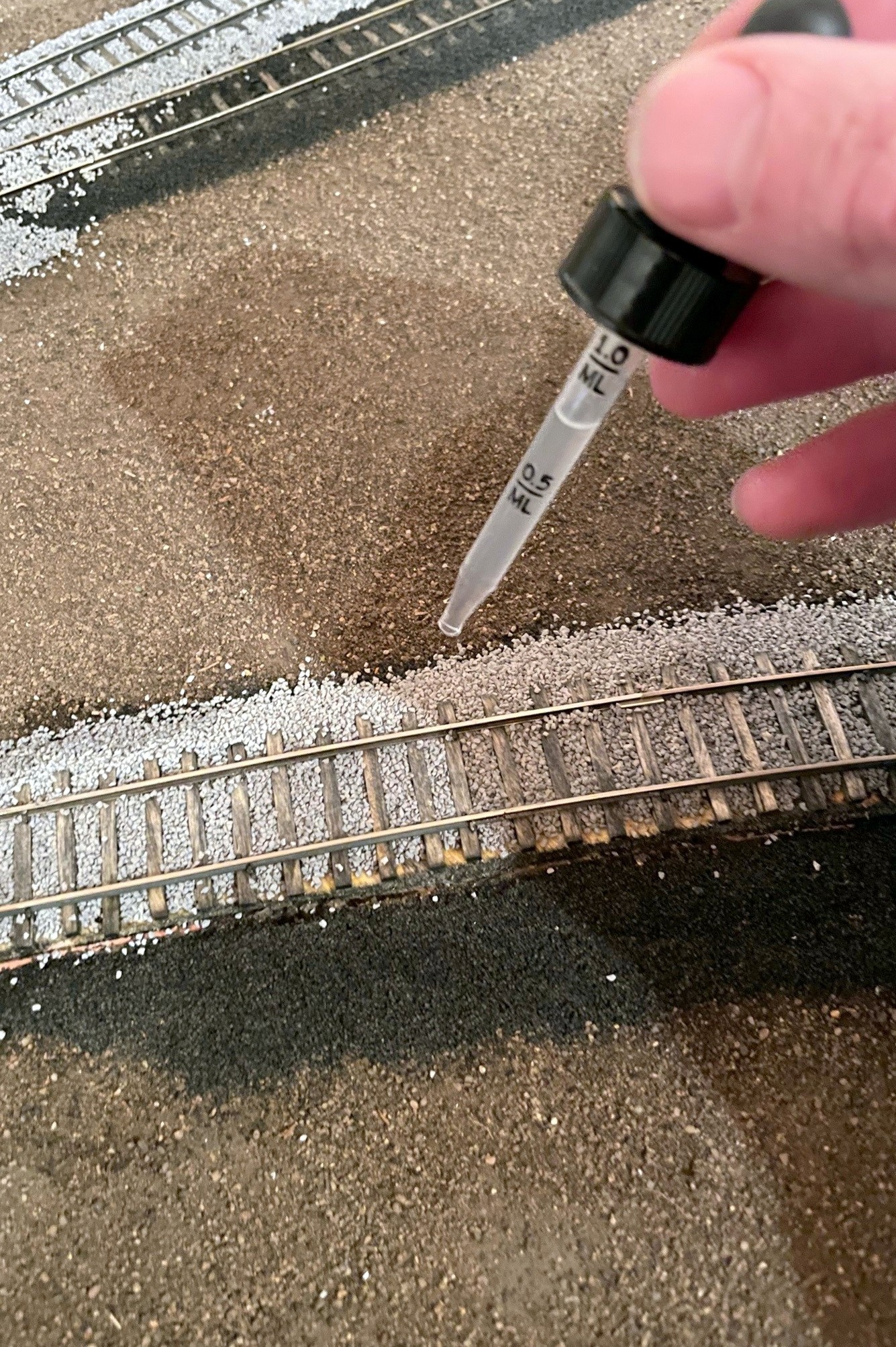
Second, I did a bunch of research on how to apply ballast, and I am so glad I did! In the end, I went mostly with the method Cody Grivno of Model Railroader lays out in the article here. The only other materials I needed were white glue (I bought a gallon), isopropyl alcohol (I used about XX oz), and dish soap. For tools, I used a spoon, a large flat brush, a white glue dispenser (like the ones kids use in school), two small jars with eyedroppers, a work glove, and my fingers. In the glue bottle, I mixed up some “just a bit wet glue” which is about 2 parts white glue, 1 part water, and a drop or two of dish soap–when you squirt it out, it should dissipate from its bead but not run. In one of the jars with an eyedropper, I made a mix of “very wet glue” of about 1 part glue, 6 parts water, and a drop or two of dish soap–it should look about the consistency of milk and absorb into the wet ballast (I’ll explain that in a minute) after a few seconds. You’ll need a LOT of the very wet glue, so you can either make a big batch or mix it on-demand when you run out (what I did… it was a lot of trips). The remaining jar and eyedropper are for the isopropyl alcohol.
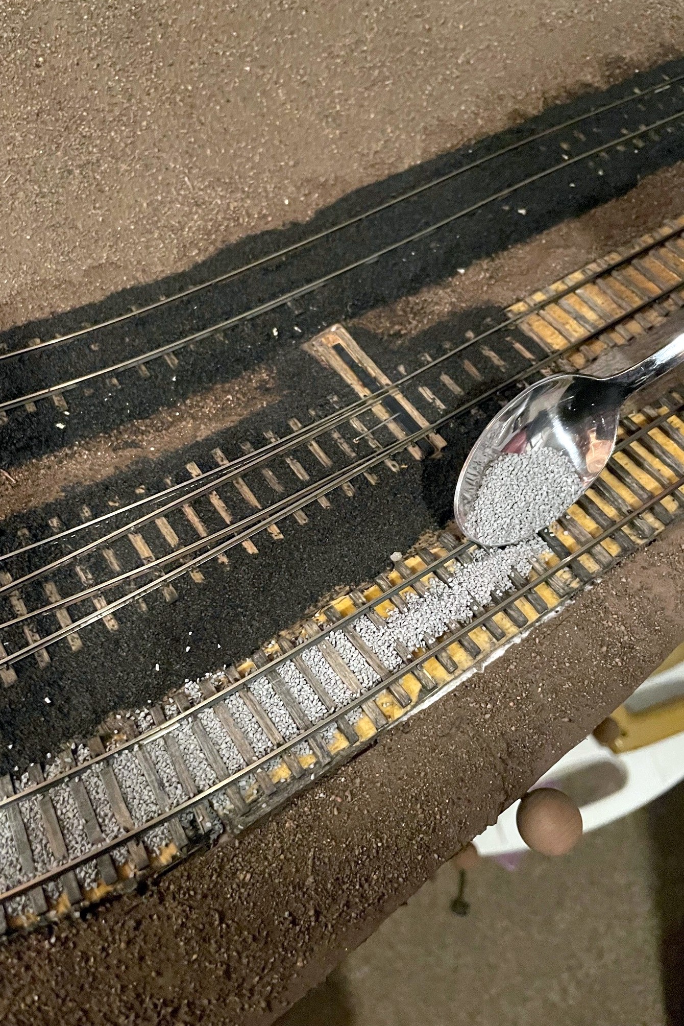
Step 1. Lay down a pile of ballast in the gauge between the railsStep 2. use a finger to spread the ballast between the ties, moving excess to the next section
I worked on the track in about 2 foot sections, usually one track at a time. If you’re doing two ballast colors, determine which ballast should be “lower” and work on that one first–for me, the cinders were replaced by ballast rock, so where they overlap, I did the cinders first. With about half-a-spoonful of ballast, I first apply it to the “gauge” (inside the rails) of the track. It takes a few tries to get a feel for how thick to lay it, but it becomes routine pretty quick. You want just enough that when you spread it the ballast fills the space in between the ties and rails with little on top of the ties and nothing on the rails. I found my finger to be an effective spreading tool, and I just rub it back and forth down the tracks, rubbing any excess ballast to open areas. Cody glues his ballast at this point, but I found it easier to lay the edge ballast first. I applied ballast to the edges by first running a bead of glue from the bottle down the side of the subroadbed and on top of the scenery–this helps the “slope” to hold better. Next I used the spoon to apply ballast inward toward the rail from about the edge of the ties until I couldn’t see the edge of the subroadbed any more. I used my finger again, first to poke the ballast under the rail a bit, then to wipe off the tops of the tie edges, and then to pat down the sloped edges until they looked smooth. I used a brush to clear off any unwanted ballast to outside the range of the glue (I vacuum it up later) and to remove any stubborn ballast from areas my finger couldn’t get to.
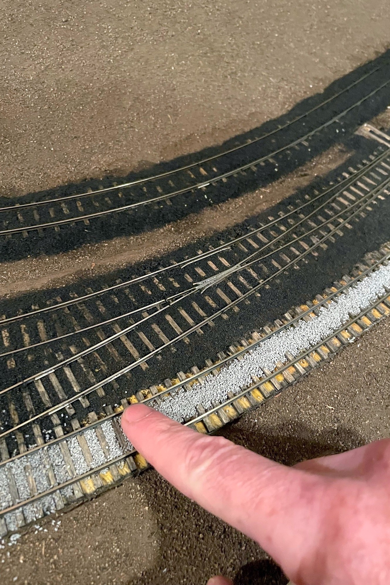
Step 3. Add ballast to the edges of the track, use a finger to work it into the ties, then use a finger to clean it off the ties and shape the slope
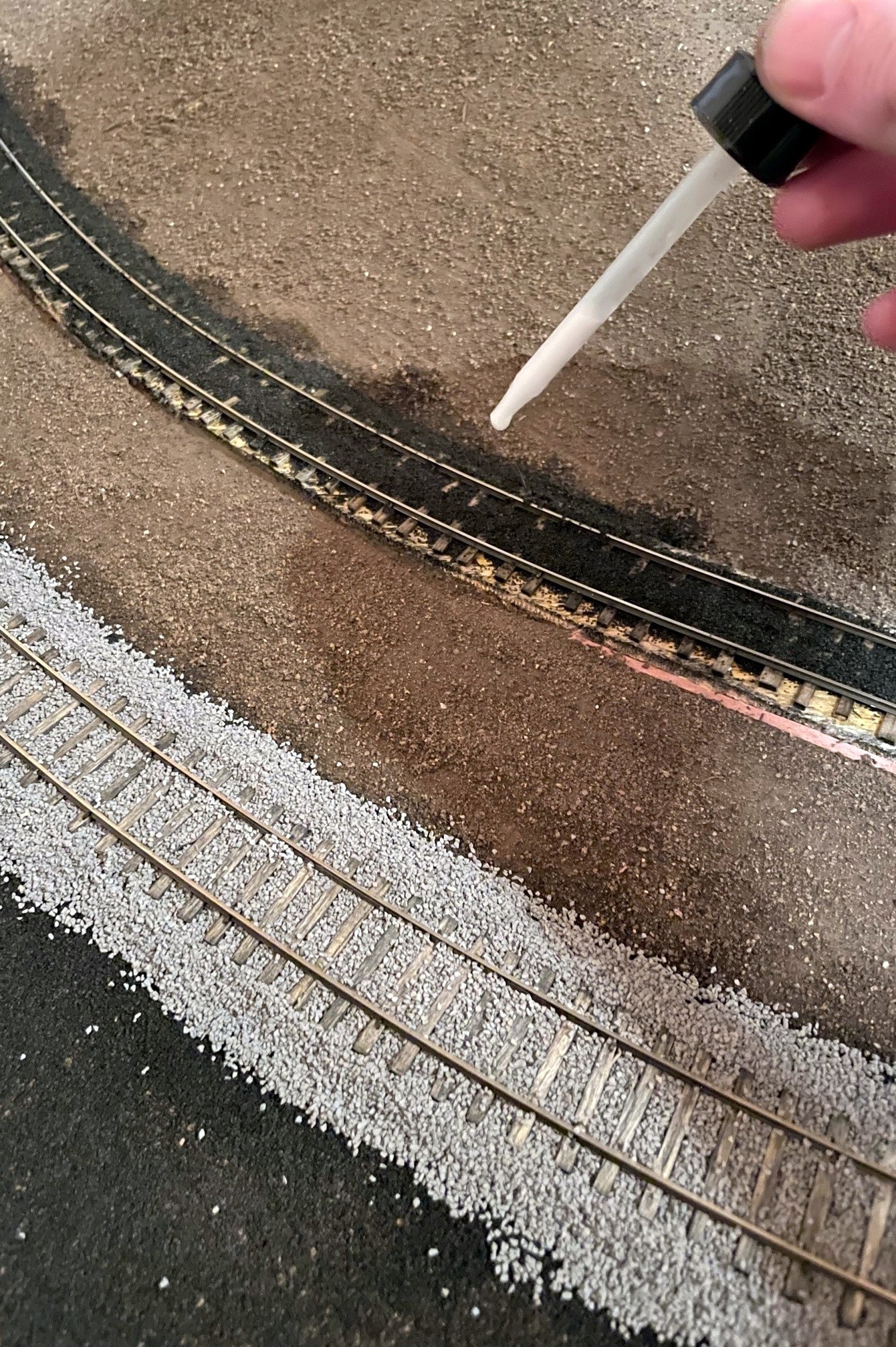
Once I’m happy with the ballast shape, I glue it down. The critical part of this process is to USE THE ALCOHOL AS A WETTING AGENT FIRST! If you just add the glue, the ballast will float (and float away) which makes a frustrating mess. You can avoid this by first saturating the ballast with an eyedropper of isopropyl alcohol–just drop until everything looks wet. I follow the alcohol wetting with the very wet glue, making sure I apply drops to every section of ballast until things were saturated and it took a couple seconds for the glue to soak in. If you drop a big glob of white glue that somehow didn’t get diluted, no worries–just dilute it with some alcohol, and it will likely settle in just fine. I wet and glued each section by starting with the gauge between the rails, then moving to the edges. I found for the edges it’s better to start the alcohol low and work up to keep things in place, and its better to start the glue high and let it work down.
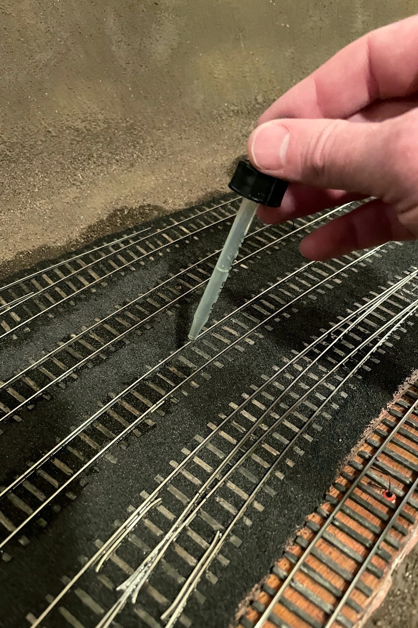
Step 4. Using a dropper, soak the ballast with isopropyl alcoholStep 5. Saturate the wet areas with wet glue
Turnouts require a bit more care, and I probably didn’t take all the care I should have… it worked out ok, but I spent a couple hours massaging my turnouts to get them working smoothly again. I spread the ballast a little less thickly between the ties to make sure the points wouldn’t catch, and I took care to avoid putting ballast in the area of the throw. No matter how careful I was, there was always some piece determined to get stuck in the throw, so I used the brush (and the occasional X-Acto blade) to fish out any offenders. I used the very wet glue sparingly in these areas, but there was still some glue that stuck to the top of the ties causing the points to stick a bit. I believe Cody’s method is to drop the glue in first, then add the ballast under the points, and I think I’ll try this next time.
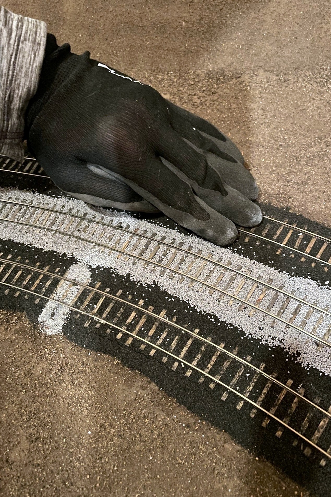
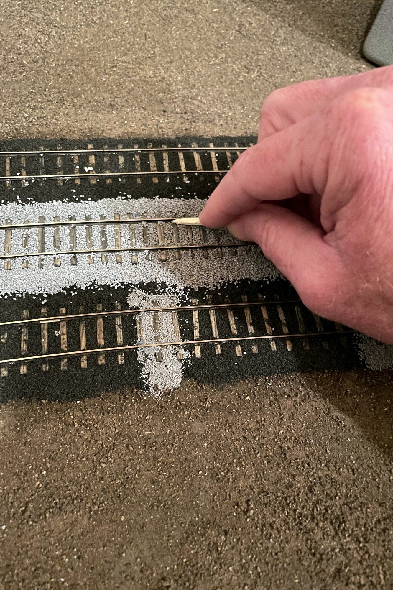
Step 6. Clean off any excess ballast–I use a work glove for thisStep 7. Clean any remaining ballast from the web of the rail–I use a combination of a matchstick and fingernails
After letting the glue dry overnight, I clean up any excess ballast. First, I use a work glove and rub it over the top of the ties and edges to knock off any obtrusive pieces. Next, I clean out the area in the web (sides) of the rail using a matchstick rubbed back-and-forth followed by a fingernail. I used a flathead screwdriver to clean out flangeways if necessary. I cleaned up any excess with a vacuum. You’ll inevitably find spots you missed with the glue, but it’s easy to just add more ballast, drop some alcohol, then drop some glue to repair.
Ballast is scenery, so I also wanted it to tell a story. Because track repairs would have been made with gravel instead of cinders in my era, I picked a few spots along the cinder-ballasted yard tracks to fill with gravel (in this case, Woodland Scenics fine gray ballast) to simulate a replaced tie. I like the look! I also picked a few spots in prominent areas to lay some cinders on the scenery to go underneath the ballast rocks to show that some tracks were once cinders but had now been ballasted with rock. I also laid a thin layer of cinders in areas where I know tracks used to be, even though I don’t model them in my era. Finally, I added extra cinders to areas under tipple chutes and where locomotives sit to represent spilled coal and grime. I’m pretty happy with how these “extras” turned out, but they won’t fully tell the story until more scenery is complete.
The St Charles yard where the main is clearly visible. The gray areas on top of cinders represent tie repairs after the age of cinders
Ok, the ballasting was the last step before adding the upper deck, but you’ve heard that before… We shall see.
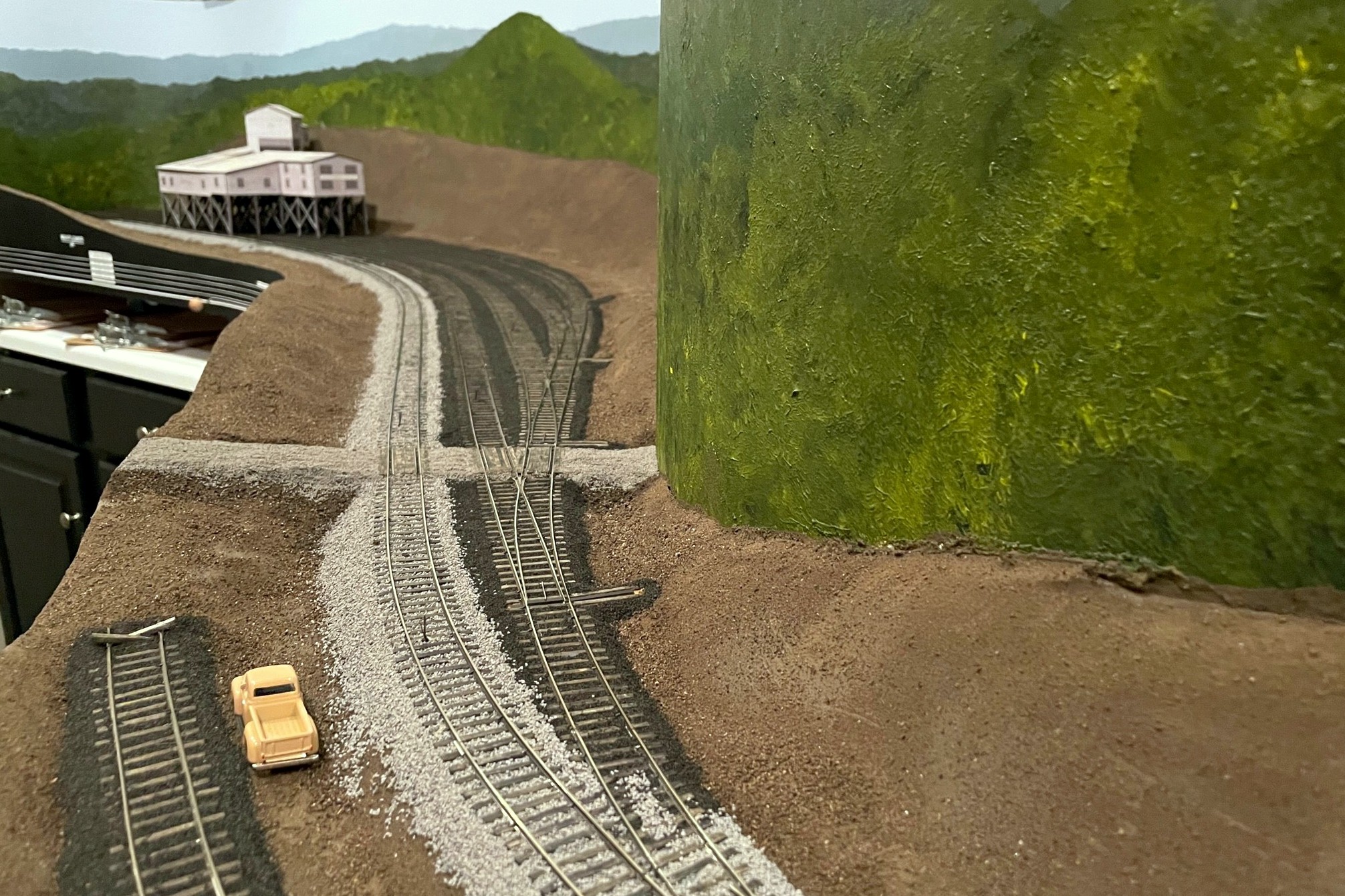
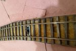
Here’s the finished ballast at the Mayflower tipple–the road is made from fine ballast as well
Step 1. Lay down a pile of ballast in the gauge between the rails
Step 2. use a finger to spread the ballast between the ties, moving excess to the next section
Step 3. Add ballast to the edges of the track, use a finger to work it into the ties, then use a finger to clean it off the ties and shape the slope
Step 4. Using a dropper, soak the ballast with isopropyl alcohol
Step 5. Saturate the wet areas with wet glue
Step 6. Clean off any excess ballast–I use a work glove for this
Step 7. Clean any remaining ballast from the web of the rail–I use a combination of a matchstick and fingernails
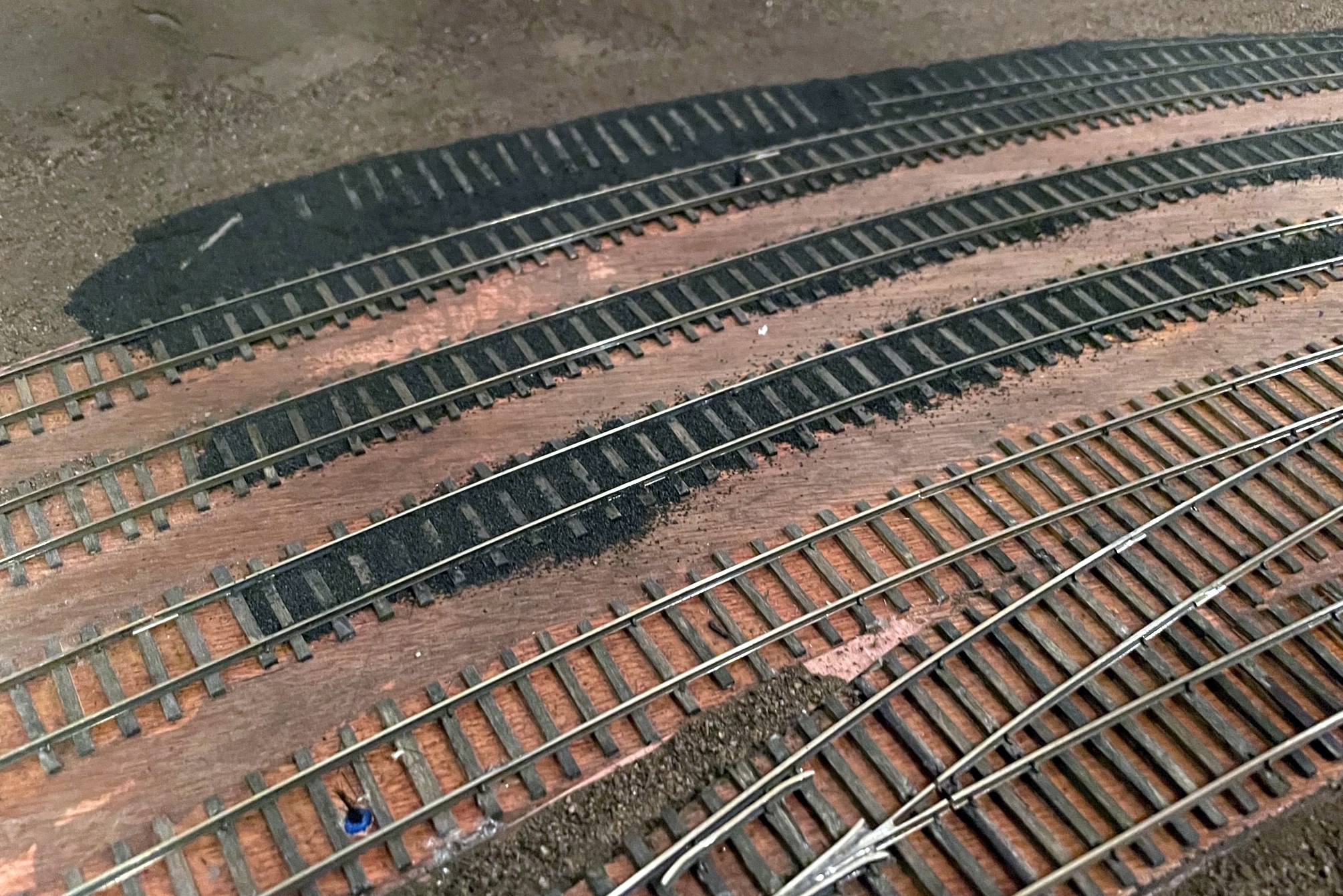
For yards, I did multiple tracks at a time, starting with the gauge, then filling in the areas between tracks
Even when working on multiple tracks at a time, I still wet and glued the gauge portion of all the tracks first
Here’s the finished ballast at the Mayflower tipple–the road is made from fine ballast as well
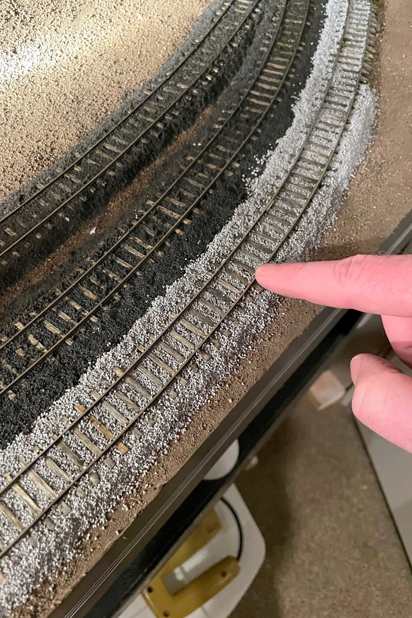
Transitioning from rock to cinders is done abruptly, but I sprinkle rocks to make a better transition
The St Charles yard where the main is clearly visible. The gray areas on top of cinders represent tie repairs after the age of cinders
Here’s the St Charles wye with ballast. Note the area of cinders where a track used to be
I piled more cinders on top of the rails where the engines sit to simulate grime build up
Handbrakes in action holding empties securely above the Mayflower tipple
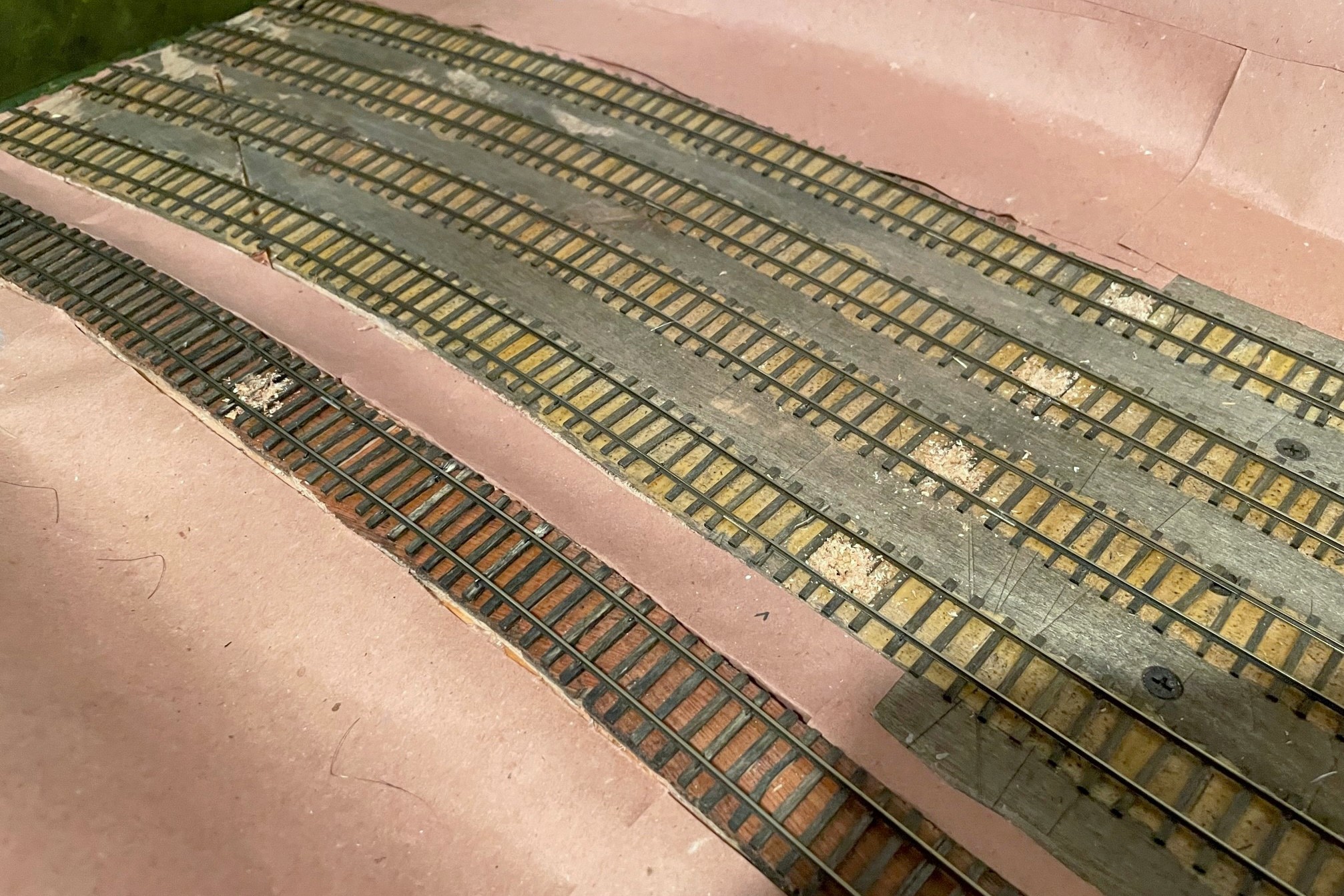
The ability to set handbrakes to keep cuts of cars in place on a grade is a crucial part of railroading, and a model railroad is no different, especially one set in the Appalachians. I’ve covered my technique for building manually deployable handbrakes via a retractable wire between the rails (article here), but the controllable brakes are complicated to make and install, so I reserve them for areas where I’ll be holding long cuts of cars on a steep grade or for where I need to hold a car for a while and then let it loose for some “gravity assisted switching.” But there are several dozen spots on the layout where I’ll need to spot small cuts of cars on slight grades, so for these areas, I wanted something simpler. I also like free-rolling cars, so tricks like putting a tiny spring on the end of one of the axles was also off the table–it needed to be something in the track. Enter the cheap plastic paintbrush! Each paintbrush handbrake costs just cents to make, and I can easily make and install a dozen in under an hour.
I picked up a box of 100 inexpensive plastic paintbrushes a couple years ago when the local Christian bookstore was having a big sale. I didn’t know how I would use them, so I put them away for a rainy day. That day came when I was playing around with different ideas for holding cars in place. It needed to be something I could roll cars and locomotives across easily without derailing or causing too much friction that would also be sturdy enough to hold a car when spotted over the brake. I first tried two methods that I’ve seen work for others. The first is a little dot of CA on top of the rail, but many of my spotting points were just too steep for this. Next I tried little lengths of fishing line mounted between the rails–these are good because they’re tough to see and work pretty well, but they make a noticeable “plink” every time they clear an axle or a hopper bay… in sections of the yard where I had several in a row, it sounded like a tiny music box playing a discordant tune!
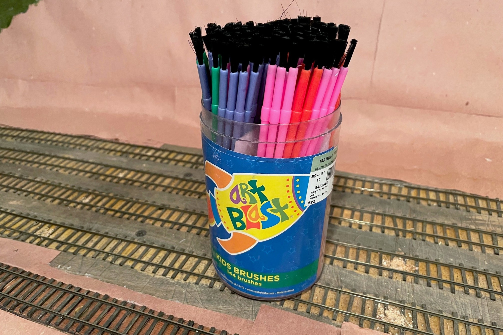
The starting point for handbrakes are inexpensive plastic paintbrushes from an art or hobby store
Then I remembered the brushes. The plastic bristles are pliable enough to give when trains are moved across them but stiff enough to hold a car when no other force is exerted. They could also be trimmed both in height and in density using a pair of scissors. They are certainly more noticeable than the fishing line or CA dots, but my hope is they’ll blend right into dirty coal-covered tracks, and those that don’t blend in can be painted to look like weeds. Even with nothing to disguise them, I find they don’t draw the eye much anyway.
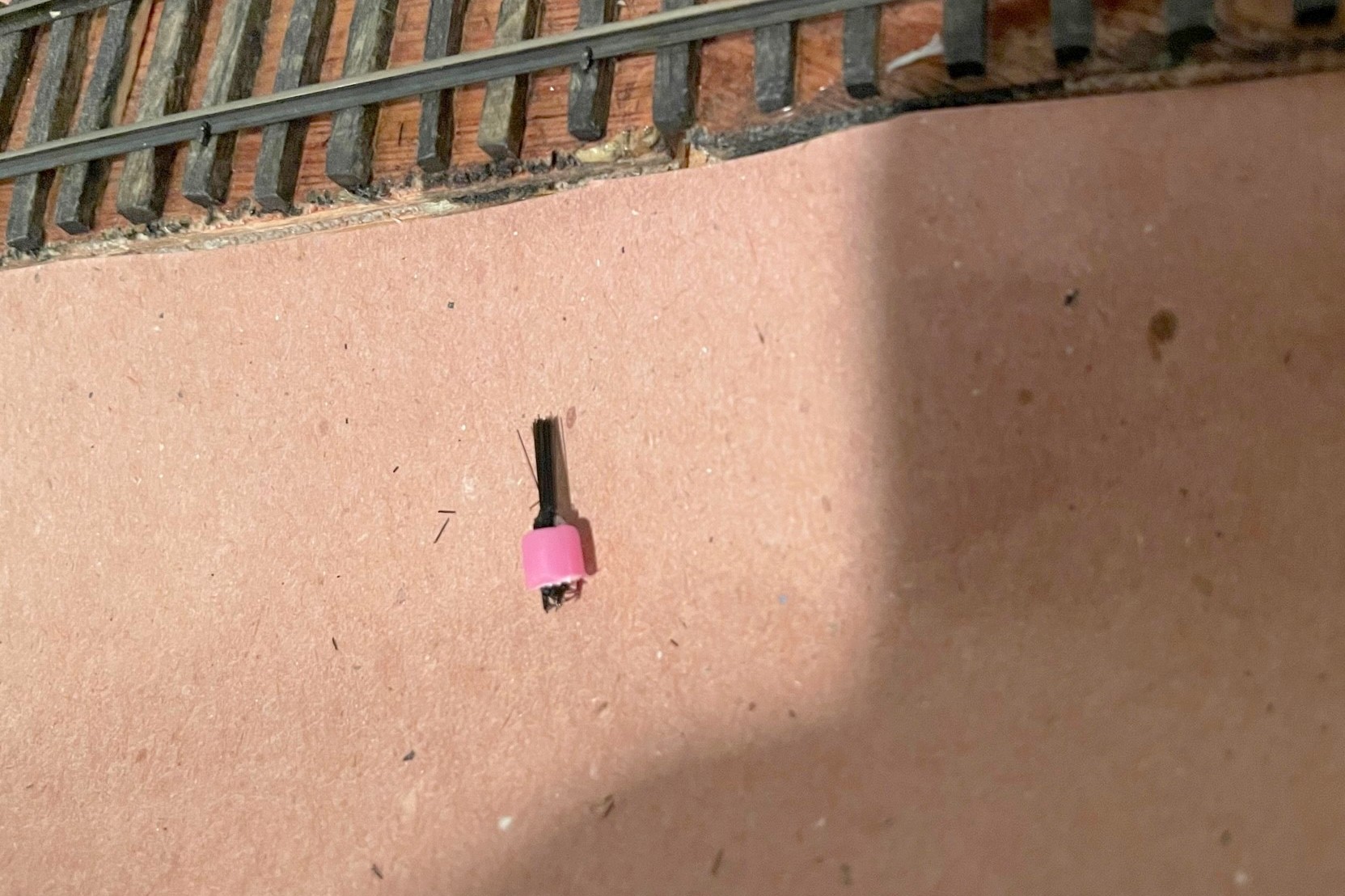
Step 1 is to locate where you need the brakes and drill a hole–the hole is offset to avoid wear-and-tear on air hoses
The first step is to locate where you want to install the “brake.” Figure out where you want the car or cut of cars to sit, then mark the spot where the most downgrade axle will sit–this is where you want the brake. In some cases, like the end of a track, you can mark the spot of the downgrade axle of the upper truck–I use this at the end of stub tracks where I need all the room I can get. For tipple tracks, I find it useful to have up to four handbrakes per track. One at the uphill end of the empty track to hold a full cut of empties, one just above the tipple to hold a shorter string of empties, one just below the tipple to hold a shorter string of loads, and one just before the fouling point of the downhill switch to hold a longer string of loads (or any “gotaways”).
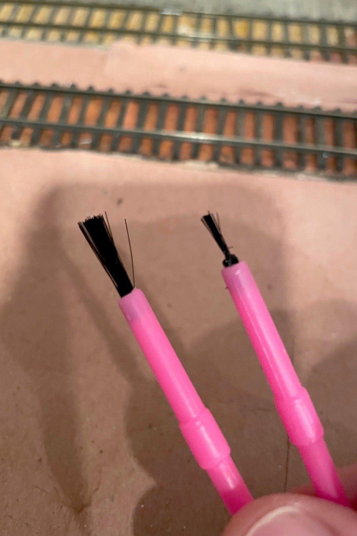
Starting and ending points with the brushes, just a little off the top and thinned down with scissorsThe finished “brake” ready to install between the rails
The second step is to drill a hole between the ties for each hand brake location. I found a 5/32″ bit drilled about 1/4″ deep worked for my paintbrushes, and I offset my holes closer to one rail to avoid constantly hitting delicate air hoses on cars. To prep the paintbrush, I first cut off about 3/16″ of the bristles with scissors–the idea is to have them tall enough to catch axles but not the sills of the cars or cut levers. Then I thin out the bristles by repeatedly cutting into the brush with just the tip of the scissors while rotating the brush around. How much you thin it out depends on the grade and how many cars you want to hold, but for my light grades, I trim down to about the last 20 or so bristles. It’s easy enough to thin them a bit more once they’re installed, and if you get it too thin, it’s easy to just make another. Then I use scissors and cut off the brush end of the paintbrush leaving about 3/16″ of the plastic handle to keep the bristles secure. Installing them is usually a press fit, but if they’re loose, a little carpenter’s glue will help hold them in place. I press them down until the handle is below the ties where its bright color will be covered up by ballast.
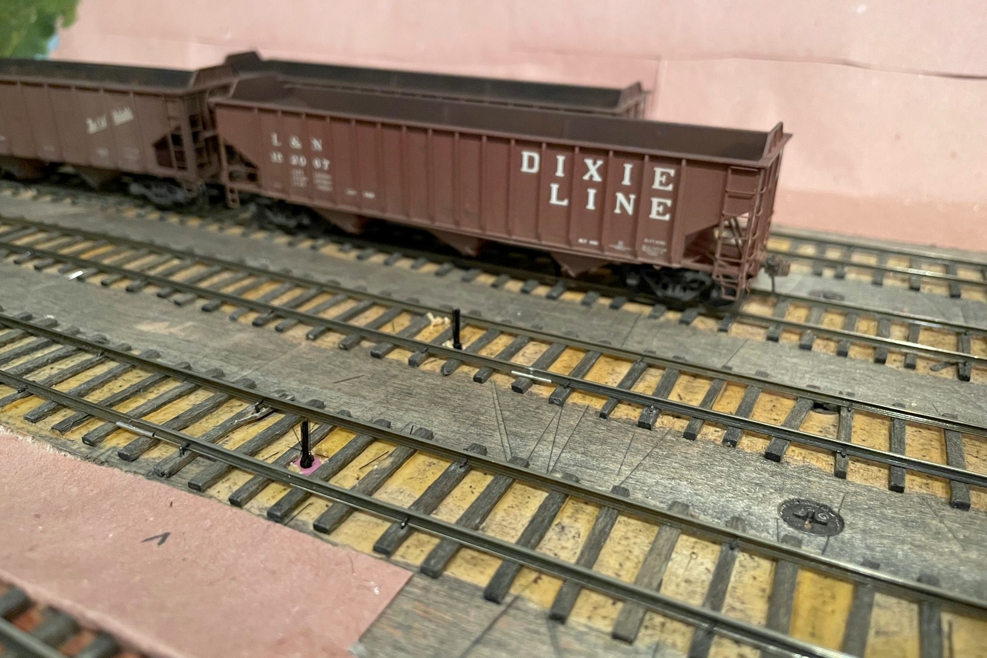
Paint brush handbrakes installed between the rails
The final step is to test the brake by running strings of cars across them to make sure they don’t derail and don’t cause any noticeable jerking movements in the cars (if you look closely, you’ll see some movement, you just want to avoid it being distracting). When you let go, the cars should roll and then come to a gentle stop once they hit the brake. Also test a locomotive across each brake to make sure it doesn’t interfere with the trucks (this is the most stressing pressure on the brake). On steeper grades, you may find having a few brakes in series is needed to stop a string of rolling cars, or you may have to spot the cars exactly on the brake to prevent them from rolling in the first place. It’s easy enough to add and remove these brakes while you’re trying to figure things out. In the end, I’ve found this is a great way to hold cars in place without the worry of damaging cars or scenery, and it’s tough to beat the price and ease of installation!
Finished “handbrakes” to hold the loaded cars in front of the Mayflower tipple mock-up
The starting point for handbrakes are inexpensive plastic paintbrushes from an art or hobby store
Step 1 is to locate where you need the brakes and drill a hole–the hole is offset to avoid wear-and-tear on air hoses
Starting and ending points with the brushes, just a little off the top and thinned down with scissors
The finished “brake” ready to install between the rails
Paint brush handbrakes installed between the rails
Finished “handbrakes” to hold the loaded cars in front of the Mayflower tipple mock-up
Handbrakes in action holding empties securely above the Mayflower tipple
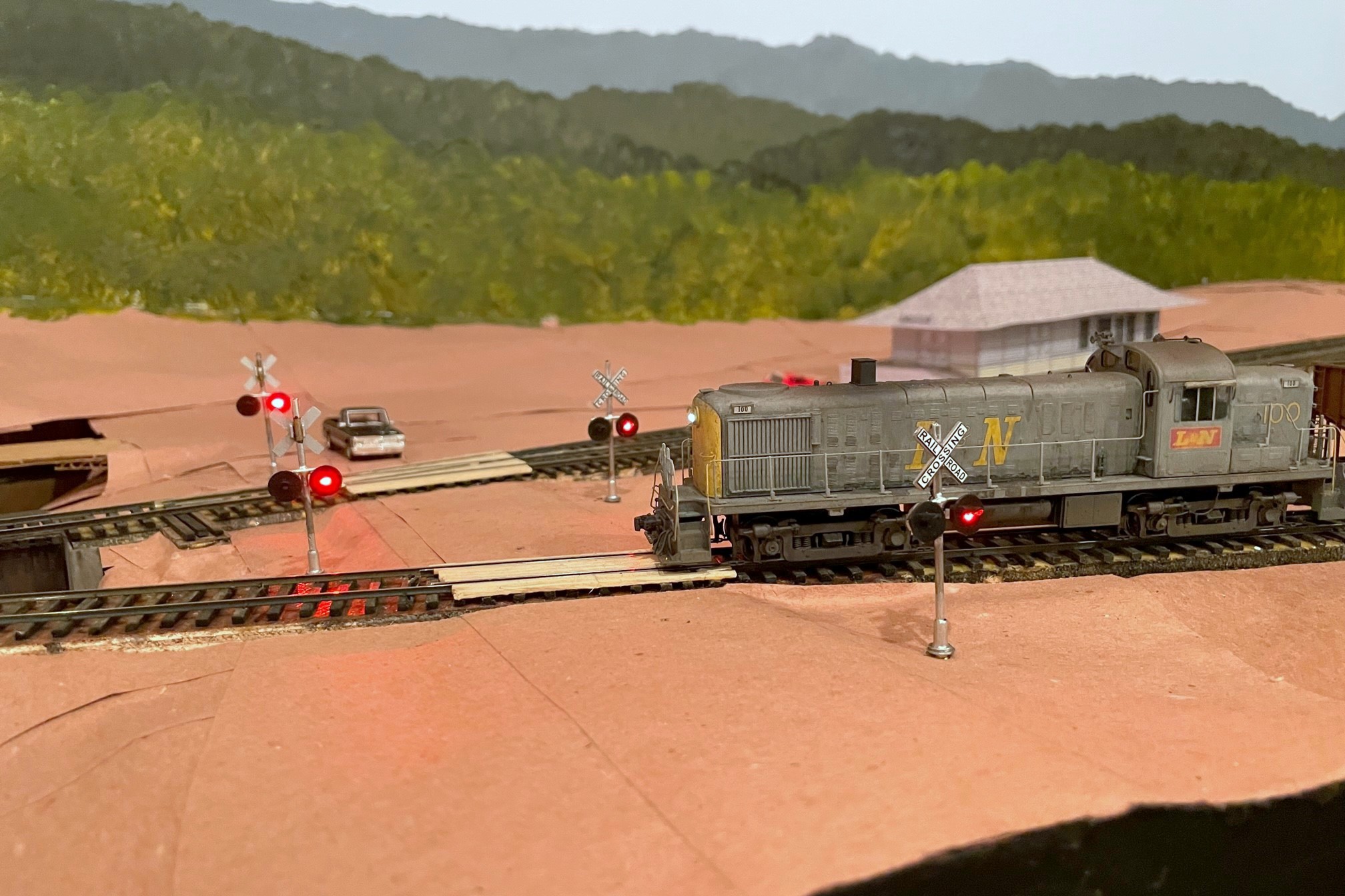
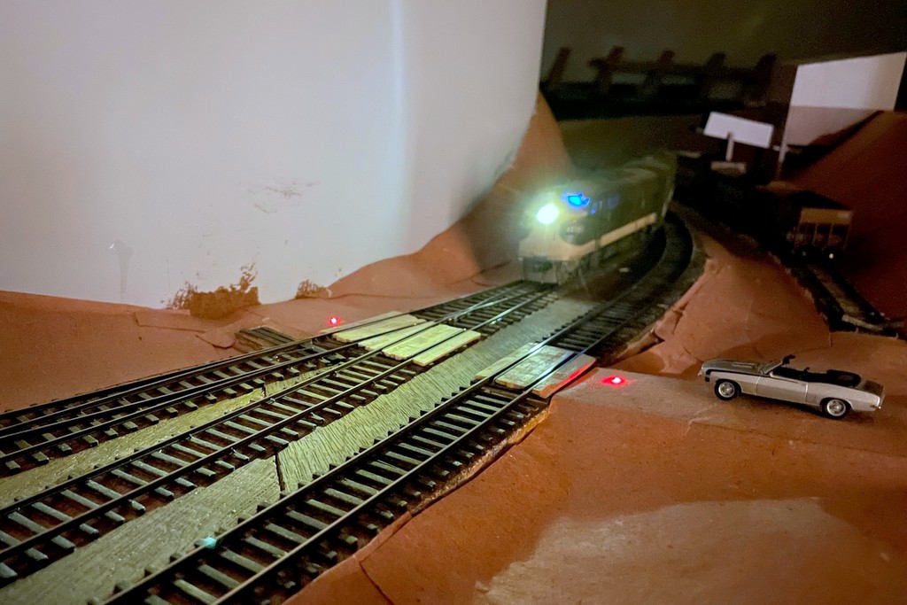
The CV Local led by L&N RS3 100 crosses Bonny Blue Road with its newly installed crossing flashers
Many of the grade crossings on the St Charles Branch didn’t have flashing signals and were protected by flagmen or fusees (see how I simulate fusees here), but a few of the more prominent crossings were protected by automatic flashing signals and bells. One of those crossings is Bonny Blue Road which crossed two legs of the wye in St Charles. I was looking for a way to make these signals work automatically with nothing required of the crews (beyond sounding the horn for the crossing) and no hardware needed on any rolling stock. I quickly settled on using IR sensors mounted near the tracks to trigger the circuits required for the crossing. While many of the major manufacturers of railroad electronics offer circuits for flashers and for triggering based on sensors, there seemed to be a lack of good, simple options for the sensors. So I did what many of us do when we’re looking for something–I turned to eBay.
I found a lot of products for flashing crossing signals, but one it particular caught my eye. A company called “WeHonest” was offering what looked to be decent looking LED signals that came with a flashing circuit for a very reasonable price. Being a little suspect of a foreign company calling itself “WeHonest,” I needed four signals, so I ordered a couple sets and hoped for the best. I ordered the signals with two heads instead of four (front and back) because my signals would only been seen from one direction, and the ones with four heads looked too thick front-to-back (I plan to add dummy heads on the back later). When they arrived a couple weeks later, I was impressed with the quality for the price. The lettering is easily readable, the construction is mostly metal, and the size and shape are good for HO scale. I had to clean up some areas of the metal crossbucks, and some of the silver paint flaked off, but these were easy fixes. I initially hooked up the flashing circuit to a pushbutton on the fascia, and the flashing circuit worked flawlessly and controlled all four signals in a synchronized manner.
The signal piece was solved, so now I needed a way to automatically control them. My confidence in “WeHonest” was bolstered, so I explored their options. They offer a “model train detector automatic signal controller crossing system trigger etc” (also called a “master board”) which shows a diagram of how it can be configured to trigger a grade crossing flashing circuit using simple, single-unit IR sensors that don’t require a broken path. I also needed a circuit that could support four sensors due to the tracks that would trigger this grade crossing, and while the board only supports two sensors, their diagrams show that you can connect more sensors via separately available splitter cables. They also offer a sound effect circuit with multiple grade crossing signal bells (and a rooster). I ordered a master board, sound effect board, two splitters, and some additional IR sensors.
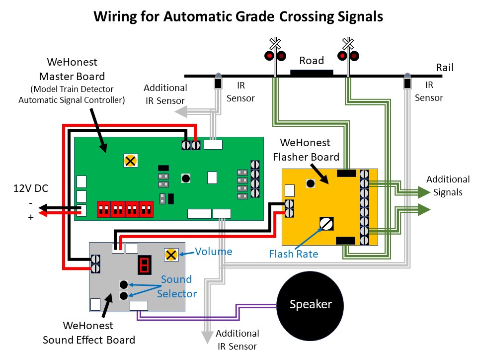
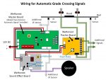
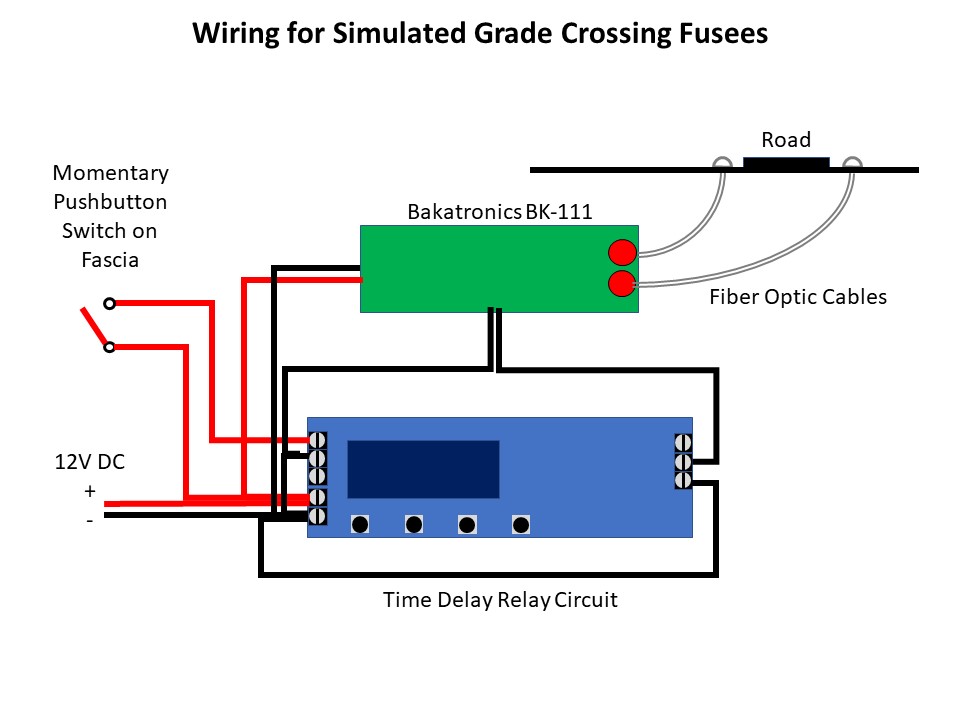
Wiring diagram showing the connections needed between the three circuit boards, signals, and sensors
The documentation you see on eBay is all you get, so it took some studying and tinkering to set things up, but it wasn’t difficult. The basic idea is the master board is connected to 12V DC and the IR sensors. The sound effect board and flasher circuit are daisy chained off the 12V DC “output” side of the master board which is only live when the IR sensors are triggered. The only surprise on wiring was there are no normal contact screws for the 12V DC input, only a plug for an adapter and a specific connector type (both of which are sold separately). I found a plug off an old RC helicopter I disassembled years ago that did the trick. I mounted all three circuits and the speaker on a piece of masonite to keep the wiring tight and organized. Rather than use the supplied speaker, I attached a pair of baffled cube speakers I had pulled out of a locomotive when I replaced it with a Scale Sound System speaker.
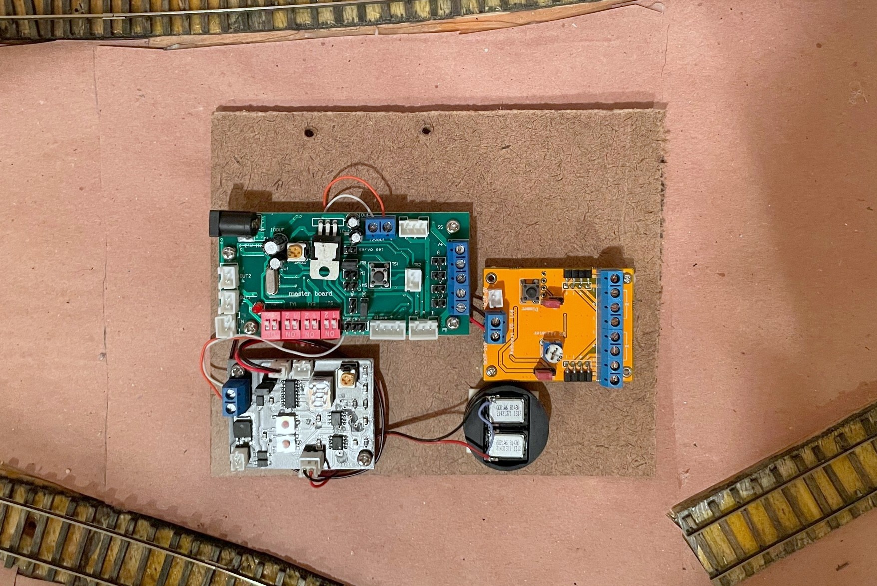
I mounted all three circuits and the speaker on a single piece of masonite to declutter and protect the wires
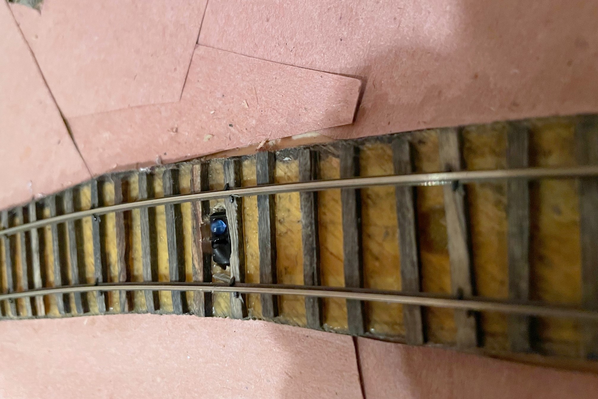
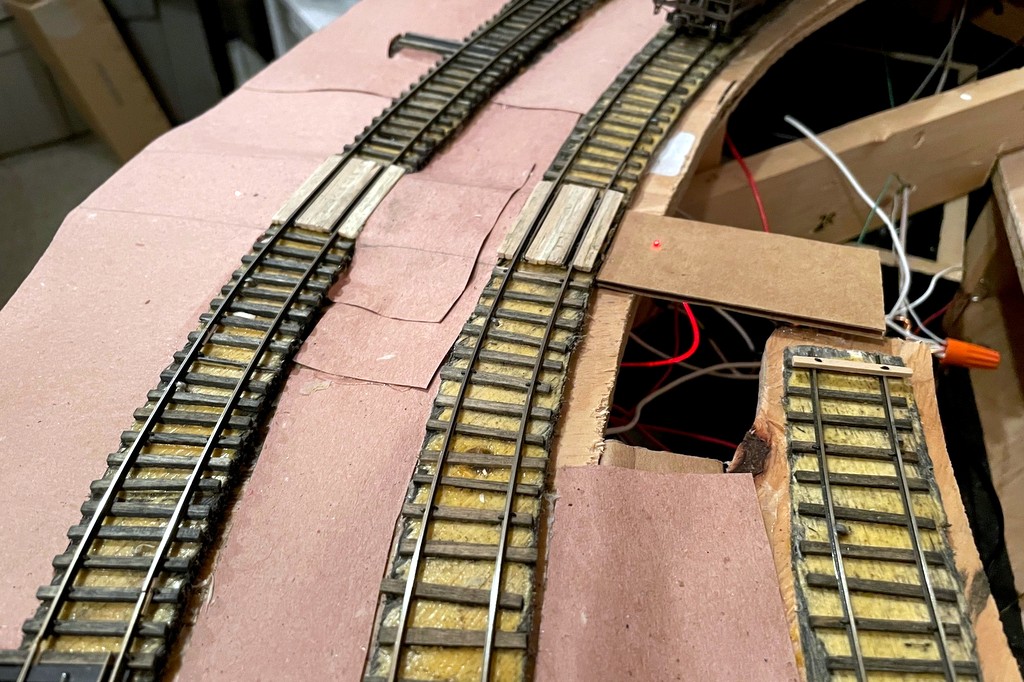
I installed the IR sensors between the rails and ties as the company indicates in the pictures. When anything passes over it within a couple inches, the IR sensor is triggered. There is no documentation on how the sensor works, but it has two elements, a blue dome and a black dome. I can only speculate that it transmits IR from one dome and receives reflected IR in the other dome. When I hooked everything up, it worked great… with two IR sensors plugged into the two separate sensor inputs on the master board. When I tried to use all four IR sensors, it would trigger the circuit no matter what I did even if nothing was present. I noticed some sensors were more sensitive than others, so I experimented with different placements and combos and even the positioning of the elements within the sensor. Unfortunately, I destroyed one of my sensors in the process, but thankfully they’re inexpensive, and I found the WeHonest customer service to be very responsive and helpful!
Here’s an IR sensor with a portion of the black dome covered in electrical tape to decrease its sensitivity
When my replacement sensors arrived, they did the exact same thing as before. Two sensors worked fine, four sensors triggered the circuit even with nothing present. I really liked the overall operation of these circuits, so I kept experimenting to see what might work. I speculated that the circuit detects based on a threshold of received IR energy–with one sensor, the ambient IR was low enough to stay below the threshold, but with two sensors, the ambient IR increased above the threshold to make it appear a train was present. I found that if I covered a portion of the black domed element on some of the IR sensors, it would keep the circuit from triggering but would still trigger if a train passed. After playing around, I found covering about 60% of the black element of all IR sensors with a small piece of electrical tape made everything work as intended.
Now that I’ve worked out the kinks, I’m very happy with the crossing! I’m able to control the sensor sensitivity via the electrical tape, I can control the flash rate of the LEDs via a dial on the flasher circuit, I can select the bell sound from one of several good options on the sound effect circuit, and all of this works automatically with no actions needed from the crew. I have two more flashing grade crossings to go on the upper level, and I’m satisfied enough that I’ve already ordered the parts to replicate this installation on those crossings.
Wiring diagram showing the connections needed between the three circuit boards, signals, and sensors
I mounted all three circuits and the speaker on a single piece of masonite to declutter and protect the wires
I mounted one IR sensor between routes on a turnout because either route requires the crossing signals to activate
Here’s an IR sensor with a portion of the black dome covered in electrical tape to decrease its sensitivity
The circuits installed under the layout
The CV Local led by L&N RS3 100 crosses Bonny Blue Road with its newly installed crossing flashers
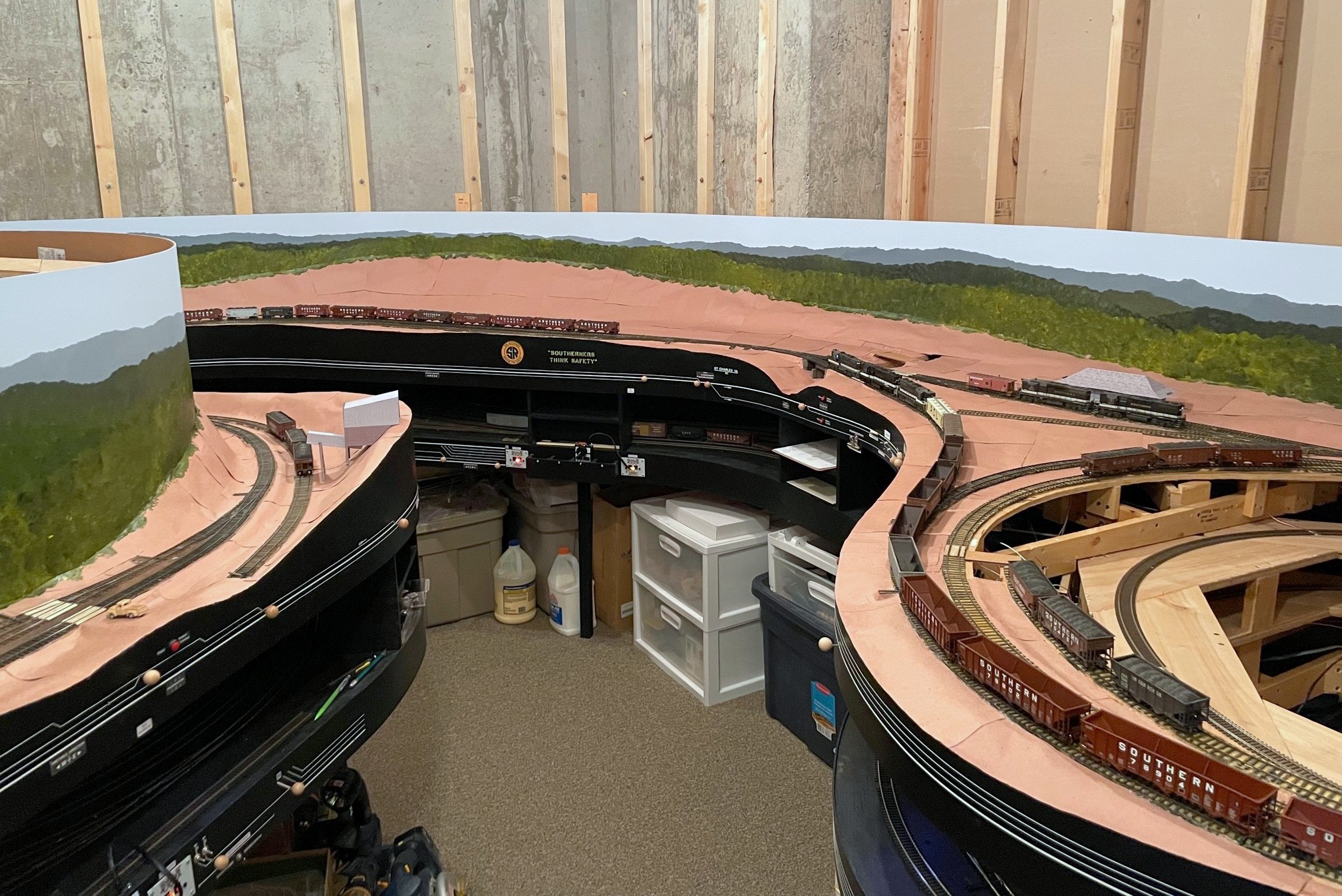
Here’s a look at last Saturday’s progress including finishing most of the lower level scenery base and painting the rest of the backdrop
I had a happy aligning of the stars on Saturday where my wife was gone for the day, I didn’t have any big “chores” to do, and I had just learned how to paint backdrops! All that combined into a day spent furiously trying to finish up the lower-level scenery forms so I could paint the rest of the lower-level backdrop. It was a good day, and I’m pretty happy with the results. I learned that the painting is my favorite part, roughing in the scenery with cardboard strips is my second favorite, and papering over the cardboard with section after section of red rosin paper is a distant third. Round 2 of backdrop painting went a little smoother than round 1 as I think I had a better grasp of the techniques, and the paint brushes seemed to work better on their second use. I liked the results of round 2 so much I went back and redid some sections of round 1.
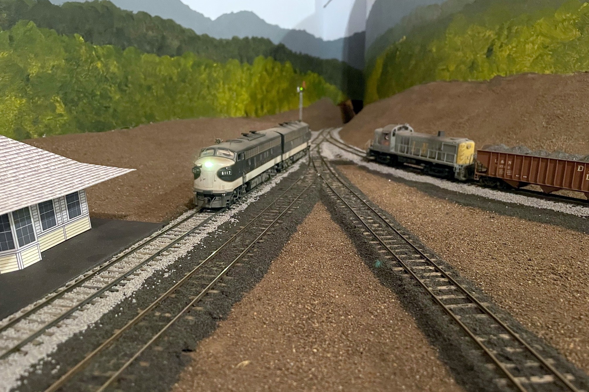
The St Charles Local traverses the wye with the newly painted backdrop. It will soon descend through the backdrop in the corner, a hole much tougher to spot now
The scenery covers over the hidden track along the back wall that joins St Charles and the Mayflower section, so I decided to do a test run… I can now verify that I can indeed – by twisting at odd angles, reaching into small gaps, and fishing it out the last couple feet with a long string of hoppers – free a stuck train from the most remote part of my hidden track! Lesson learned–when you use hot glue for scenery, it tends to leave a lot of strings hanging down, and go figure, locomotives don’t pick up electricity so well when their wheels are covered in bits of glue string! A little wheel cleaning and some extra sweeps of the hand through the area (again at odd angles via small gaps), and trains now traverse this area nicely.
Where the two lower-level scenes transition–the backdrop on the right is lower than the left, hence less blue sky
I’ve only got one section left that still needs a backdrop and scenery forms, over the helix from staging. Painting the backdrop in the corner was the big barrier to adding this, so that will likely be the next step, and the LAST step before building upper-level benchwork… it’s getting pretty real.
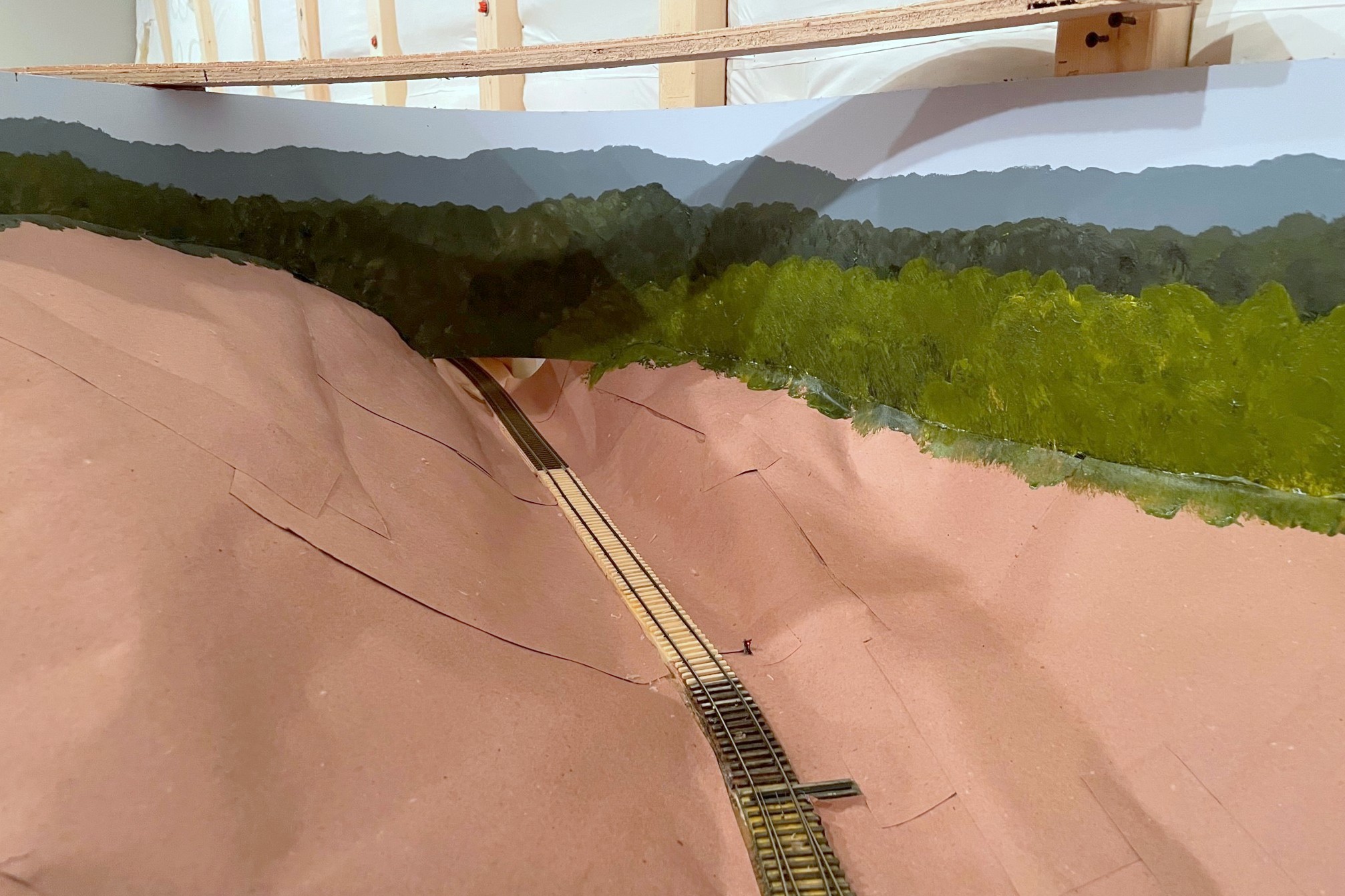
Here’s where trains will leave the lower level and enter the helix to the upper level–I think the backdrop painting along with a few trees will hide the transition well
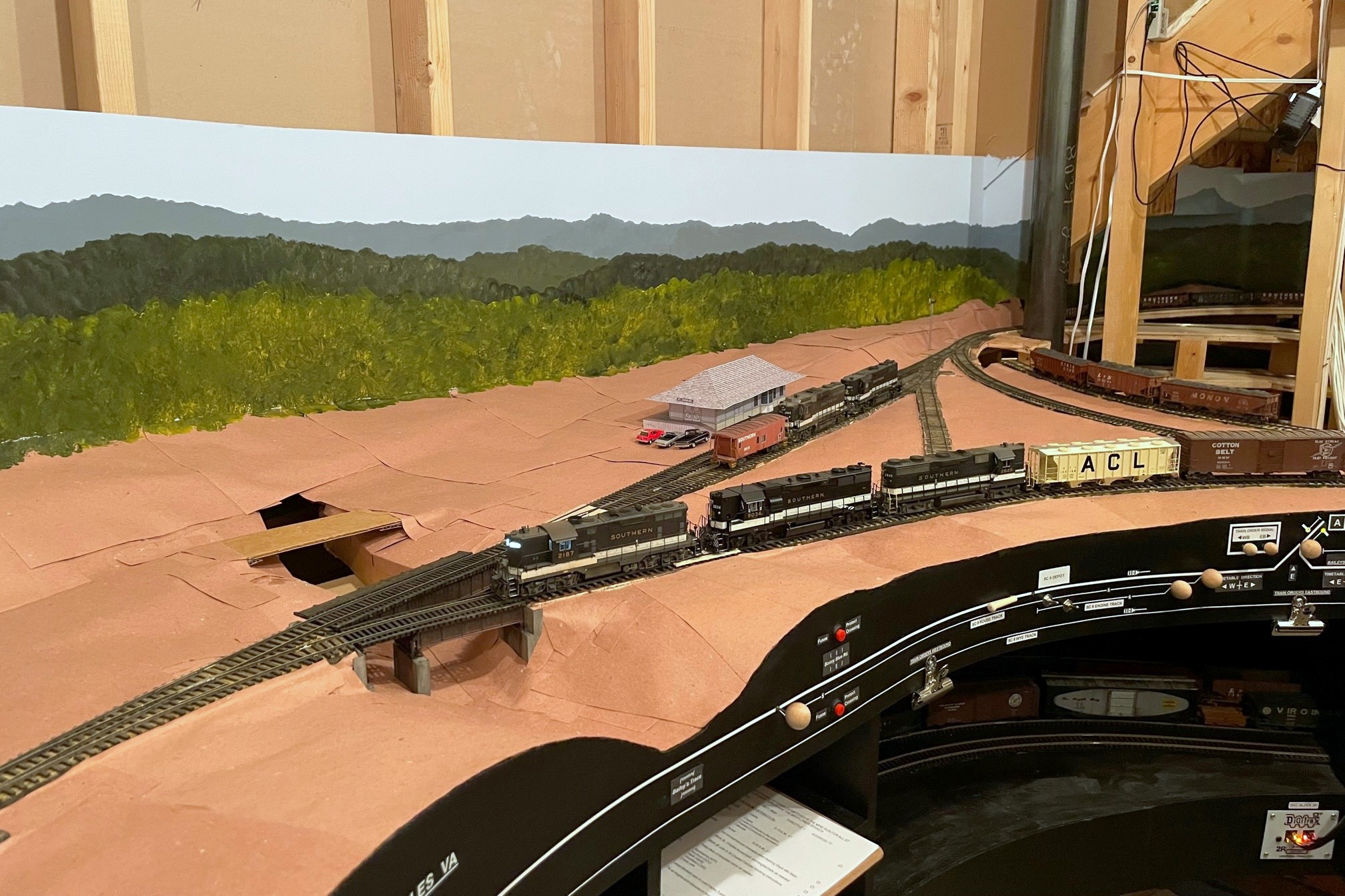
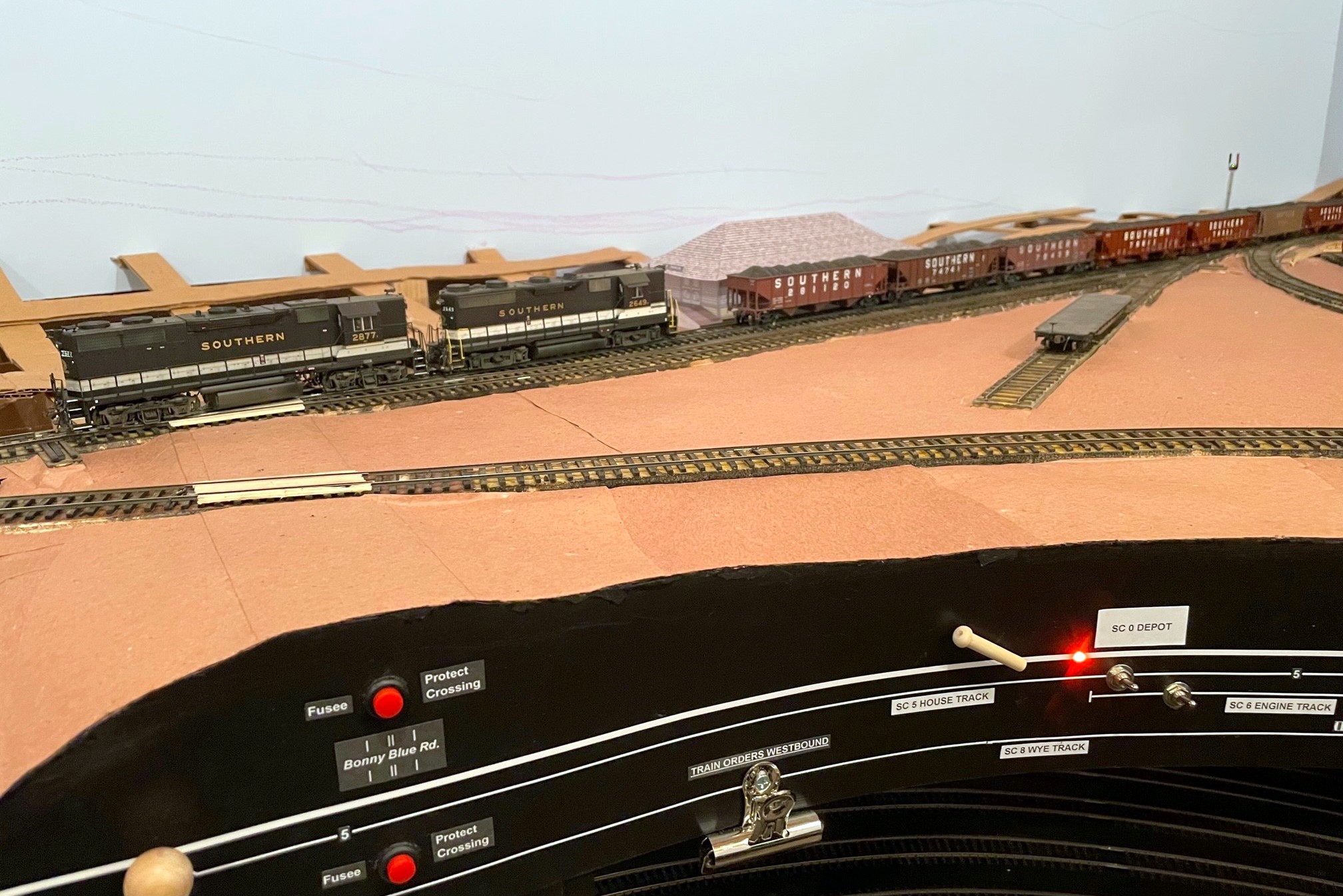
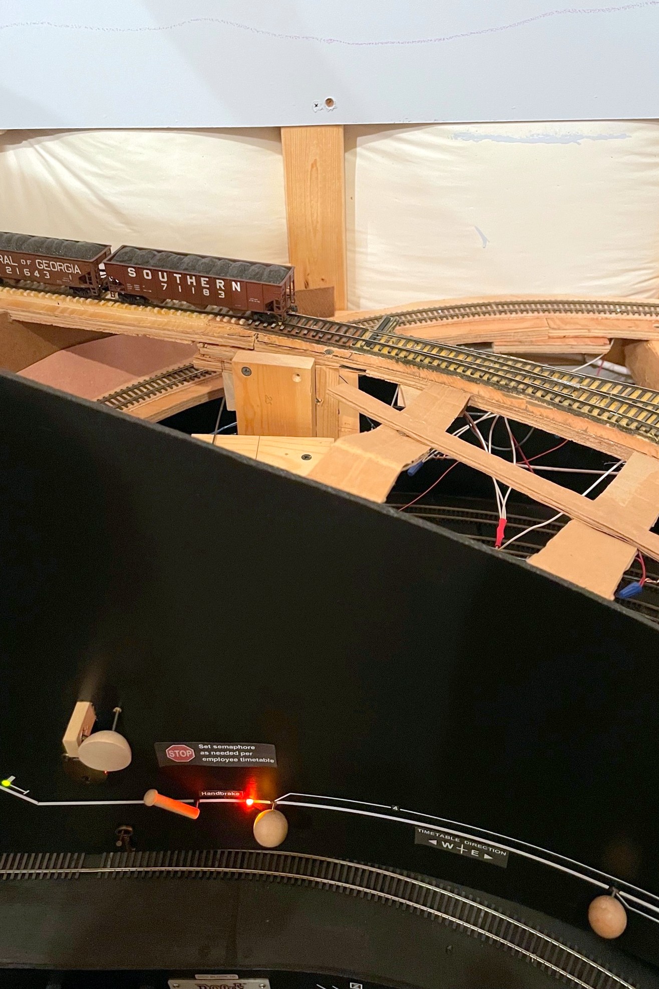
The St Charles Switcher crew sets the handbrakes to leave a string of loaded hoppers on the grade while working the yard
Gravity is a major factor in prototype railroading, but it can be quite troublesome for a model railroad. Very little real track is actually completely flat, so train crews routinely use the handbrakes on individual cars to hold them in place in yards or sidings. Not only do handbrakes hold cars in place, but in the Appalachians where I model, gravity and handbrakes were often used to move cars from empty tracks to tipple loading points, to move loads into the right track below the tipple, or even to run-around a caboose at the end of the line. Modeling working handbrakes on individual cars isn’t very practical, so what is a model railroader to do? Some install springs on the ends of a car’s axles to use friction to hold the car, but this can’t be “turned off” to allow the car to roll freely. Others use little picks they stick into the ballast to hold cars in place, but this can be destructive to scenery, and it leaves an un-prototypical giant stick next to a cut of cars. I’ve adopted a method of fascia-controlled “handbrakes” on the tracks which works well for my needs.
The first step of the handbrake is to locate where you want the brake, drill a hole, and insert a brass rod sleeve for the brake wire
This method is overkill if you just want to hold cars in place on a siding. For this I recommend a drop of CA, a piece of monofilament line sticking up through the tracks, or the end of a soft brush if more strength is needed–I use all of the above for holding cars in place when set out. I use the method here where I need brakes sometimes and free rolling other times, so the first thing you need to do is figure out where you need brakes. I once heard a story about a design presented to a university for a new campus that didn’t show any sidewalks. When the dean of the university asked the designer why there were no sidewalks, the designer replied “wait a year after the campus is open, then you’ll know exactly where the sidewalks need to go based on the trails through the grass.” So, where do I install brakes? Wherever I find I need them when operating trains–a question I also pose to my operators after every session: “is there anywhere you wished you had handbrakes but didn’t.” Generally speaking, they’re needed anywhere a crew will need to leave cars on a grade for a period of time to conduct other work. Since I’ve got lots of grades on the layout, I’ve currently got five handbrakes installed on the lower level alone.
The concept of these fascia-controlled handbrakes is simple: install a movable piece of strong wire between the rails tall enough to hold an axle with a mechanism to retract it when not in use. Once you know about where you need brakes, mark that spot between the rails, and make sure the area underneath is clear enough to install a brake mechanism. Remember, the brake can really be anywhere along a string of cars, so if your ideal spot is not to ideal under the layout or on the fascia, just move it a few inches. I use 1/16″ brass tube as a protective sleeve for the .025″ steel music wire I use as the brake, so once I find a spot, I drill a vertical hole between the ties for the brass rod. I like to offset the rod about 1/4-1/3 between the rails to avoid interfering with truck bolsters (coupler trip pins will also be an issue for those who use them… in fact, a similar mechanism might work for uncoupling too, hmmm…).
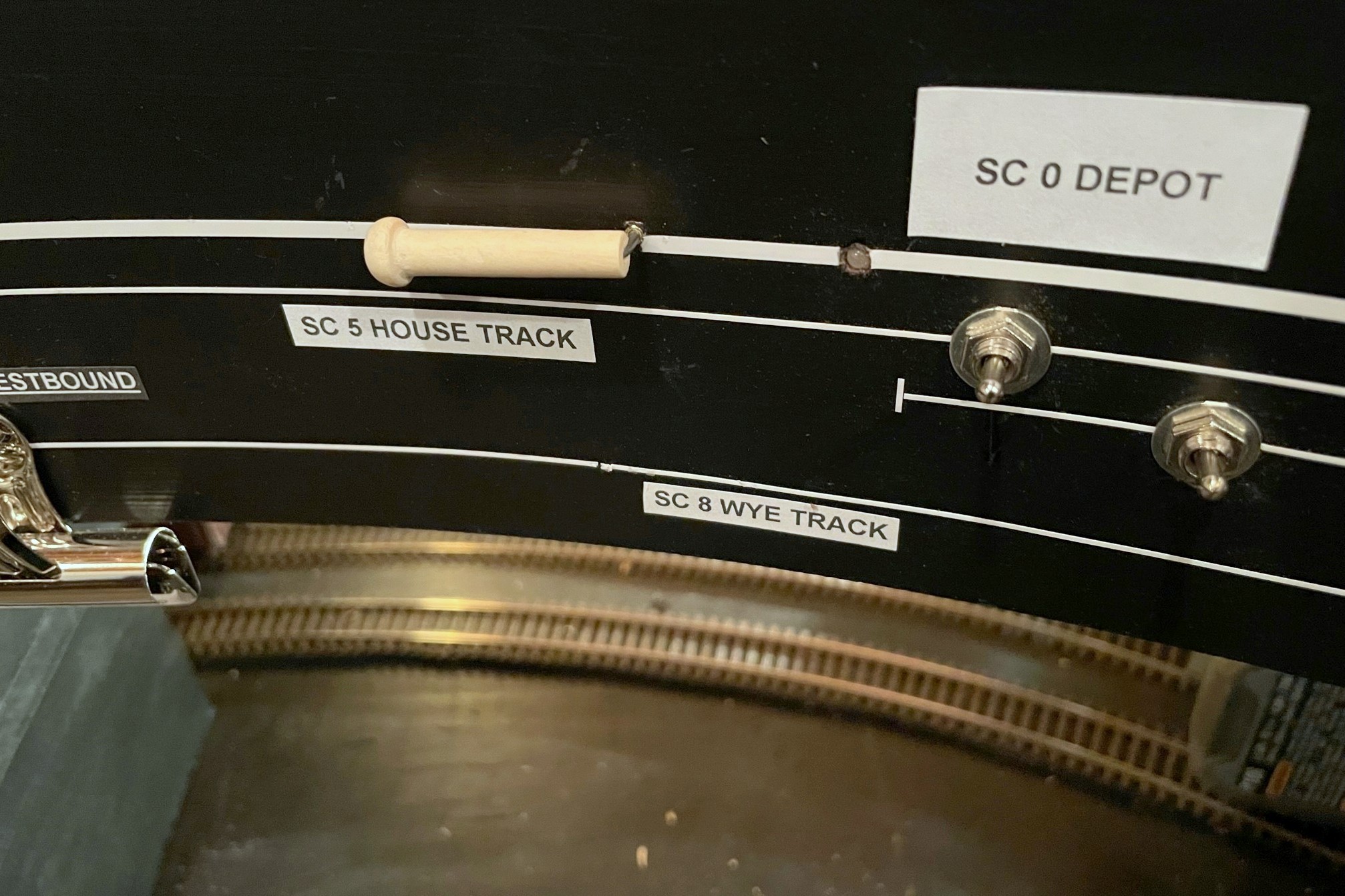
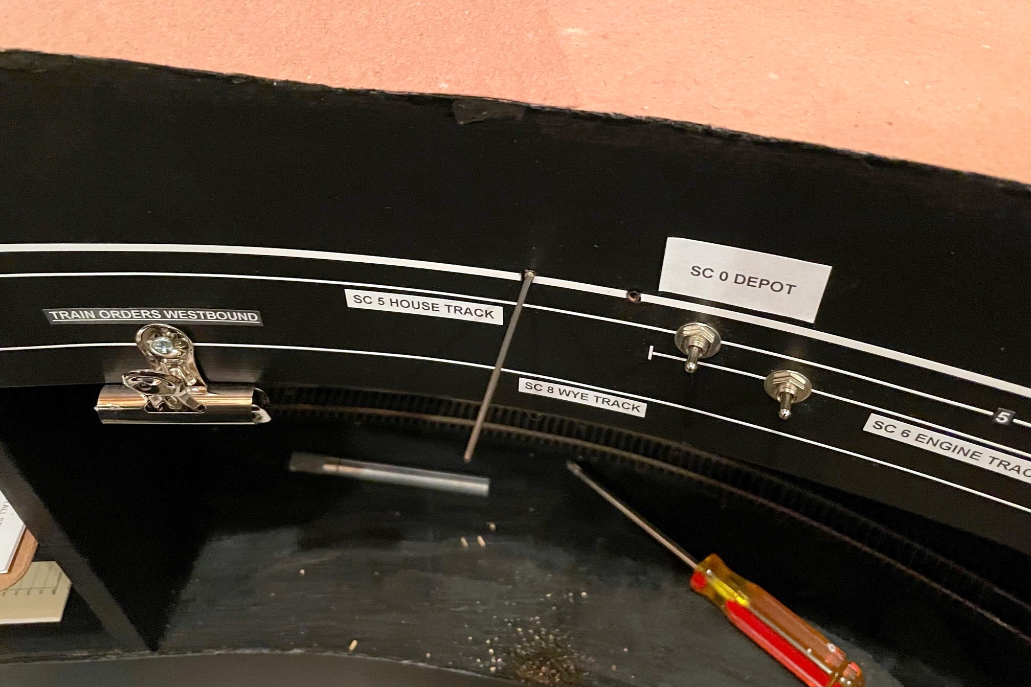
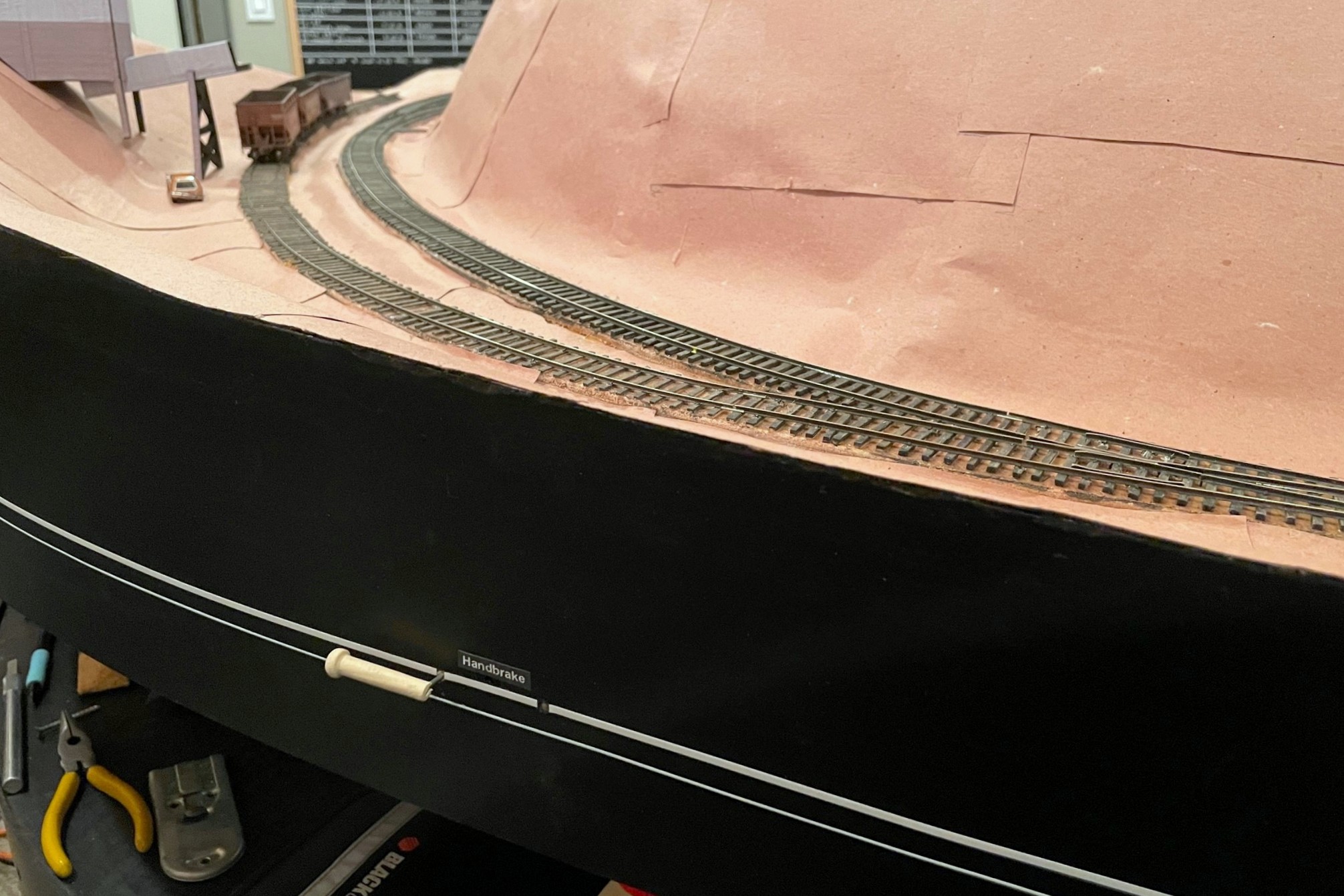
Here’s the finished control in the “off” position (in line with track)
If you’ve followed me for a while, you know I’m a big fan of manual controls using slide switches–I use them for turnout controls, semaphore controls, and now handbrakes. You also know I’m a stickler for creating a fascia where the controls make sense and aid an operator instead of confusing them. In the case of the handbrake, I wanted it to be easy for operators to see when the brake is “set” and when it is retracted, so I settled on a control lever that lies in-line with the track when retracted and sits at a sharp angle when “set.” Just for good measure, I also use a bi-color LED to illuminate amber on the fascia representation of the affected track when the brake is set to help mitigate inadvertently running into a brake with the delicate footboards of a super-detailed locomotive (been there, done that).
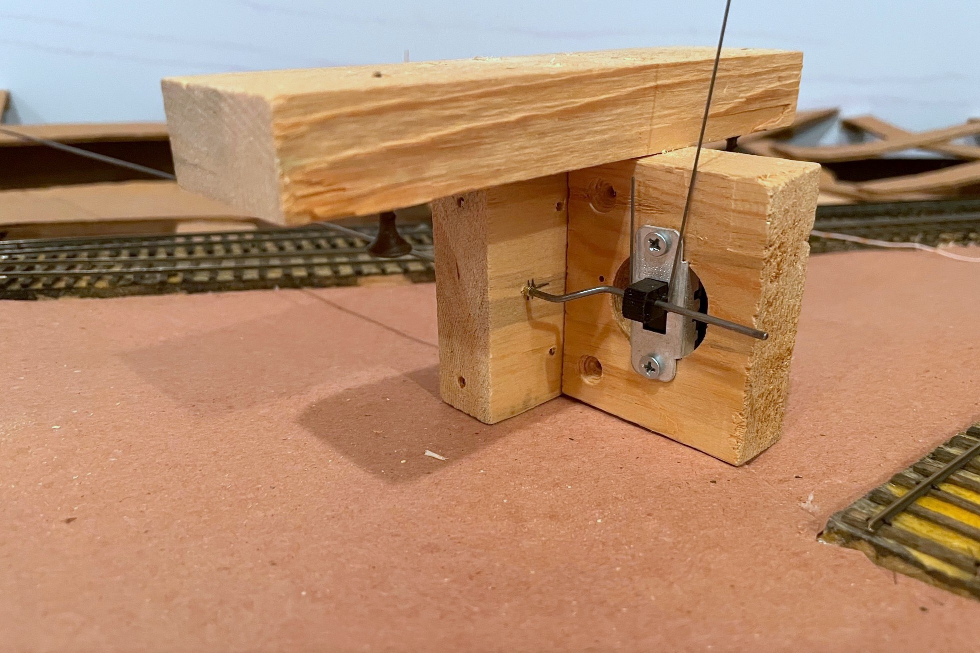
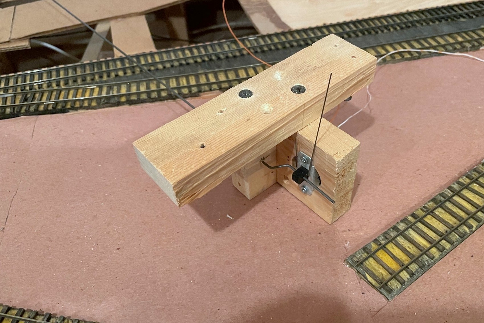
Here’s the completed brake assembly with three pieces of wood, DPDT slide switch, brake wire (vertical), and control rod (horizontal)
For the brake mechanism, I use a vertically mounted slide switch (DPDT in this case) with a 3/16″ throw–this is just enough to catch the axle of a 36″ wheel in HO scale when extended and still retract to almost rail height when recessed. The brake rod itself is a piece of .025″ music wire bent into a squared-off “J” shape running through a hole in the slide switch–initially, make this piece long enough that it will stick up about 1/2″ or more above the rails when in place. The control mechanism is a piece of thick steel rod (.062″ music wire) with a bell crank bent at one end. Th rod should be cut about 3″ longer than the distance between the brake’s track location and the location of the control on the fascia. The bell crank is offset about 1/4″ from the rod. As you can see in photos, I drill a hole in a piece of 1×3″ board centered on the slide switch and offset about 1/4″ laterally for the control rod to pass through (lined with 3/32″ brass tube for smooth operation). I also bend the bell crank at 45-degree angles instead of 90 as this allows me to make adjustments to the crank offset in either direction, shorter or longer. The structure for the mechanism is typically three boards: 1) the slide switch board with a large hole drilled out for the switch (mounted with screws), 2) the control rod board mounted 90 degrees to the switch where the bell crank is secured, and 3) the attachment board on top to make it easy to mount to the plywood sub-roadbed. I use 1×3″ pine for most of my pieces, but I may use different thicknesses of attachment plates to get the control rod at the right height for the fascia control–the brake wire can be really tall and still work, so better to have the mechanism hanging lower than to have to curve the control rod to the right height. Once I’ve got the three boards assembled with 1 1/4″ drywall screws, I disassemble it, insert the bell crank end of the control rod, insert the bell crank into a hole drilled in the slide switch, adjust the bell crank as needed for smooth operation of the switch, and reattach the boards with the screws.
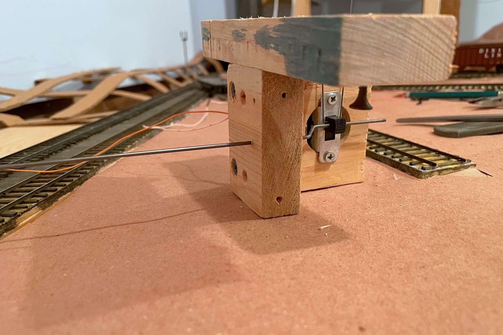
The left is the front side of the assembly that will face the fascia–note the brass rod sleeve in the wood where the rod goes through
For the fascia, I drill a hole for the 3/32″ brass rod sleeve as close to horizontal as I can get it and pointed directly at the brake location on the track. I pick the spot on the fascia that allows me to do this while keeping the control rod as perpendicular as possible to the fascia (you don’t want the control rod coming out of the fascia at a strange angle if you can help it). The LEDs are nice but not necessary, but this is the step where I drill the holes, about 1″ behind the brake control. I like to drill the hole through the fascia the exact size of the LED bulb and then use a second larger bit from the back side of the fascia to create a space for the rest of the LED–this keeps the LED from popping out the front of the fascia. I use bi-color red/green LEDs which glow a nice reddish amber when hooked up to AC (e.g., DCC track bus), and I attach one lead to one side of the track bus (with a 470K resistor), the other lead to the “up” position of the slide switch, and a third wire from the center position of the slide switch to the other side of the track bus. Super simple.
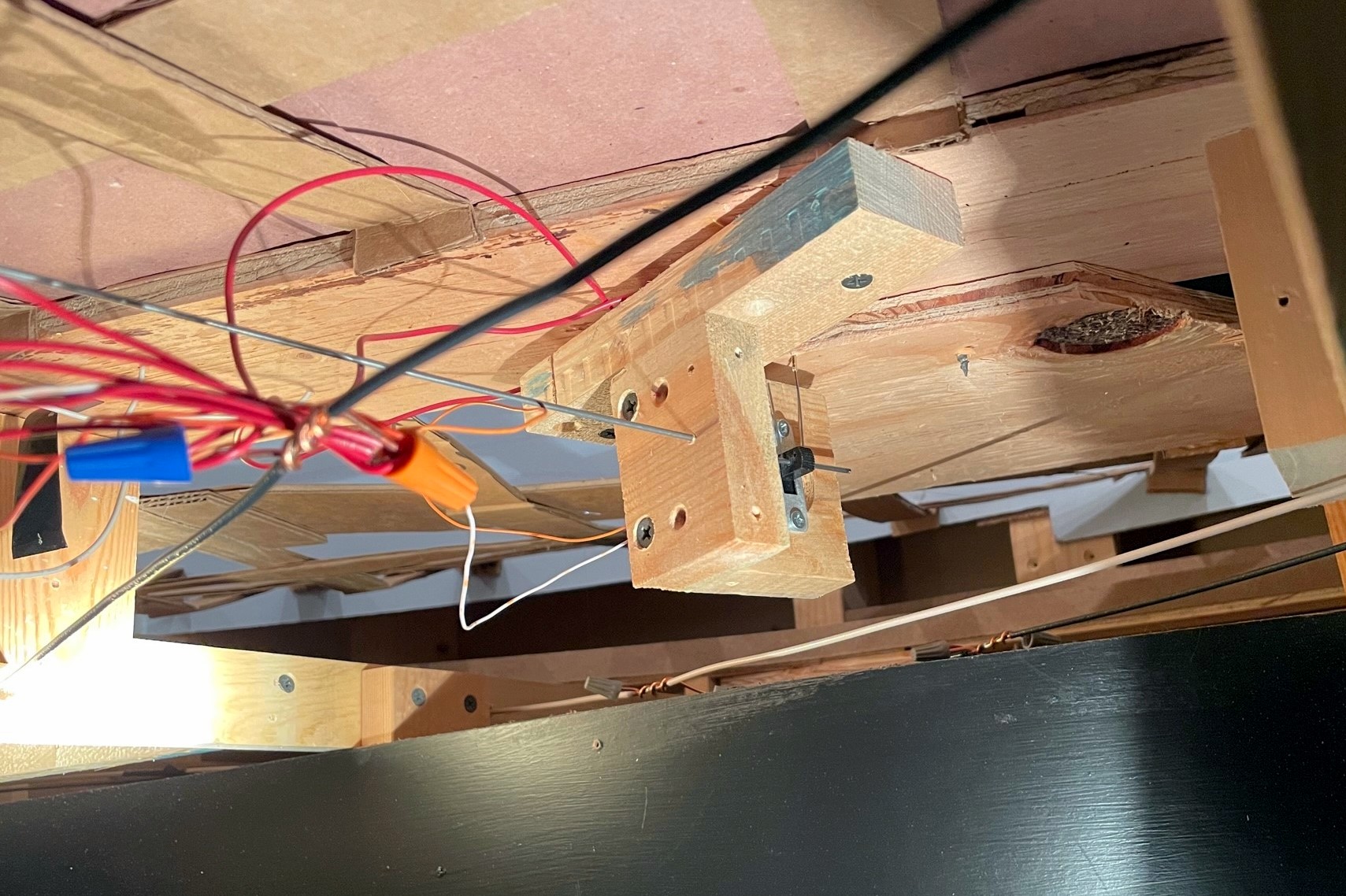
Here’s the handbrake mechanism installed under the layout–the control assembly should orient to the fascia and not the track
Mounting the switch mechanism is a bit of a pain and requires some planning and patience. From under the layout, I run the control rod through the fascia. Then I find the brass rod going up through the tracks and insert the brake rod (it helps if the brass rod is long enough to protrude beyond the plywood of the sub-roadbed). With the mounting screws on the attachment plate ready to go (screwed in so they’re almost through the board), I gently move the mechanism around until the brake wire is more-or-less vertical, the switch operates freely, and the control rod is as straight as possible between the fascia and mechanism. The mechanism is oriented to put the rod and switch perpendicular to the FASCIA rather than the track (angle relative to track doesn’t matter here). Once I’m happy with the placement, I run the mounting screws into the sub-roadbed.
With the brake in the RECESSED position, bend the control rod parallel to the ground
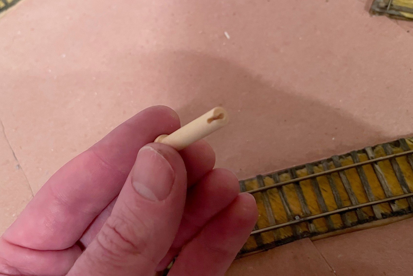
On the fascia side, I now have about 2″ of control rod sticking out. With the slide switch in the DOWN position, I then grasp the control rod with a pair of needle nose pliers flush with the fascia so the bend will be about 3/16″ from the fascia and use my hand to bend the control rod to align with my track diagram (horizontal) in the direction of the bell crank so that “up” on the control = “up” on the brake. My convention is to face the controls and bell cranks to the left, but either works. At this point, I have the leverage to test the mechanism and fix any issues. If all is good, I use a Dremel cut-off wheel to cut the end of the control rod so about 3/4″ beyond the bend. For the control lever, I use a wooden 1 3/8″ “axle peg” which can be found at any large craft store–it’s admittedly an odd shape, but it’s distinct, easy to find, and easy to use. I insert the pegs into a vice and drill a hole the exact size of the control rod about 1″ deep into the center of the peg, then drill another hole in the side about 1/8″ from the flat end into the first hole and use an X-Acto blade to create a notch between the two for the 90-degree bend in the control rod. The peg is usually a press fit onto the control rod.
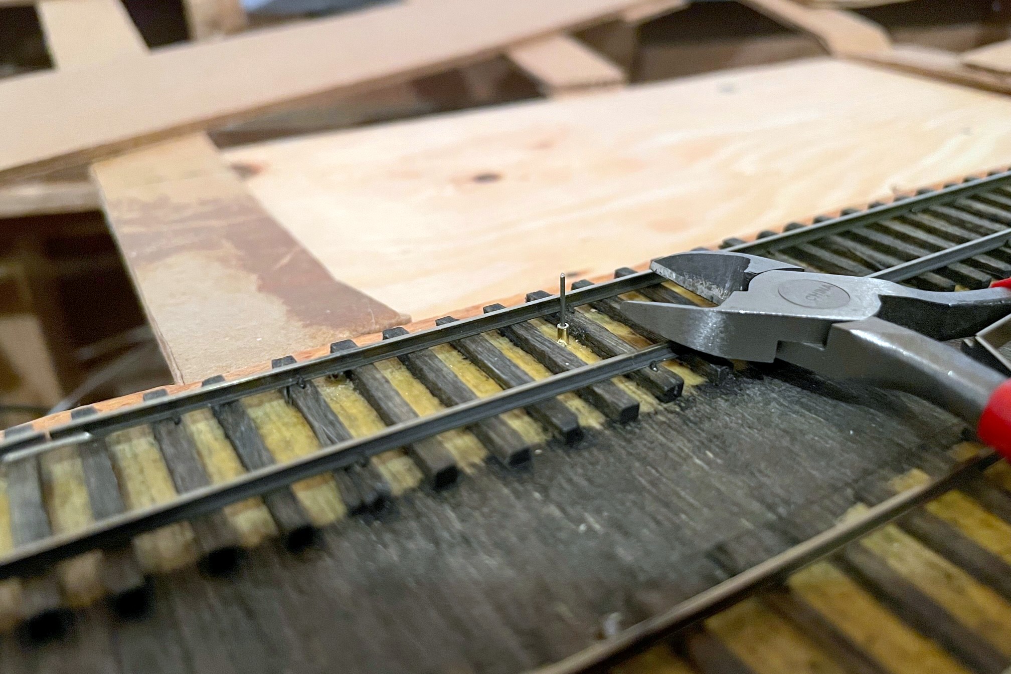
The brake wire should initially be longer than required in the recessed position
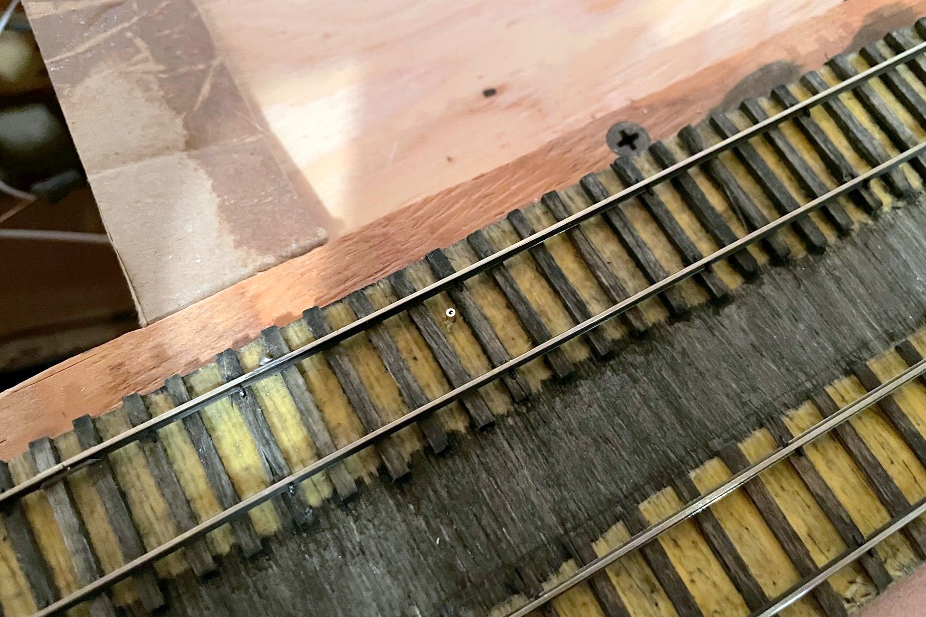
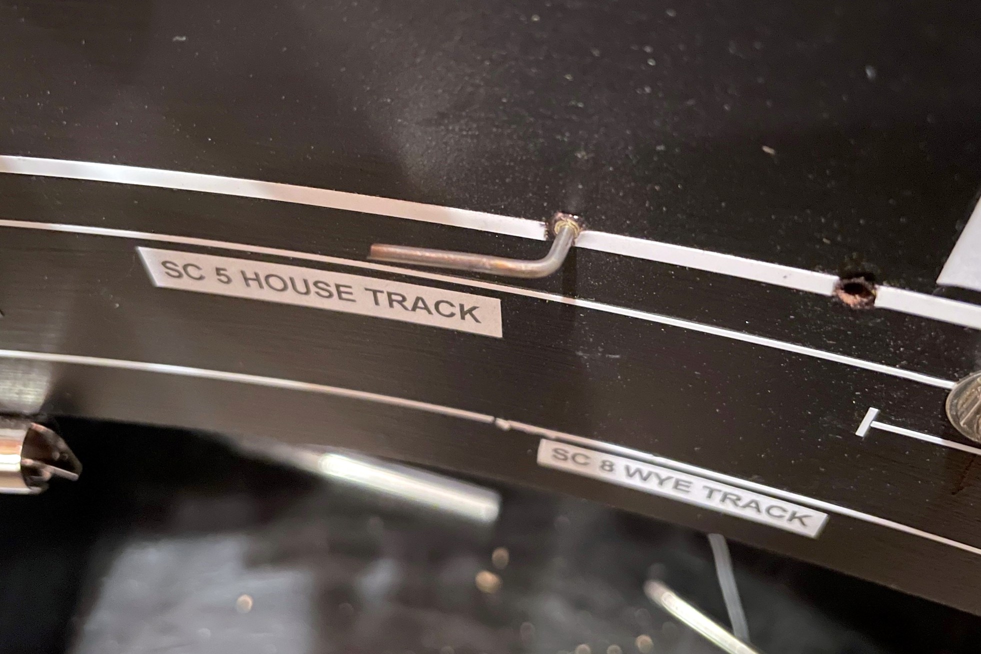
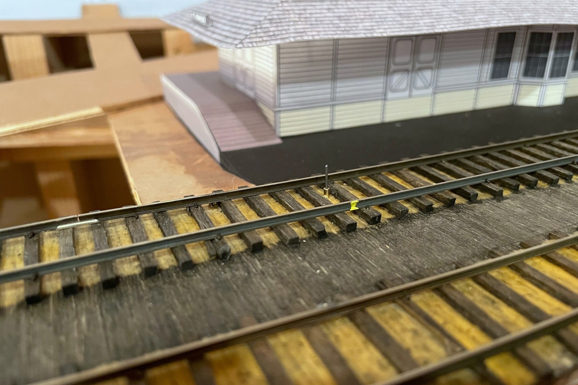
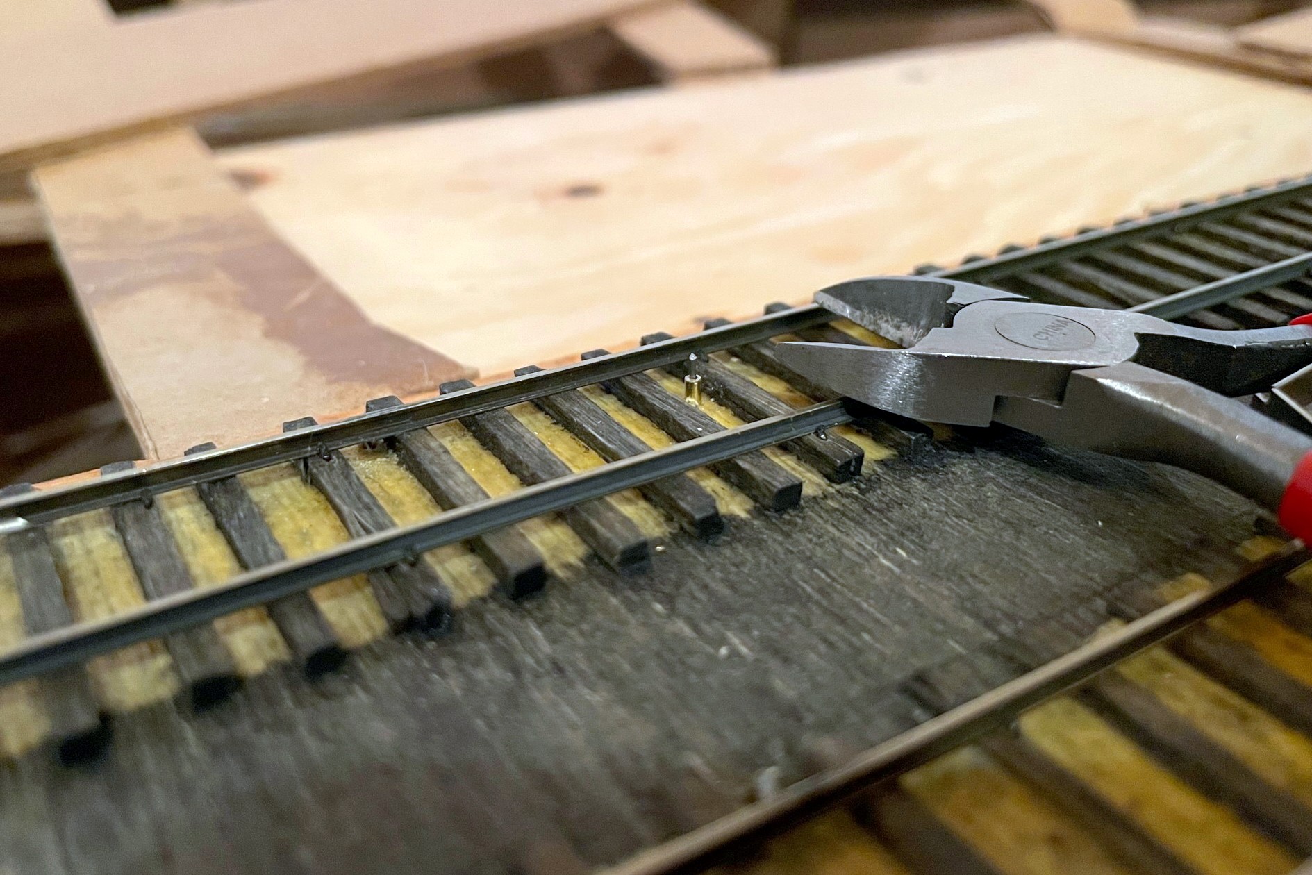
The final step is to trim the brake wire. I’ve found if I use a pair of wire cutters at rail-top level when the brake is in the DOWN (recessed) position, it is low enough for all my locomotives to clear and extends high enough to catch all my axles when needed. Because the wire’s location can be tough to see (especially when cars are over it), I use a little dab of yellow paint on the outside of the rail to indicate where the brake wire lives for easy spotting by crews.
The brake wire can be tough to see with cars on top of it, so I use a little dab of yellow paint on the rail to help operators know the brake location
I’ll also share some “lessons learned” for using this type of handbrake:
The brake will find your lowest-clearance locomotive and keep it from moving until you trim the brake wire–remember this locomotive and use it to test all brake installs
If you try to pull a string of cars when the brake is engaged, you WILL bowstring every car between the locomotive and the brake off the rails (sometimes violently)
If you leave the brake “up” and roll cars into it, they will bounce back quite jarringly upon hitting the brake
If you don’t pay attention and activate the brake under a truck bolster or low-hanging part of the car, you WILL raise the car off the rails and derail it (or topple it)
Other than these “gotchas,” I’m very happy with the operational possibilities these handbrakes add to the model railroad!
The St Charles Switcher crew sets the handbrakes to leave a string of loaded hoppers on the grade while working the yard
The first step of the handbrake is to locate where you want the brake, drill a hole, and insert a brass rod sleeve for the brake wire
Here’s the completed brake assembly with three pieces of wood, DPDT slide switch, brake wire (vertical), and control rod (horizontal)
The left is the front side of the assembly that will face the fascia–note the brass rod sleeve in the wood where the rod goes through
Top view of the handbrake assembly–the top board helps to mount the assembly securely under the subroadbed
Here’s the handbrake mechanism installed under the layout–the control assembly should orient to the fascia and not the track
The control rod should protrude through the fascia at least 2″
With the brake in the RECESSED position, bend the control rod parallel to the ground
I use a wooden axle for the control rod and drill out a hole the size of the control rod along with a notch on one side
Here’s the finished control in the “off” position (in line with track)
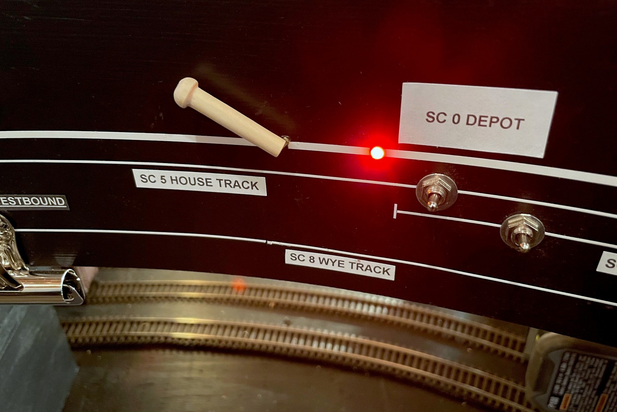
Here’s the handbrake control in the “on” position–the LED helps alert operators that the track is not clear
The brake wire should initially be longer than required in the recessed position
With the brake wire in the recessed position, trim it to just above rail height with wire cutters
The brake wire can be tough to see with cars on top of it, so I use a little dab of yellow paint on the rail to help operators know the brake location
Here’s another handbrake on the main at a location where crews have to leave their train to work cuts of cars through a short run-around just ahead
Here’s another handbrake on a 3 percent grade above St Charles Yard–I use this one to set cars above the yard and use gravity to route them down the right track, just like the prototype would often do
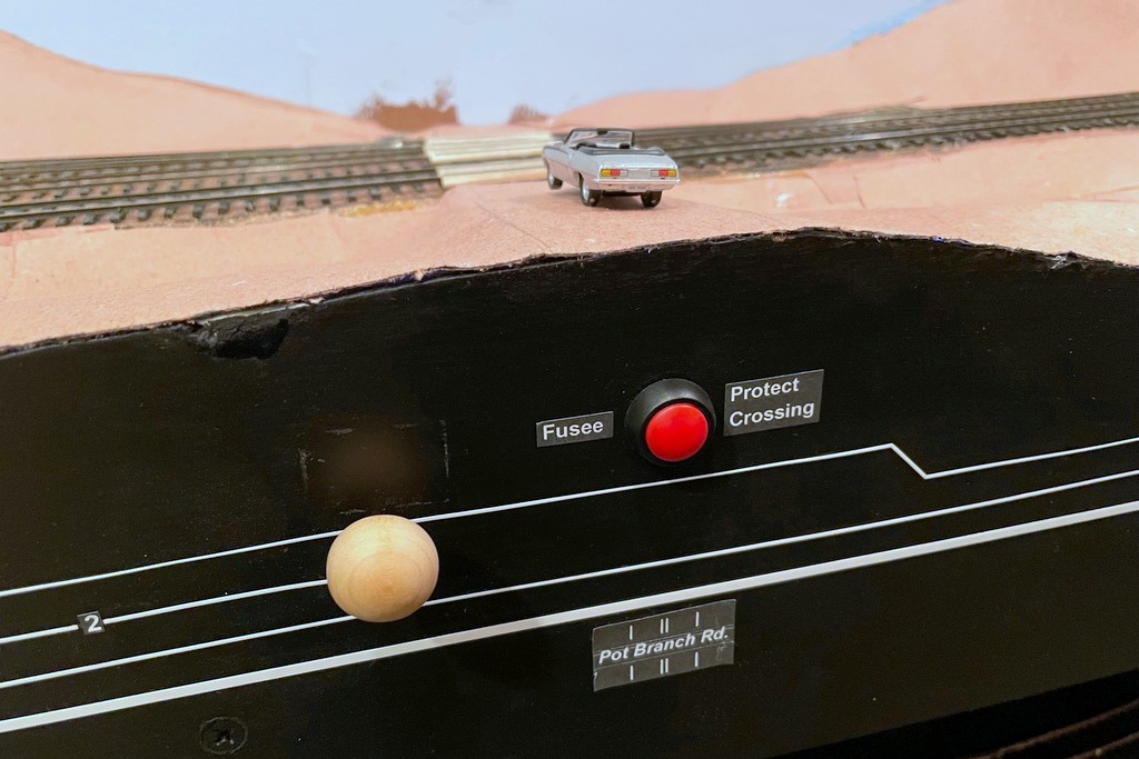
The St Charles Switcher crew throws down a couple fusees to protect the Pot Branch Road grade crossing near Mayflower
I enjoy trying to copy every element of prototype railroading I can… as long as there’s at least an element of fun in it. When I saw this short video showing a Western Maryland crew dropping fusees (pronounced “fyoozees”) to protect a grade crossing, I started thinking about how I might model this. Fusees are used by railroads for many purposes including dropping them on tracks to warning following trains of their presence–because of this purpose, fusees are designed to burn for a set time, commonly 10 minutes. Fusees can also used to protect grade crossings that don’t have flashing lights like the one in the WM video, especially when it’s dark or posting a flagman wouldn’t be practical or safe. Since I want to model nighttime ops, and I haven’t made any HO scale flagmen to post yet, I decided I wanted some simulated fusees to protect the handful of crossings I have on the layout.
My first attempt was pretty simple and economical, just two fiber optic cables embedded into the “road” (it’s just paper and cardboard at this point) on either side of the grade crossing routed to a bi-color LED that I connected to the DCC track bus (creates a reddish orange glow) and a simple SPST push-button switch. To keep the fiber optic cable from falling through the road, I melted the end into a mushroom shape by holding it near a hot soldering iron. The other ends were taped together and inserted into a piece of shrink tubing around the LED. It was functional enough to protect the crossing, but I really wanted a way to 1) put the fusees on a timer, and 2) make them look a little more realistic.
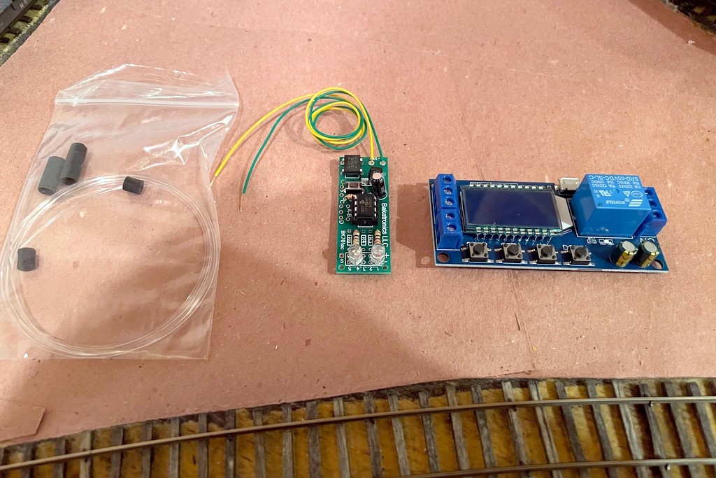
The basic parts to make a simulated fusee including fiber optics, the Bakatronics flares / fusee circuit, and the timer circuit
The timer issue was solved by searching Amazon and looking at a lot of different timing circuits. I finally settled on this one, though it’s probably overkill. I like it because you can choose one of several timing modes (fun to play with for other projects), you can set the timer for however long you want to keep the relay “on,” and you can easily see the timing settings on the display. To make them more realistic, I started with an internet search for “model railroad fusee,” and after chasing through some links in model railroad boards, I discover the Bakatronics BK-111 “Simulated Flares / Fusees Kit.” It looked promising, especially since it’s designed to power two fusees that “light” and extinguish several seconds apart (like one person is walking a short distance between lighting them, just like a grade crossing). I ordered two just to make sure it would work, and I was not disappointed! When activated, they “light” at different times, flicker independently for a while, then the first one goes out, then the second with a nice slowly diminishing burn out… really cool looking!
The fusees are controlled with a simple momentary SPST switch on the fascia
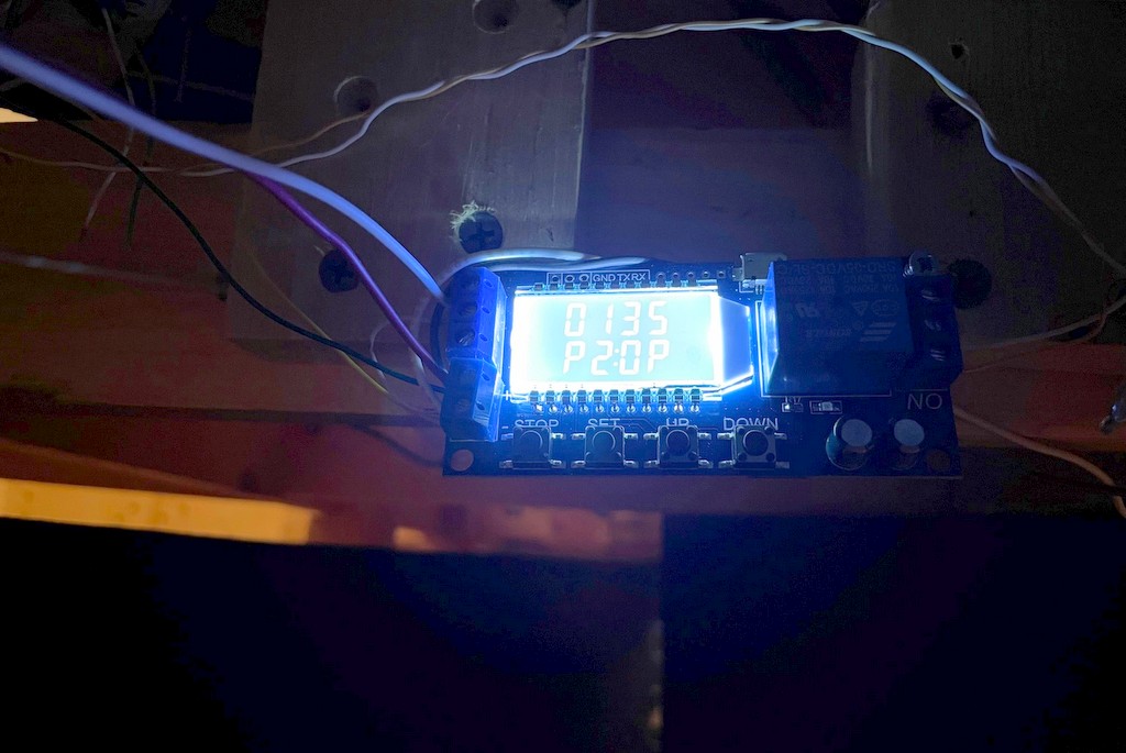
The Bakatronics fusee circuit is designed to work with either a momentary switch (stays on for about 30 seconds) or an on/off switch (stays on as long as the switch is closed). Instead, I wired the fusee circuit to the timer circuit so I could set the time the fusees stay lit exactly, and all the operator has to do is push a button once. I use a 4:1 fast clock, so a 10-minute burn should last about 2.5 minutes / 150 sec. The Bakatronics circuit add some time on its own, so I found a setting of 135 sec on the timer keeps the fusees lite for about 10 scale minutes, and like the prototype, the crew only needs to worry about whether or not to put down another set of fusees (push the button again) if the first set “burn out.” Both the timer circuit and fusee circuit run off a ~12V DC bus I have running around the fascia, previously to power semaphore lights. Here’s a video of the fusee in action…
We used these on my last operating session, and I thought they added a neat bit of prototype thinking for the crews–we had to think about protecting the crossings while moving the trains, and the flickering fusees gave a visual representation of the action taken. I can’t wait to try them at night when I’ve got the final lighting installed!
The basic parts to make a simulated fusee including fiber optics, the Bakatronics flares / fusee circuit, and the timer circuit
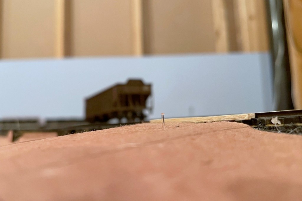
Here’s the end of the fusee pulled out of the “road” for better viewing… just the end of a fiber optic cable melted into a mushroom shape
Here’s the powered timing circuit showing mode “P2” (reset time if pushed again) and “135” second of “on” time once activated
The fusees are controlled with a simple momentary SPST switch on the fascia
A look at the glowing fiber optic cable under the layout that lights the fusee
The St Charles Switcher crew throws down a couple fusees to protect the Pot Branch Road grade crossing near Mayflower
The layout’s not set up for night operations yet, but once it is the fusees will look spectacular!