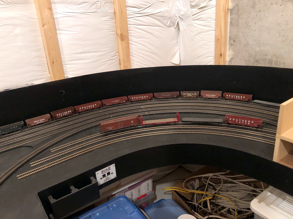
L&N RS3 100 takes a trip around the wye at St CharlesCompleted St Charles yard tracks
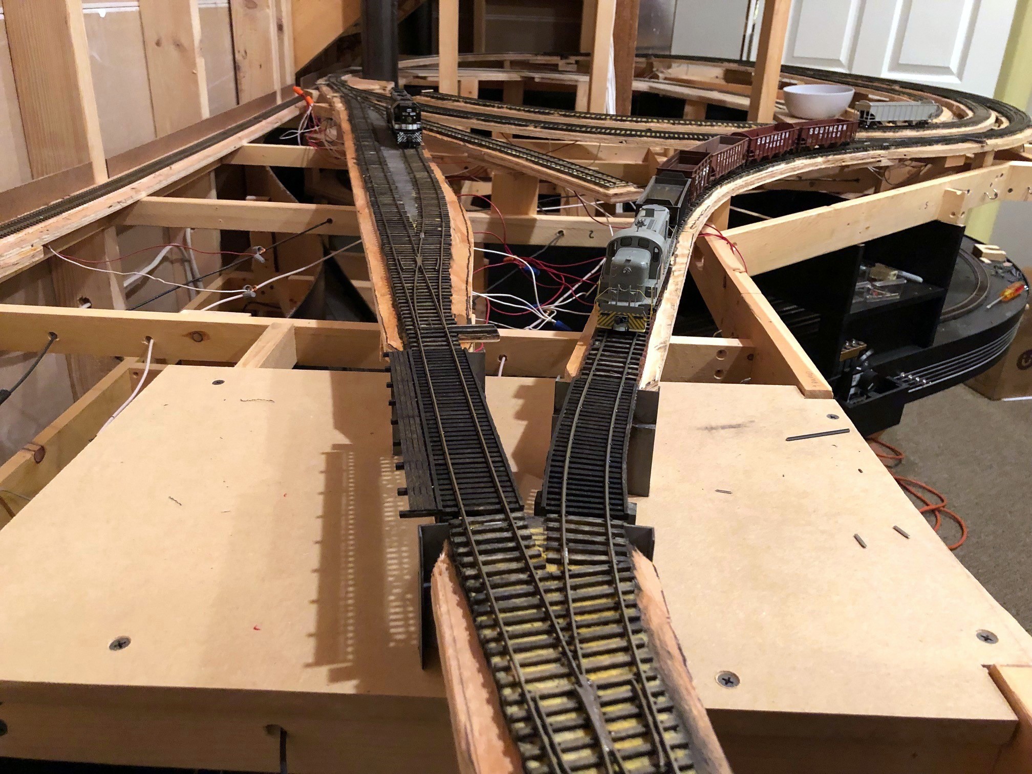
Hit a major milestone yesterday: the lower level tracks are complete! I completed the first scene, the end of the line at the Mayflower tipple, several months ago, and the last few months I’ve been working on the long scene at St Charles. St Charles – the branch’s namesake – was home to a wye, a depot, a couple small tipples, and a three-track “yard.” St Charles was also home to a mine run when the tipples were busy, so this is the central scene on the layout. All told, the St Charles scene is about 26 linear feet long and required 14 hand-laid switches (about 1/2 of them curved) and a couple of bridges.
Electrically, I made the entire Mayflower branch an auto-reversing zone for the wye. Can I just say the On-Guard AR solid-state DCC auto-reversers are awesome? The switching of polarity on the wye is absolutely seamless and unnoticeable–I highly recommend them! I also isolated a single rail of both the “house track” and “engine track” in the middle of the wye and will place a switch on the fascia. This will allow me to turn the power off to the two tracks that would hold idling power in case any sound locomotives get annoying. Next step is fascia and switch controls.
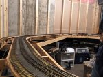
This is the current “end of track” just above the St Charles yard
L&N RS3 100 takes a trip around the wye at St Charles
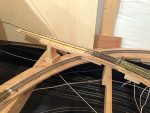
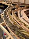
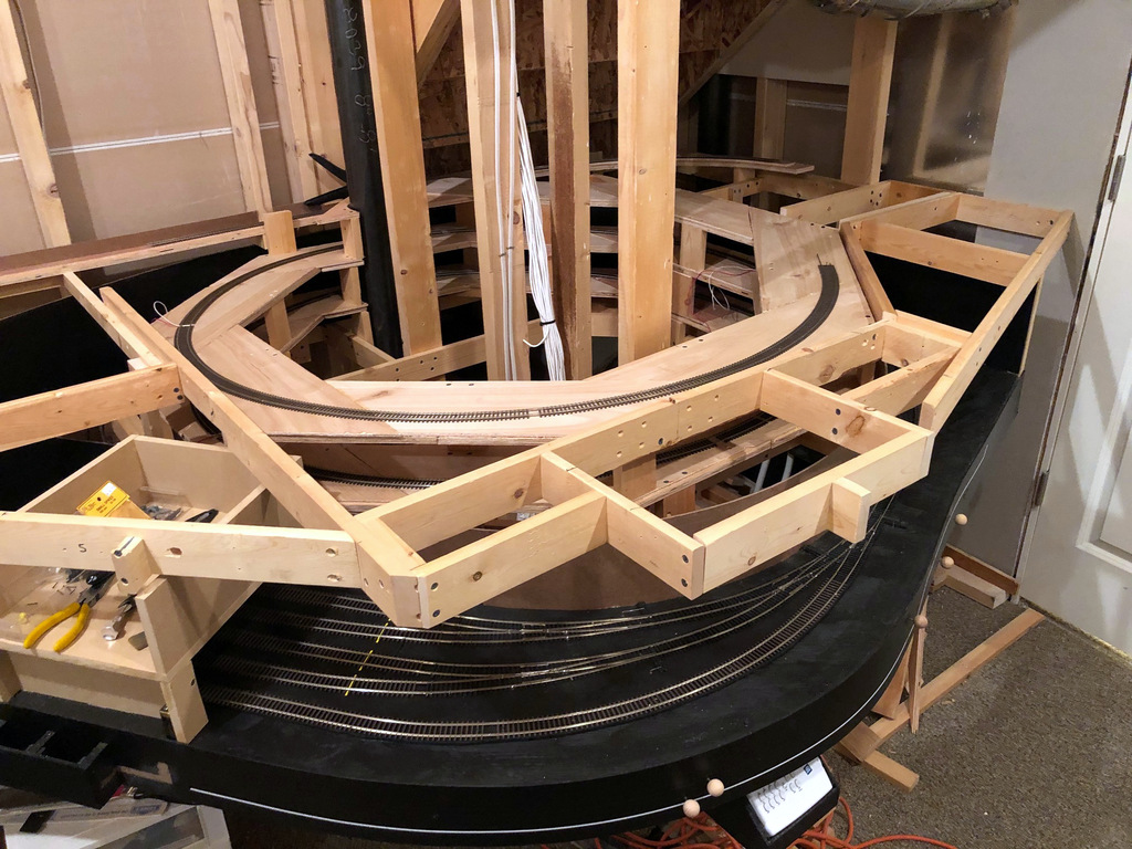
Overview of the Mayflower leg of the St Charles wye
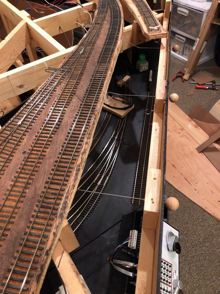
Celebrated something of a mini golden spike this week. I completed the mainline track for the Mayflower leg of the wye in St Charles. With this bit of track installed, trains can finally run up from the staging level and to a tipple (Mayflower). It’s not much in the grand scheme of things, but its a milestone nonetheless. Next will come the Monarch leg of the wye with its house track and engine track followed by the two yard tracks above the wye. Getting pretty close to having all the track on the main level installed.
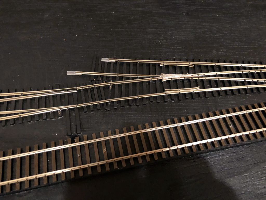
I learned a good lesson on hand-laying track. The frog needs to be electrically isolated by cutting the rails on either side of the frog. To keep the frog and rails aligned, I spike both sides of the cut before cutting. When I wired everything up and applied track power the first time in this new section, it immediately shorted out. I could hear a soft click coming from one of the switches. Usually this means one to three things 1) I wired a feeder to the wrong bus, 2) my cut didn’t make it all the way through or 3) the point rails somehow slid back together with the frog. A check of all three of these things was good, but when I dropped the feeders from the point rails, the short cleared–it was still somewhere on this switch. After a few minutes of jiggling random things and staring at the problem, I finally figured out that two of the spikes that were holding separate point rails down near the frog cut were touching even though the rails weren’t. Go figure, metal spikes attached to metal rails conduct electricity… a quick repositioning of one of the offending spikes did the trick.
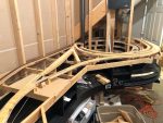
Track laying in progress on the Mayflower leg of the St Charles Wye
Overview of the Mayflower leg of the St Charles wye
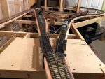
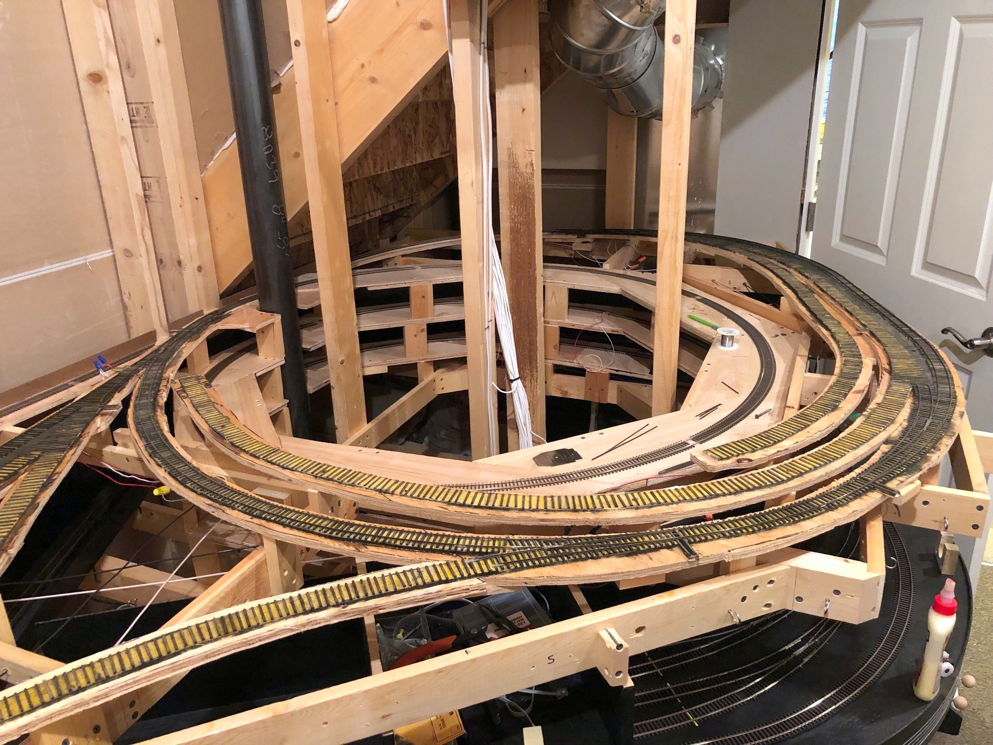
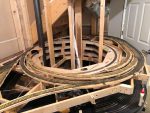
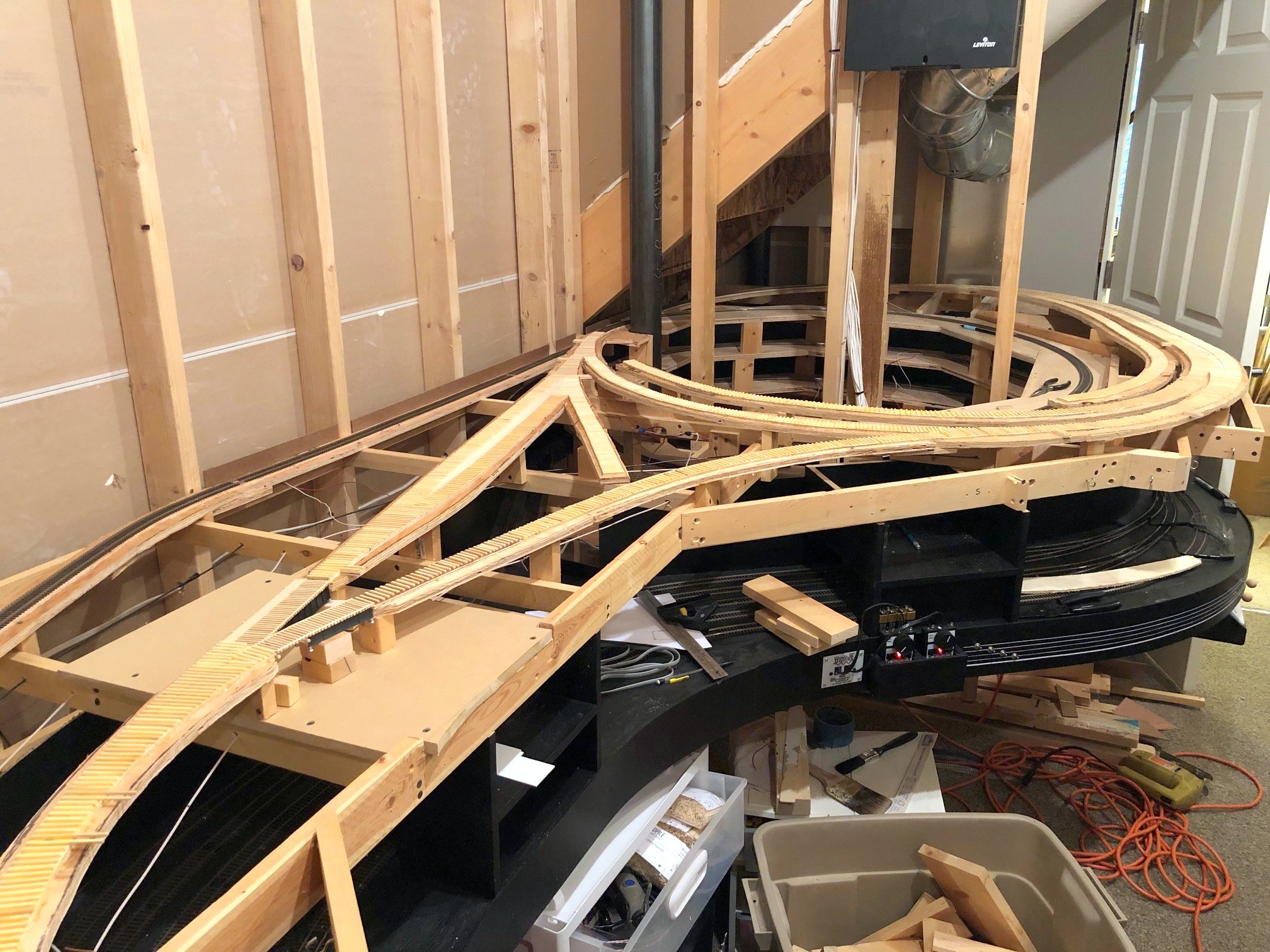
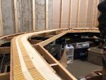
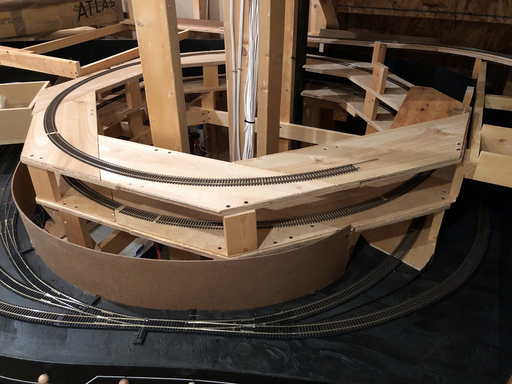
Overall view of the wye at St Charles including the house track and engine track inside the wye and the bridges over Bailey’s Trace
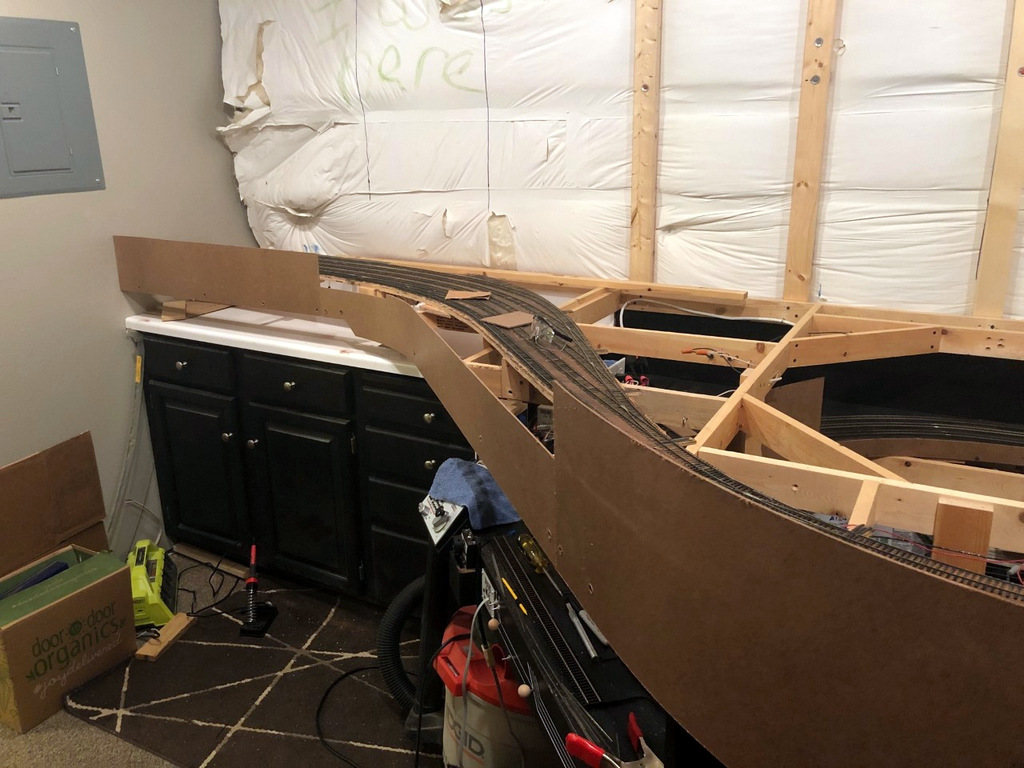
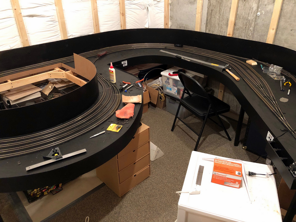
After a nice and productive summer focusing on building models (thank you St. Louis RPM meet for the motivation), I’ve returned to working on the layout. The next step is a big one, the scene of St. Charles, VA. This is the central scene of the entire layout. This is where trains emerge from staging, the site of the local station and engine tracks, the small yard for the branch, and the wye taking trains either up to Mayflower or Kemmergem, Monarch and Benedict. While I could have modeled these tracks in pieces, I decided to do the entire scene at once to avoid further stalling and to limit the need for multiple coats of stain on the ties (takes forever to clear out the smell!).
I’m using basic cookie cutter construction. I lay down 1/4″ door skin ply and draw out the tracks using templates and a piece of flextrack with thumbtacks to hold it in place. After cutting the upper subroadbed, I then trace the pattern only 1/2″ plywood staggering the seams. For this scene, I cut out all the 1/4″ ply to make sure everything fit, then cut the thicker ply. Construction so far is proceeding according to the plan, though I did make a modification to the track plan–instead of having the two small coal-loader tracks butting into one another, I reversed the siding on the wye to place the switch along the benchwork instead of in the back corner where it would be tough to reach. The prototype siding in this area appears to have been double-ended, so it’s not a big deal either way. As a bonus, the new arrangement allowed me to get a few more cars’ capacity on these sidings.
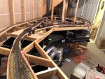
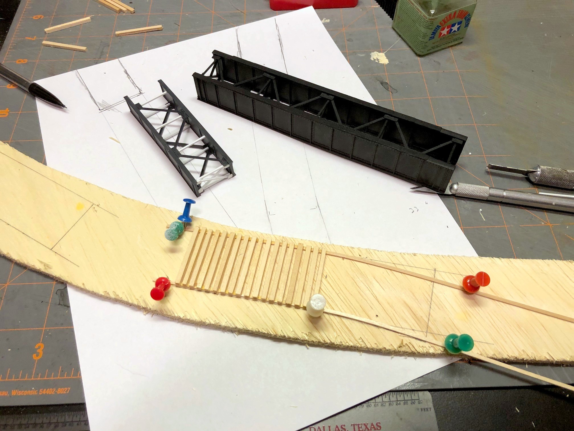
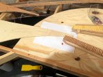
Laying bridge ties for the shorter bridge over Bailey’s Trace
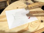
The toughest part of this scene is the pair of bridges across Bailey’s Trace at one end of the wye. On the prototype, there was a plate girder bridge just over 50′ in length on the main, and a shorter plate girder bridge (about 25′) which adjoins a curved bridge portion which appears to have been joined with a short wooden trestle on the curved portion (it’s all been redone with ballasted decks now). I used a 50′ Micro Engineering bridge for one section and cut down a 30′ ME bridge by one section on the other. I hand-laid the bridge ties using a template I drew up on a piece of paper. Next will come the concrete supports so I can attach the bridges and lay the rails across.
It’s encouraging to see progress in the layout room again, and I will definitely have my work cut out for me between now and Christmas hand-laying 14 switches!
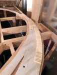
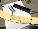
First ties laid for the St Charles scene, a 24″R and 30″R curved turnout
Overall view of the wye at St Charles including the house track and engine track inside the wye and the bridges over Bailey’s Trace
I drew in the bridge locations on a piece of paper
Drawing in the next subroadbed using the paper bridge template
Laying bridge ties for the shorter bridge over Bailey’s Trace
This is the future St Charles yard, just two long tracks on either side of the main
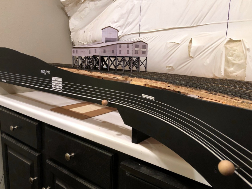
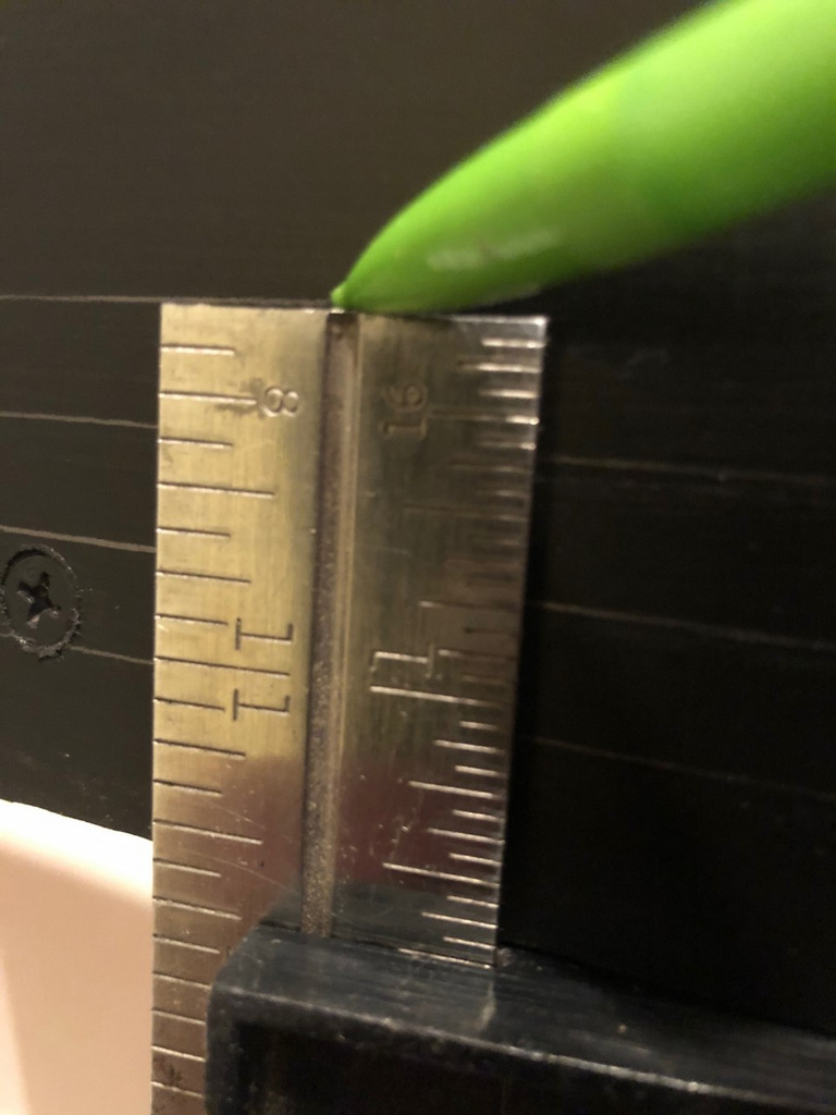
Finished fascia and labels at MayflowerI set a combination square to the right height and slide it along the bottom of the fascia while dragging a pencil across the top to draw straight lines for the track diagram
Working on the fascia is very mundane and unexciting, but as a human factors engineer by education, I take my fascia very seriously! On most layouts, the fascia is the primary interface between operators and the layout. It’s often where we place controls and place names, and it’s also a blank canvas we can use to help our operators better understand the scene they’re interacting with. Like many who perform switching operations on their layouts, I like to use the fascia to help operators understand as much as possible about towns, tracks and industries to aid in making their switching moves.
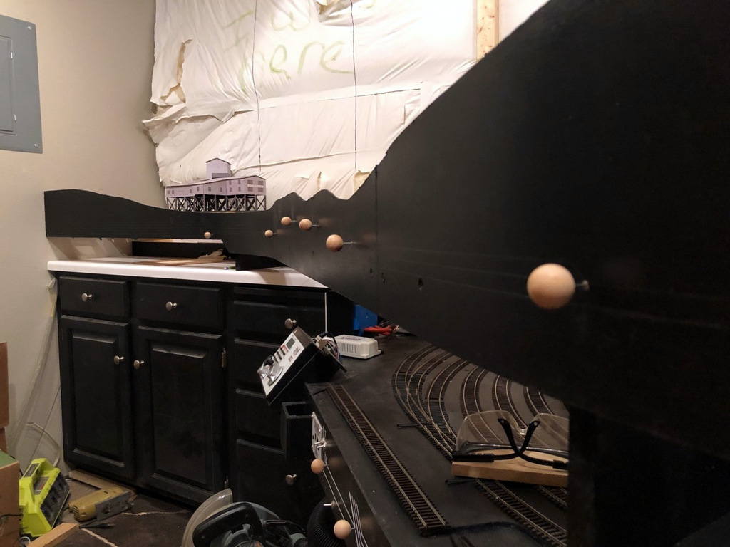
As far as construction goes, my fascia is just sheet Masonite fastened to the benchwork with drywall screws. I cut it in thick strips that will account for all the vertical scenery contours along the front edge. Where there are noticeable gaps or indentations from the screws, I touch things up with lightweight spackling compound and wipe it smooth with a damp cloth after letting it harden for about an hour–this saves a lot of time sanding later. Then I draw in the ground contour with a pencil and cut it with a jigsaw. A little black paint, and things are ready for the operator features.
All the Mayflower switch controls installed–they’re at different elevations to line up with the track diagram that will be installed on the fascia
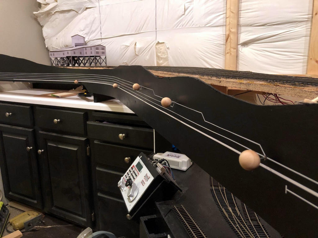
On my last layout, I drew the track diagram onto the front of the fascia, and it worked so well I decided to continue it on my new layout. It’s essentially an elongated track diagram like you’d find in a railroad track chart that lines up with the adjacent track and switches on the layout. I draw the lines parallel to the bottom of the fascia 3/8″ apart. To draw them, I’ll set a combination square so the end of the ruler is at the exact height I want when the square is pressed against the bottom of the fascia, then I’ll run the combination square around the bottom of the fascia while dragging a pencil along the top to draw it onto the fascia. I draw the switches onto the fascia at 45 degree angles with the convergence drawn where I want the switch control rod to be placed (directly perpendicular to the switch mechanism usually). One lesson learned from my last layout I was able to incorporate into this one is that the “straight” line through a switch control is the “normal” position of the switch while the “divergent” line represents the “thrown” position. It required a little “wiggling” of the track lines in the yard ladder to make this work, but it’s intended to help operators understand how to set the switches before departing a town.
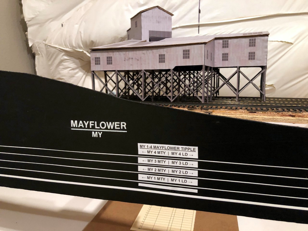
Finished fascia labels with the town name and siding identifiers for the Mayflower Tipple
I installed the switch control rods (see full article on switch control mechanisms here) after the lines were drawn but before placing the graphic tape on the fascia to represent the tracks. I use two sizes of white graphic tape for the tracks, 3/32″ to represent the main, and 1/32″ to represent sidings. This offers another visual clue for operators so they know which tracks not to block and what to leave clear after leaving town. Next come the labels. Every town on the layout has both a name and a unique 2-letter destination code for routing cars. In this case, Mayflower is represented by “MY.” Within each town, each track has a unique number, for example, MY 1 is the tipple track for the Mayflower Tipple closest to the main. For tipples, I also designate where the empty (MTY) and loaded (LD) cars go, so an empty hopper destined to be loaded on Mayflower’s outermost track would need to be placed at MY 4 MTY. Towns are labeled with large dry transfer lettering with the town name above a line and its destination code in smaller letters below. I also cut a small gap in each track tape on the fascia near the switch and use dry transfer numbers to label each track by number. Industries are given white labels with black lettering that gives the industry name, town initials, track number(s) and MTY | LD track dividing line if needed (see picture of the Mayflower Tipple and its labels). If two or more industries are on the same track, I use a “B,” “C” or so forth to denote each spotting location. In the case of Mayflower, I’ve identified a spot on load track 4 where I might have operators occasionally spot cars of supplies and a spot on the tail track of the main where I might have them spot covered hoppers of AN–each of these spots has its own industry label adjacent to the correct track on the fascia track diagram to make it clear where to spot the cars.
There’s nothing really novel here, but I do think this method of using track diagrams on the fascia and integrating switch controls, town names and industry track designators with unique operational codes goes a long way toward making the layout more intuitive and operator-friendly.
Roughed in masonite fascia awaiting sculpting
Here the fascia has been cut to shape, sanded, and painted
I set a combination square to the right height and slide it along the bottom of the fascia while dragging a pencil across the top to draw straight lines for the track diagram
All the Mayflower switch controls installed–they’re at different elevations to line up with the track diagram that will be installed on the fascia
Extra wood glued behind the fascia supports the switch throw rods and makes the fascia stronger
Nearly final fascia in Mayflower with the track diagram in place
Finished fascia and labels at Mayflower
Finished fascia labels with the town name and siding identifiers for the Mayflower Tipple
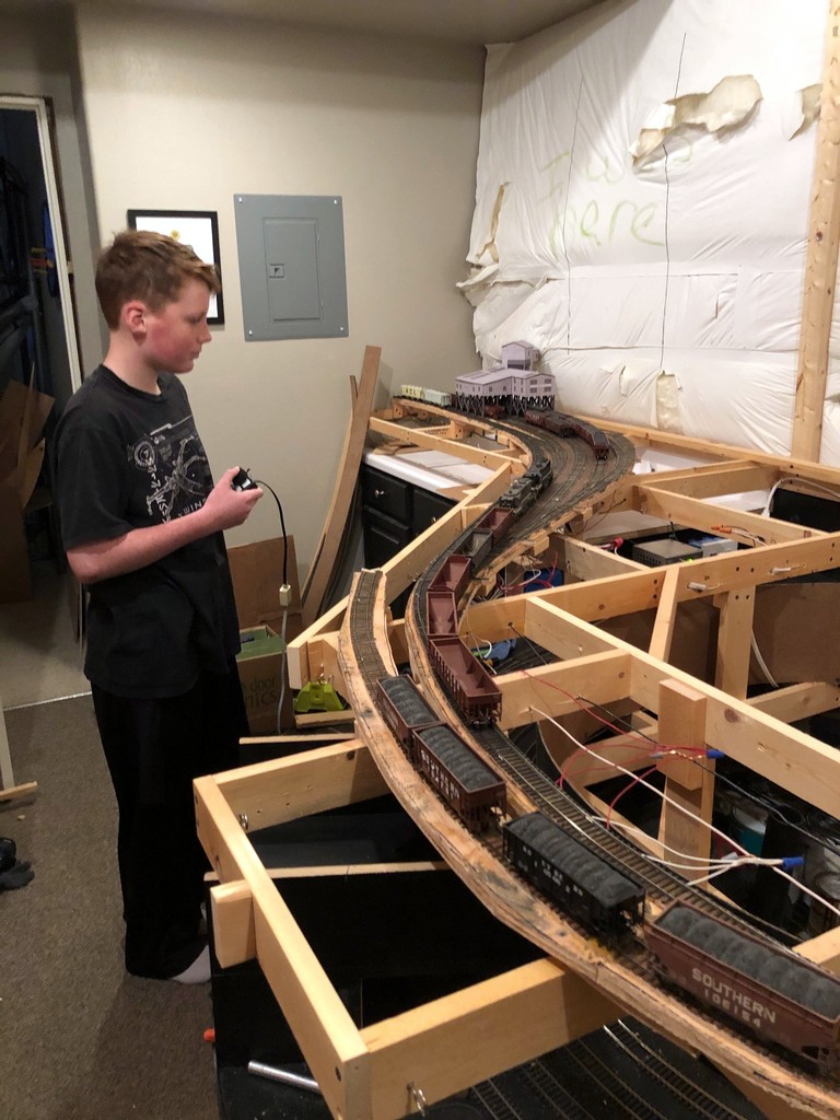
My son, Drew, was the engineer for the first mine run on the layout, a “Black Mountain Local” working Mayflower and Baker
Saturday was a big day–the first operational train worked the first loaders on the layout. It was a “Black Mountain Local” with me as conductor and my son, Drew, as engineer. Things overall went pretty smoothly with only a single derailment in the entire session (not bad for the first time operating on hand-laid track). Our power was GP38 2877 and GP30 2534. We picked up our train of 13 empty hoppers and a single loaded ACL covered hopper (AN for the mines). Awaiting us in Baker were 4 “yellow ball” loads for the transloader in Appalachia followed by 8 loads at Mayflower and an empty covered hopper.
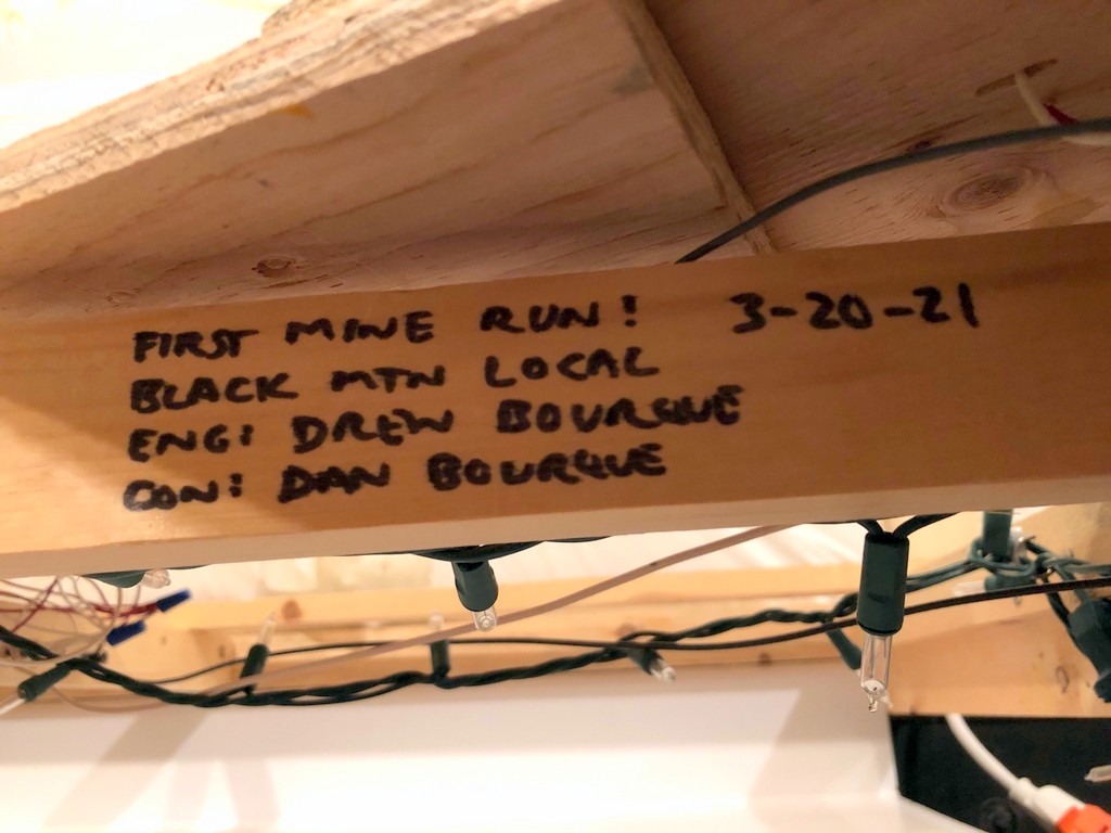
The tracks at both Baker and Mayflower are stub tracks (prototypical), so most of our time was spent pulling loads to clear tracks and running around empties 5-at-a-time in the single run-around track. It was a great time to teach my son about run-arounds, delayed couplers, and how to think through switching moves. Despite the lack of scenery or even operational throws for the switches (I had to reach under and throw the mechanisms directly), it was 30 minutes of pure joy more than 3 years in the making (since we moved in). We finished the shift with the entry of this “milestone” marker on the benchwork to commemorate the event.
“Milestone” entry for the first mine run worked on the layout
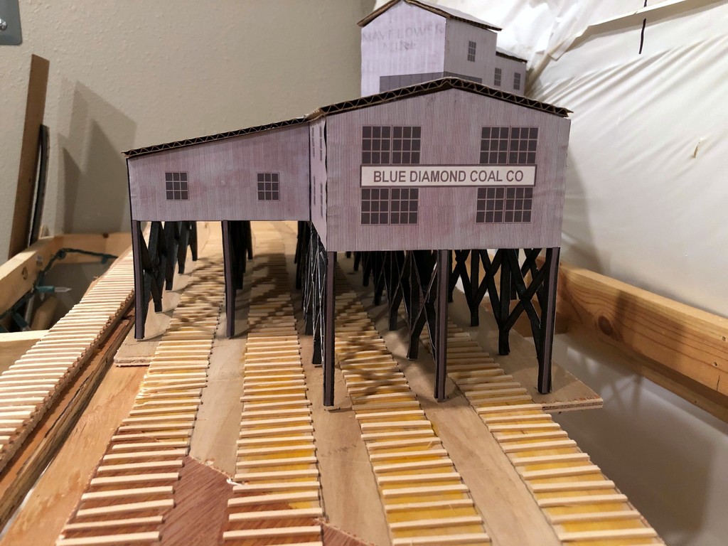
A close-up of the Mayflower Tipple mock-up with ties running underneath
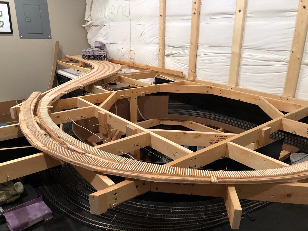
Made some progress this week on the Mayflower Branch section of the layout. All the ties have been laid! This is a tedious but simple process made a lot easier by the outline of track left over from tracing flextrack onto my subroadbed for cutting. I just place the material (1/4″ door skin for me) on top of the layout, place thumbtacks in the holes of a piece of limber Atlas flex track, fasten the track down with the pins using turn radius templates and “eyeballing” the rest, then use a pencil to trace down both sides of the track. For marking switches, I leave a portion of the track fastened and move the loose section to trace the divergent track. After tracing, where the pencil marks diverge is the location for the turnout points and longer block ties. After the subroadbed is secured in place with risers, screws and glue, I’ve got a perfect template for the tracks on the layout for laying ties (more about making and laying ties below).
Overview of the Mayflower Branch section of the layout with the ties freshly installed (this one’s for you, Bill)
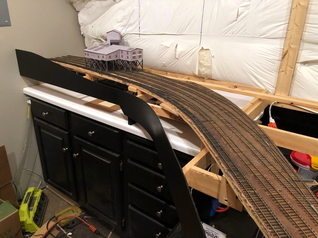
Now that all the ties are in place and I have the mock-up of the Mayflower Tipple, I can really start to visualize the entire scene. I’m really liking how the track snakes into the scene, and I think the gentle curve into the tipple will really look cool with strings of hoppers hanging out. You’ll also notice the tracks run into the wall–I didn’t have enough room to model the empty yard, just some space for empties above the tipple. This was an easy compromise to make for space because the empty yard at Mayflower was a stub-ended affair, so crews still had to run around and shove cuts of empty hoppers, just as they’ll need to do here. I can’t wait to get the rails down and operate that first mine run! There’s a lot of rail-laying between now and then, but it’s good to see it coming together.
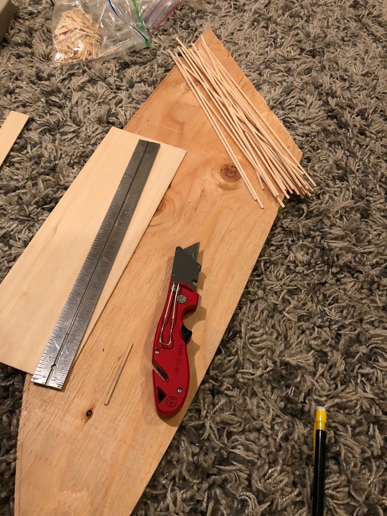
My “workbench” for making ties–I cut strips from 1/16 and 3/32″ basswood to use for siding and mainline ties, respectively.
Making Ties. Rather than buy bags of ties, I cut my own from sheets of basswood, 1/16″ for siding ties and 3/32″ for mainline ties. It’s not that ties on the prototype were different heights, but using different height ties on the layout keeps siding tracks a little lower than the main (very prototypical). I use a “spacer tie” to line up a metal straightedge the proper distance from the edge of the basswood board, then cut it with a couple strokes of a sharp utility blade. Most sheets come in 2′ length, and I’ve found it easier to cut it to 1′ length first so I don’t have to move the straightedge in the middle of a cut. With a bunch of sticks in hand, I then use a Northwest Shore Line “Chopper II” (amazing tool) and a scale rule to cut the ties in .5′ increments from a scale 8.5′ to 16.5′ with a separate, well-marked ziploc baggie for each size and length. Standard ties are 8.5′, and switches require a few of each longer size as you progress up the switch with 16′ ties for block ties at the points.
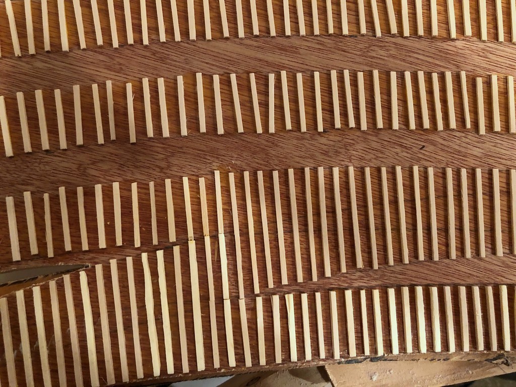
Ties tell a story about the type of track you’re modeling from mainline to well-used siding
Laying Ties. Laying ties is a simple matter of putting down some wood glue on the subroadbed and placing them. I work in sections of about 8-12″ at a time to make sure the glue doesn’t dry before the tie gets there. Ties tell a story about the kind of track you’re modeling, and it’s one of the reasons I love hand-laying track. Mainline track should be in good working order with closely spaced ties perpendicular to the rails and just a little side-to-side variation. Well kept sidings are similar but with perhaps a bit wider spacing between ties. For old, well-used sidings like you’d see at coal tipples, I’m pretty haphazard with my ties, allowing some of them to kink off perpendicular and lots of variation in spacing and alignment from side-to-side. It looks absolutely disgusting before the rails go on, but the effect is more subtle once the ties are stained and the rails are in place. I love disgusting looking track that still runs well, so I can be pretty aggressively messy when laying siding ties!
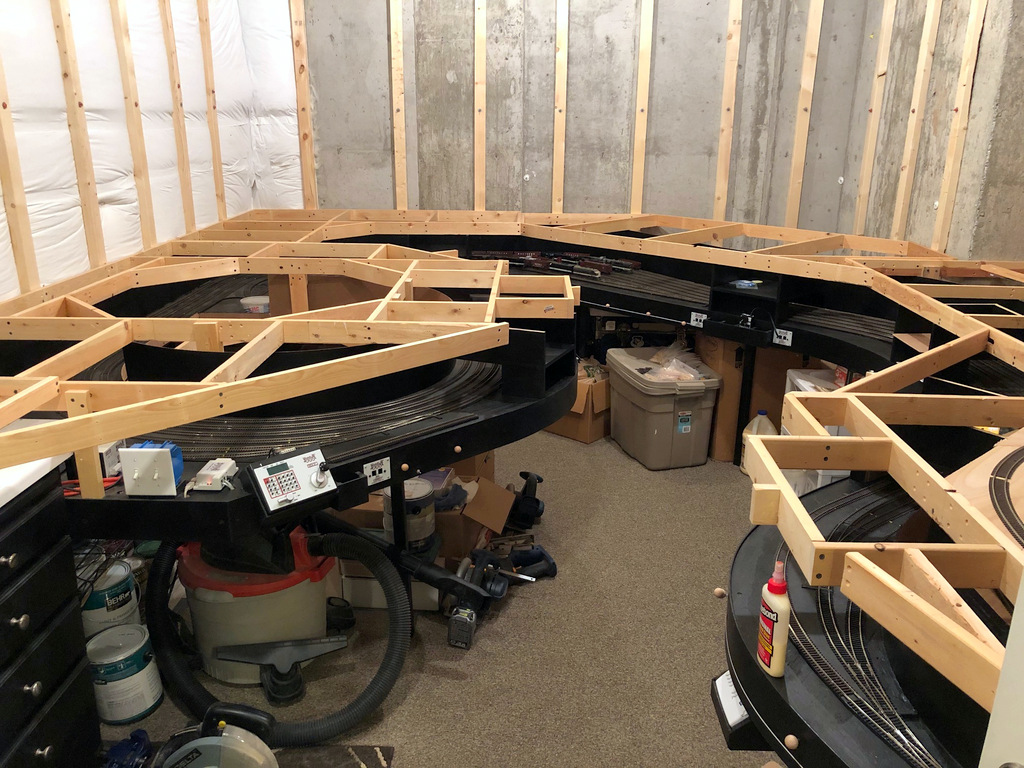
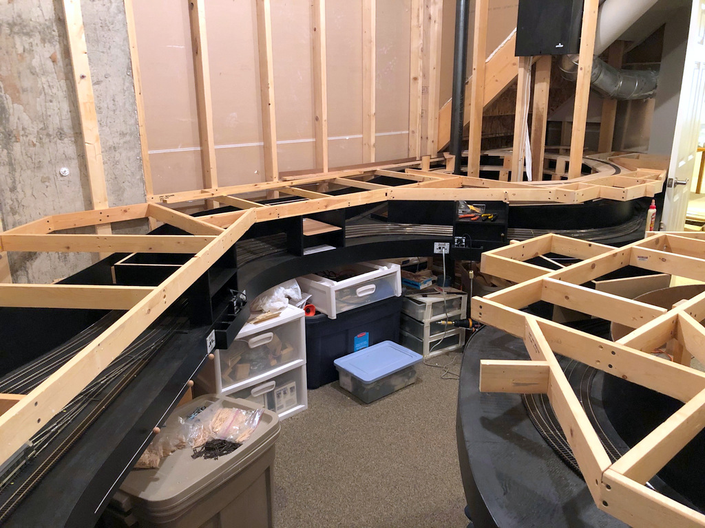
Finished lower level benchwork as seen from the door
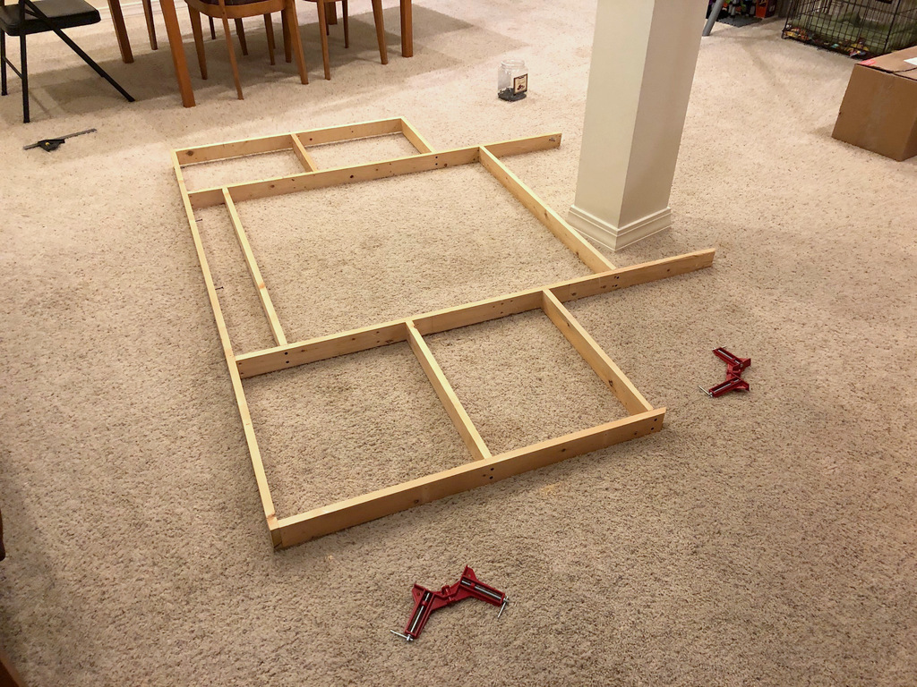
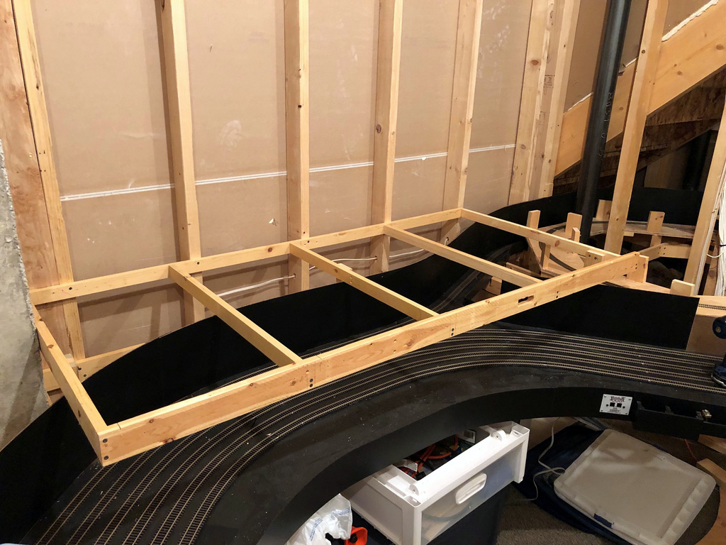
Well, the train garage now has a roof. Or in other words, I reached a major milestone today by completing the benchwork for the main level. What made this particular project tricky was I’m trying to match the fascia contours of the staging level exactly so they look like they’re one thick deck with staging under and trains over. The upper level won’t need to match, so parts of that project will be slightly easier.
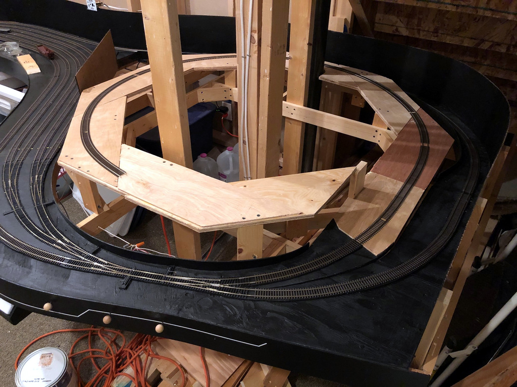
All the benchwork is open box, so most pieces were fairly easy to build. However, building the peninsula benchwork was tedious because 1) I needed a pretty big, single piece of benchwork to give it strength to reach from the wall to the edge of the peninsula, and 2) I needed a very specific octagon pattern at a very specific place in the middle of the peninsula to serve as the foundation for the second helix which will take trains from the lower (main) to the upper deck. I’m very glad I have an open basement area just outside the train room where I can build big pieces of benchwork. I’m also glad my wife announced she’d like to replace the carpet in the basement soon, so I’ll take advantage of this window for making messes on the carpet without repercussion!
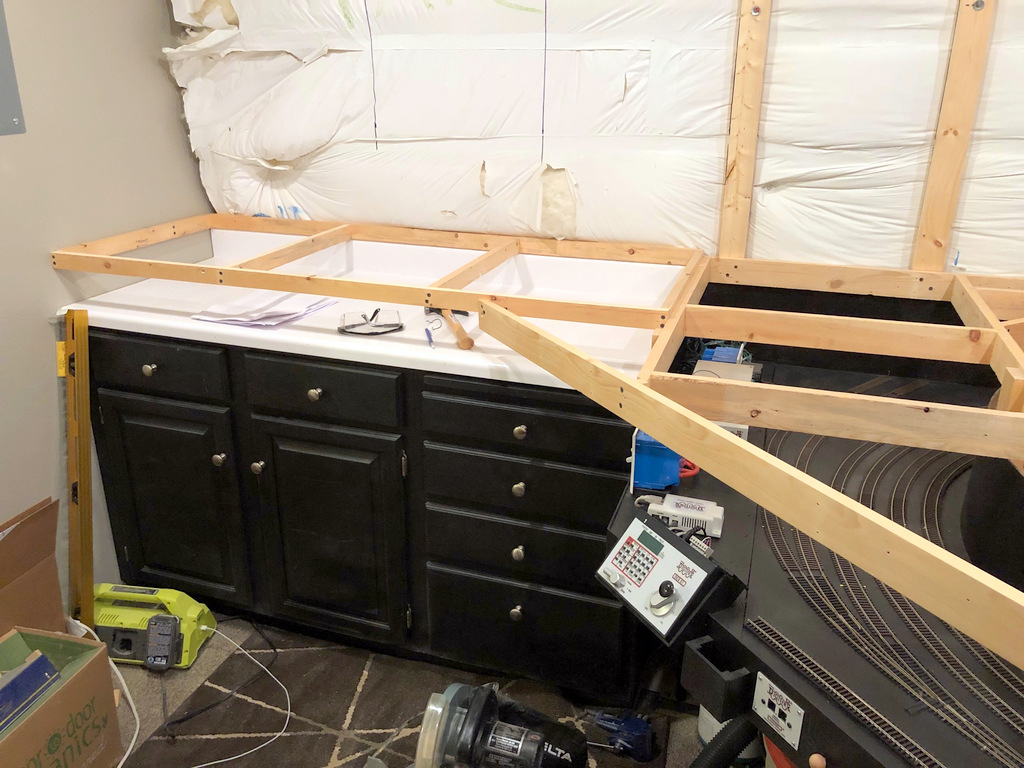
Benchwork for the Mayflower tipple in the corner–I really like how this space is turning out!
Now that I can really see it, I really like the space I’ve got between staging and the main deck. I could have brought the staging up a couple inches and still be ok, but it’s nice being able to see trains in staging just by backing up (instead of squatting down), and I like the functionality the fascia cubbies (now painted black) add – something not possible with less vertical space. I also like how the cabinet corner is turning out. I’ll still be able to reach all the drawers and the DCC components next to the cabinet easily, and it will make the corner under the Mayflower tipple look really finished when everything’s done.
Next step is to build the hidden connecting track between St. Charles and Mayflower (already started), and then comes the first subroadbed and track that will be part of the visible layout with scenery–exciting!
I’m grateful for an open basement room adjacent to the layout where I can assemble large pieces of benchwork like this piece of the peninsula
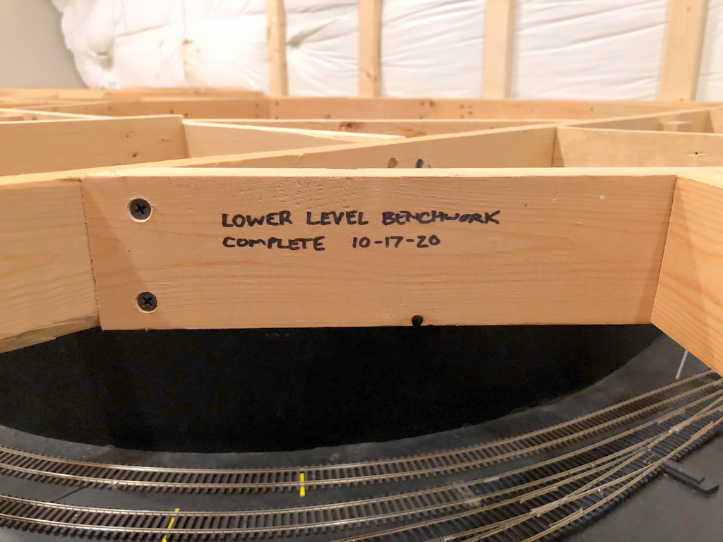
Here’s the milestone marking the occasion on the last piece of lower-level benchwork installed
Looking at the finished lower level benchwork from the end of the aisle
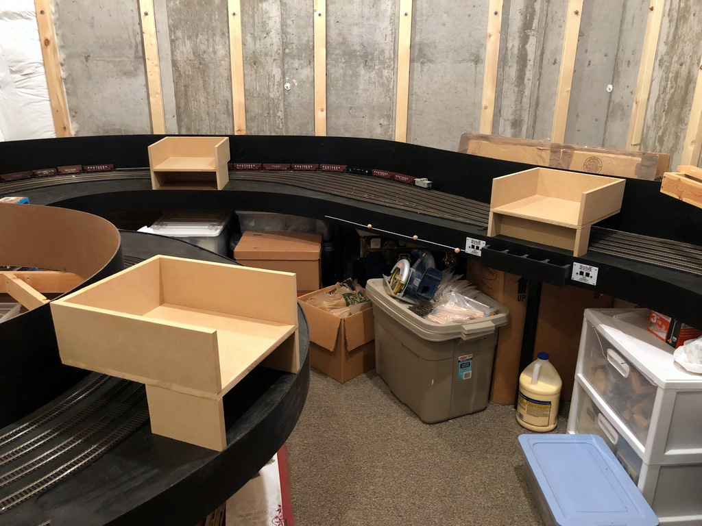
The final 3 fascia pockets are in place in preparation for benchwork being laid on top of them
I spent a few hours on the layout this past week primarily getting the staging level ready to have benchwork for the main level laid on top of it. There will only be 8″ or so between the decks, so it will be tough to do things like swing a hammer to nail down track once the main level goes in. I pounded the 100s of track nails down well to avoid trouble later, and I finished the final 3 fascia pockets for holding clipboards and other operator paperwork. As you can see, I tried to pick places where nothing is going on behind the pockets so I’m not covering switches or key viewpoints for spotting trains or clearing fouling points and the ends of tracks. Not sure exactly what I’ll keep in the lower pockets, though the one in the back corner is big enough to hold 8.5×11″ papers, so I finished it out with a masonite floor. I will say, I grossly underestimated the amount of sawdust MDF makes!
Using some extra space on the staging level for car storage tracks
While I was at it, I decided to fill up some of the extra space on the staging level with a few car storage tracks. Who doesn’t need more places to store cars, right? I’ve got plenty of staging, but being a coal railroad with little non-coal traffic, I wanted a place to store some of the extra non-coal cars that won’t be used every session, and I wanted to store them where I could easily add them to trains without taking up an actual staging track. I just nailed in 3 tracks directly onto the subroadbed in a spot that’s easily accessible and doesn’t block anything critical behind it like switches or fouling points for the active staging tracks. It’ll hold about 15-18 cars which will help. I’ve already got a coupe extra short staging tracks for the locomotives. These are connected to the railroad via a switch because I didn’t want to be picking up locomotives every time I swapped them out–I’m ok with the extra handling of freight cars.
While I’m giving an update, here’s a picture of the toughest benchwork on the layout so far–it’s the corner by the door that goes around the staging helix. What made it so tough is I wanted to match the curvature and location of the staging-level fascia below, and it happens to be a series of complex curves with NONE of the edge on a 90 or 45-degree line. I also wanted it to be secured well enough to walls, cantilevers and the helix that it wouldn’t need legs down to the staging level. I ended up building it in-place around the helix, and I’m satisfied it will do the trick.
Some of the toughest benchwork on the layout to match the curvature of the staging fascia and work around the helix
Just one more 1/2 turn to go before reaching the main level
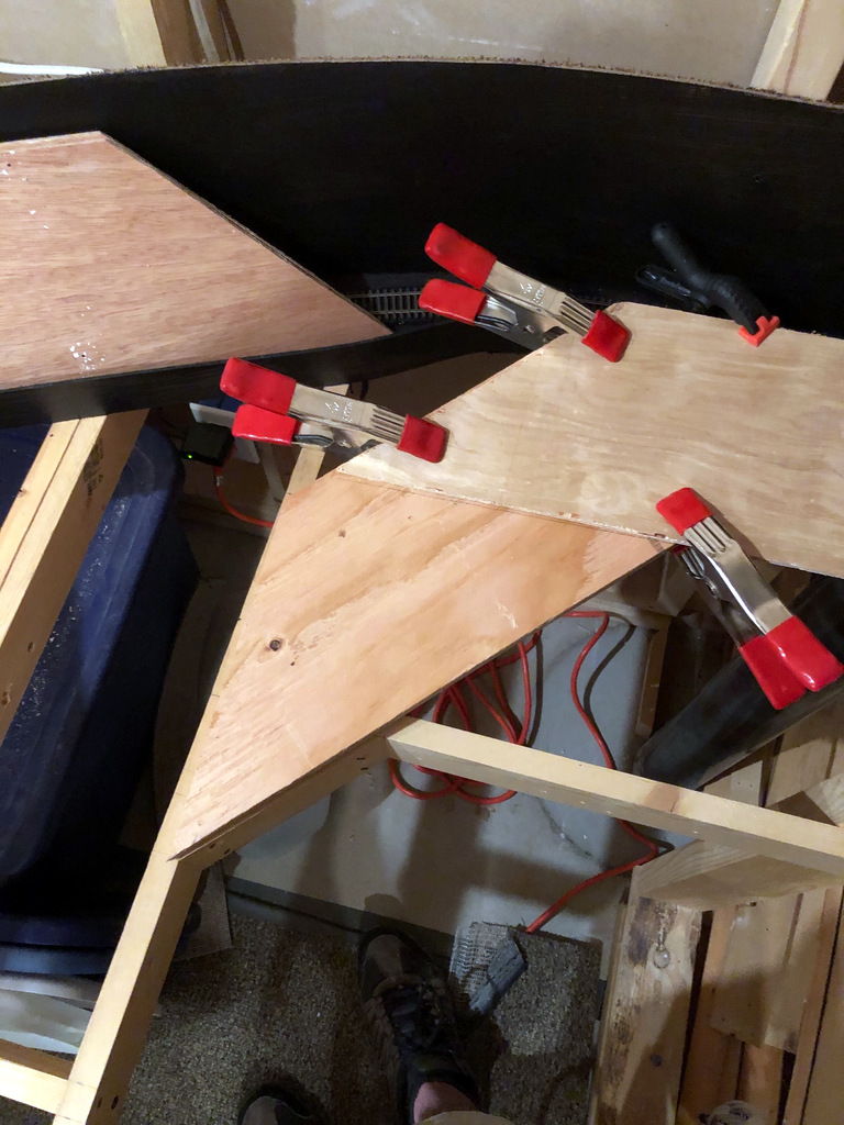
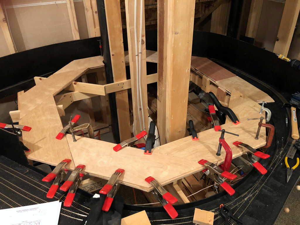
Just [almost] finished the first helix. Man, am I glad not to have to work around a floating wall for the second one! As promised, I’ve written an article on how to design and build a helix that’s strong, reliable, easy to build and an efficient use of space and material–it’s a design I call the “Double Pinwheel Helix.” I’ve built two helices this way now, and I haven’t seen another design that comes anywhere close to being this simple to build using nothing but plywood and a circular saw (no jigsawing for hours), and it’s very forgiving if you don’t cut the pieces exact or your space is a little wonky.
Rather than post it here, I put the article on Appalachian Railroad Modeling where more people would be able to find it and hopefully be inspired to overcome their fear of building a helix. You can find the article here. Here are a couple of photos so you can see the progress.
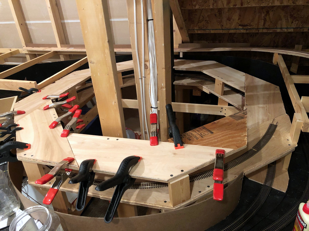
The key to the double pinwheel design is lots of clamps to ensure the lamination of pieces is thorough
A 68″ x 32″ piece of benchwork in and of itself is not terribly exciting, but to me, this piece is. It’s the first of many pieces for the main level, so it represents the first benchwork that will be covered in operational tracks and scenery. It’s the first piece that lets me feel the level of the trains during an operating session.
Here’s the first piece of benchwork for the main level
I had to pause on the helix project (you can see it half-built in the corner) because I ran out of plywood and had to wait a while to resupply. That got me thinking, though, that I need to put up a piece of benchwork so I can 1) see where the helix needs to connect, and 2) work the hidden track between St. Charles and Baker/Mayflower in before covering it with the helix. The hidden track will run right on top of this benchwork and under St. Charles; the St. Charles tracks will be about 2-3″ higher.
This piece of benchwork is a little strange in that it’s made of both 1×2″ and 1×3″ lumber. I needed the 1×2″ slimness to get the hidden track as low as possible, and I needed the 1×3″ on the fascia to give me plenty of room for switch controls and more support for leaning operators. It’s built to mirror the staging benchwork below it, so three risers in the middle of the crosspieces help make it sturdy.
I’ll admit progress has been painfully slow lately, but there is progress!
After a couple months of just breaking in the staging level and working out the bugs (and retiring from the Air Force, and going camping, and taking a trip to South Dakota…), I finally starting building again yesterday. I’ve got the first turn of the first helix that connects staging to the wye at St. Charles complete. 1.5 more turns to go.
First turn of the staging helix complete with track
This is the second time I’ve used this method to build a helix, and I really like it. I call it the “double pinwheel”–each level is essentially two layers of 8 identical trapezoids of plywood, each put together like a pinwheel with the two layers overlapping. It’s very easy (once you do the math to figure out your trapezoid and cut a master), it’s very forgiving, and it’s very strong after the glue dries.
Some particulars on the helix. It’s a 24″ radius helix that gains 4.5″ per turn. That works out to a 3% grade which should work fine for all the trains that will use it. The track you see looping around it (in the black painted area) is the continuous running loop connection. I was able to let a short string of cars run away from the top, and they negotiated the switches without a hitch at warp speed, even the #4 with REALLY short points going into the L&N staging yard you can see in the photo above (phew).
I’ll write a full article on the double pinwheel helix soon as I don’t know of anyone else who uses this method (let me know if you do). In the meantime, here are some progress pics.
Here’s a closeup of two pieces of the helix going together–I alternate top, bottom, top, bottom, gluing and clamping as I go
My limiting factor for how much of the helix I can build at once is clamps–it takes me about three sessions to build a level allowing about 90 minutes for glue to dry between sessions
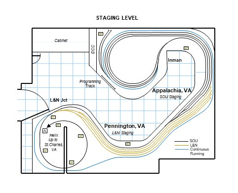
It occurs to me that I’ve been sharing all these pictures that show pieces and parts of the staging level, but I’ve never shared a drawing showing the staging plan.
Staging takes up almost the entire space below the lower level. The notable exception is a large cabinet in one corner that houses tools and supplies and a narrow space next to the cabinet dedicated to the DCC command station, booster, and computer connection. Adjacent to the DCC command station (currently a Digitrax Zephyr Xtra) is a 19″ section of track separate from the layout for programming locomotives. This area also houses two short connected tracks for storing locomotives not in use for a given ops session–I figured this was better than handling them all the time.
The rest of the level contains the two staging yards for the Southern and L&N, respectively. Southern staging, representing Appalachia, VA, consists of three staging tracks on a reversing loop with tracks of 21+ feet. Inman represents the upper end of Appalachia Yard (as it did in real life), and I’m using this moniker to differentiate the “business end” of Appalachia from the reversing loop connection end. A forth track snakes around the reversing loop to form a continuous running connection on the other end of the layout where the helix goes up to St. Charles. I plan to use this to break in new locomotives and to entertain kids–in a pinch it can be used as a fourth Southern staging track.
Tracks on the staging level are now complete. The last piece was the 4-track L&N staging yard shown here.
Under St. Charles is a 4-track, stub ended staging yard for the L&N which represents Pennington, VA where the short Pennington Branch left the L&N’s Cumberland Valley main to connect with the Southern at Pocket, VA (technically L&N Jct), not far from St. Charles. L&N tracks are 13 1/2 feet long, plenty long for the single locomotive and short string of cars that usually plied these rails. Four tracks is about three too many, but this will allow some “fiddle staging” for less commonly used cars (e.g., boxcars) and hoppers from other eras.
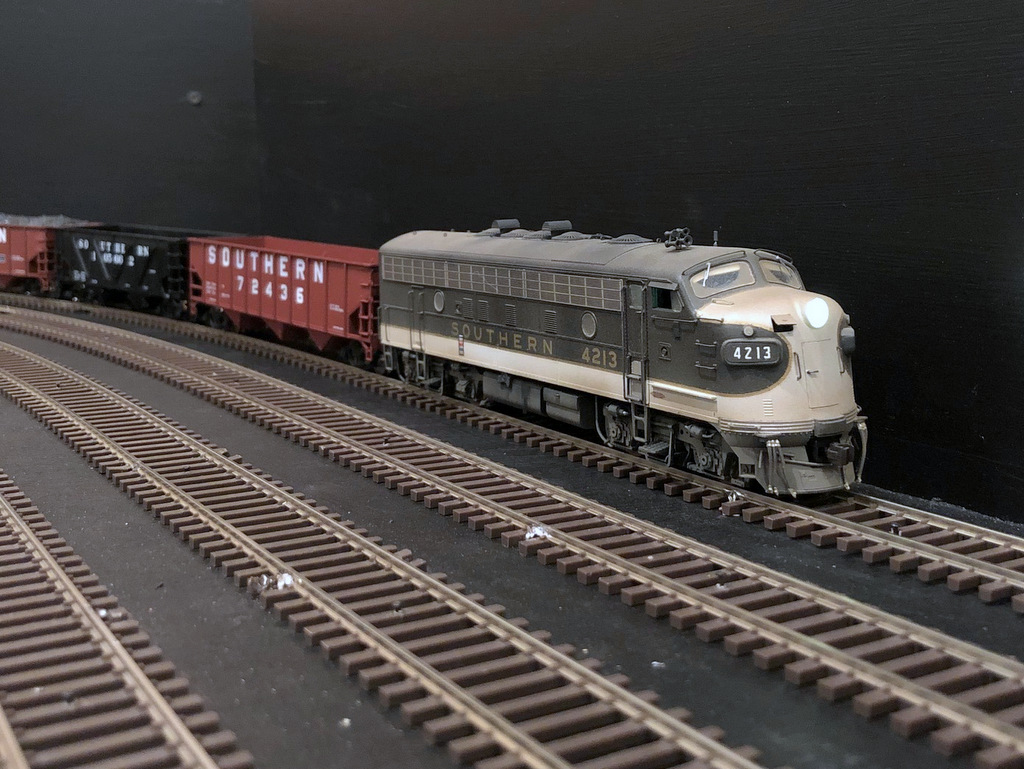
Yesterday, my “benchwork” became a “layout” with the running of the first locomotive. Of course, trusty F7A 4213 was the first locomotive, and my boys did rock-paper-scissors to determine who would be the first engineer. My oldest won, but all three of us got a chance to run around the half of the staging level with completed wiring.
This is the first train to run on the layout on April 17th 2020
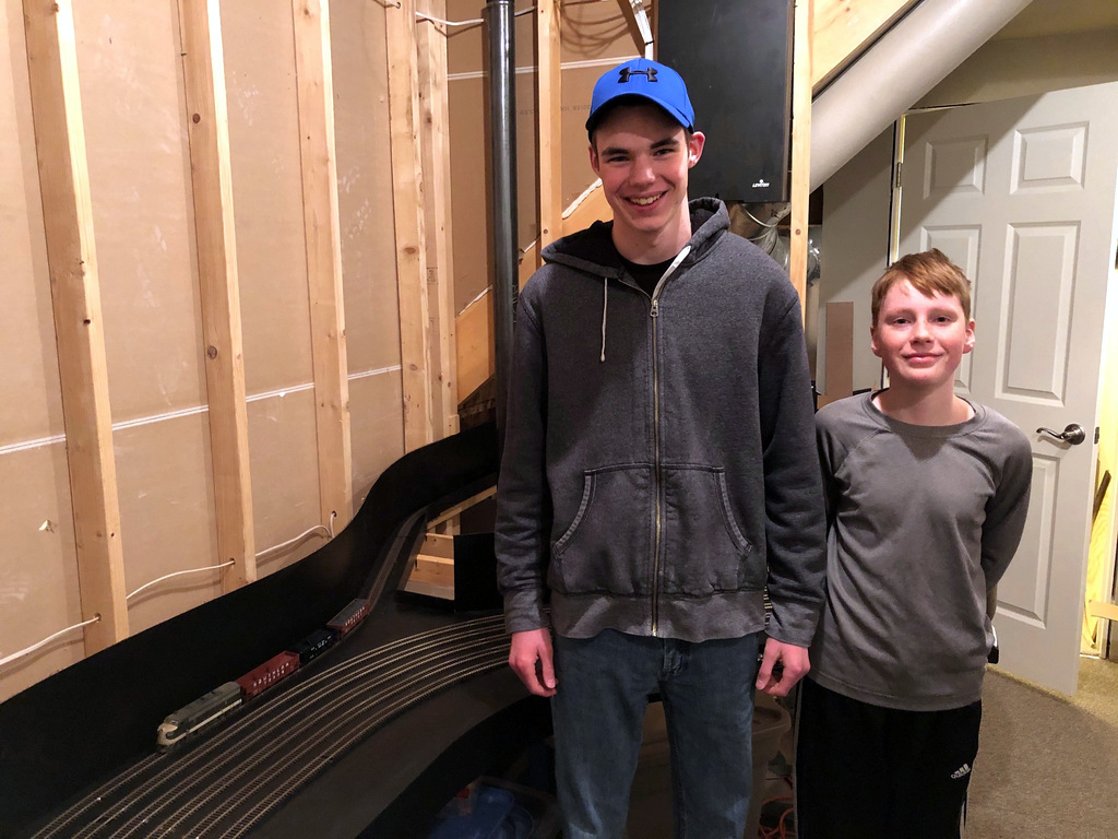
My two sons crewed the first train on the layout
Half a train, half a level, and no scenery in sight, but it was still a magical moment to see all that planning and work to this point pay off with a moving locomotive. As a bonus, the hand-laid switches performed well (despite not having their mechanisms in place yet), only a couple of protruding track nails on and excess solder in a couple joints (easily fixed) caused any issues.
I’m more motivated than ever to keep building!!!
My sons do rock-paper-scissors to determine who will be the first engineer
Last night, I put down the “bronze spike” commemorating the completion of track for the staging level. Not that exciting in the big scheme of things, but it is a major milestone in the layout’s progress!
Tracks on the staging level are now complete. The last piece was the 4-track L&N staging yard shown here.
The last piece of the staging level to be completed was the 4-track L&N staging yard representing Pennington, VA. This yard is stub-ended with tracks about 13.5 feet long. This is enough for a locomotive, cab, and about 20-28 hoppers. Based on photos, this will be more than adequate to represent the meager traffic the L&N hauled off the St. Charles Branch. I made it four tracks because I had the space, and this will give me some room to store trains and cars from “other eras” when not being used for a particular operating session.
There is still a bit more work to do before trains can run. I need to put in the switch control mechanisms and drop about 100 feeders to the main DCC track bus under the layout.
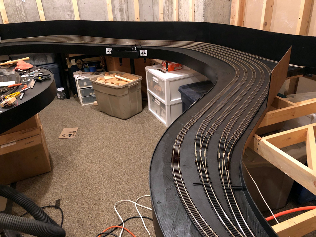
In the photo above, taken from the door to the layout room, you can see the Southern staging yard under the mess on the far left, the beginning of the Southern staging yard and end of the L&N stub tracks against the far wall, the Southern main linking staging to the helix (will occupy the open area on the right) along the right aisle, the L&N staging yard, and the continuous running connection entering along the right-hand wall–this last track connects to the Southern main via a switch just out of view in the lower right corner.
Another milestone today–the Southern Railway staging yard tracks are now complete! The yard, representing Appalachia, Virginia, consists of 8 hand-laid switches and about 40 pieces of flex track. The yard is three tracks on a reversing loop, one through track for mainline running (which can be used as a fourth staging track), and two short storage tracks for extra locomotives.
The Southern railway staging tracks representing Appalachia are now complete. The tracks form a reversing loop under the main helix.
The shortest staging track is about 21 feet long–that’s long enough for three locomotives, a cab, and 35-45 hoppers. . . should be plenty. A second, 4-track stub-ended staging yard with shorter tracks will help with L&N trains and holding excess cars.
Here’s one of the insulated joints going from the yard lead to a staging track on a reversing loop. I offset the joints about 1″ which is recommended for better performance of the auto-reverser.
I also fixed a problem with this website where the smaller images weren’t linked to their full-size cousins–that’s remedied now if you’d like to get a closer view of previous post pictures. Thanks to Stuart Thayer for pointing that out!