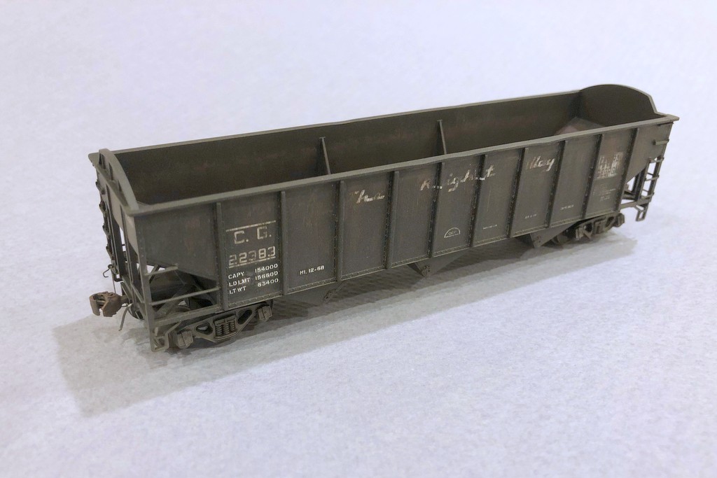
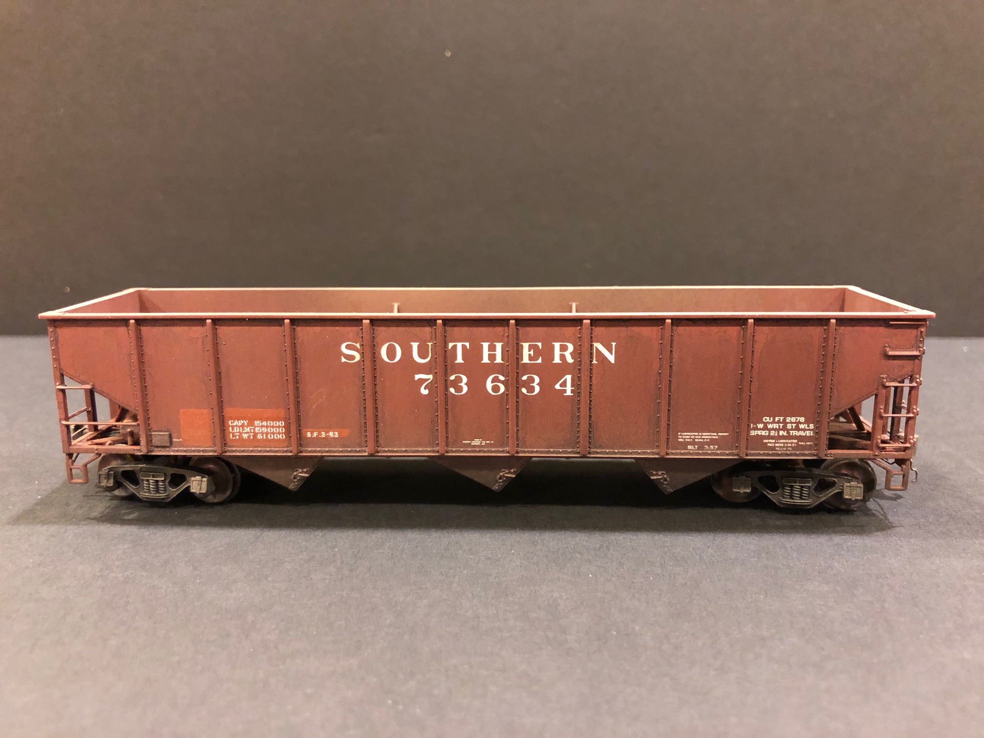
One of my goals is to have a fleet of “heritage fleet” hoppers representing each of the railroads purchased by the Southern and L&N in the 50s-70s. I’ve already got plenty of Interstate RR hoppers from the previous layout, but this is my first completed Central of Georgia hopper. Most of these were repainted into the Southern’s 74000 series, but some kept their CofGa reporting marks well beyond the merger. This model represents a car showing a lot of rust and wear and ready for the shop.
Old CG hopper ready for another trip to the shop for a repaint
It’s a stock, factory pained Atlas Trainman hopper with some detail upgrades including shaved-down grabs and a few wire details like the homemade trainline hoses and coupler cut bars. I spent most of the time on weathering. It’s mostly drybrushing to get the rust effects including the subtle ring inside the car. The data is supposed to represent a shop patch job, but it didn’t turn out as distinct as I would have liked. Lesson learned for next time.
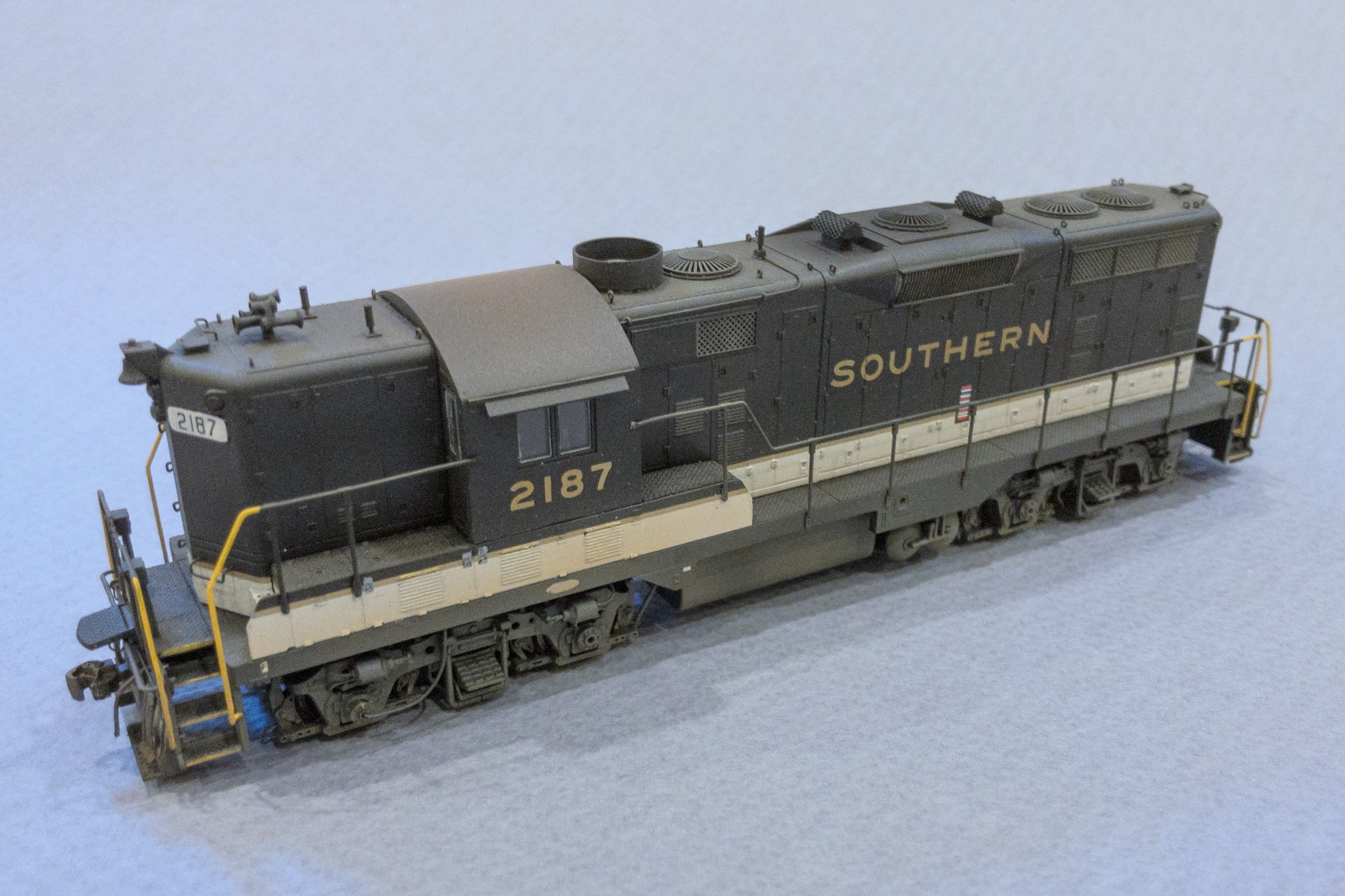
Today was a big day!… but it shouldn’t have been. It’s been an embarrassingly long time since I completed a locomotive model… like 7 years. Now it’s been less than a day as I put the finishing touches on Southern GP7 2187 today. This model started as a Proto 2000 GP7, and I’d gotten it through at least its initial detailing and coat of black paint several years ago. Last week, I finally decided it was time, and I decaled, added the last of the details, and weathered it.
Southern GP7 2187 from a modified Proto 2000 model
I modeled 2187 as she appeared around 1970. This was one of a handful of GP7s the Southern modified with Locotrol in the 1960s (hence the white number boards), but it seemed to spend most of its life in secondary service. Photos place it in southwestern Virginia in the late ’60s and again in ’71 after a trip to the shop that added the Southern-style sunshades and ACI tag. Modifications to the model include a 36″ dynamic fan, fan shroud and blank grill cover, scratchbuilt spark arrestors, modified fuel tank skirting, Southern-style sunshades, 5-chime horn, and Locotrol details like the 3 antennas and extra conduit.
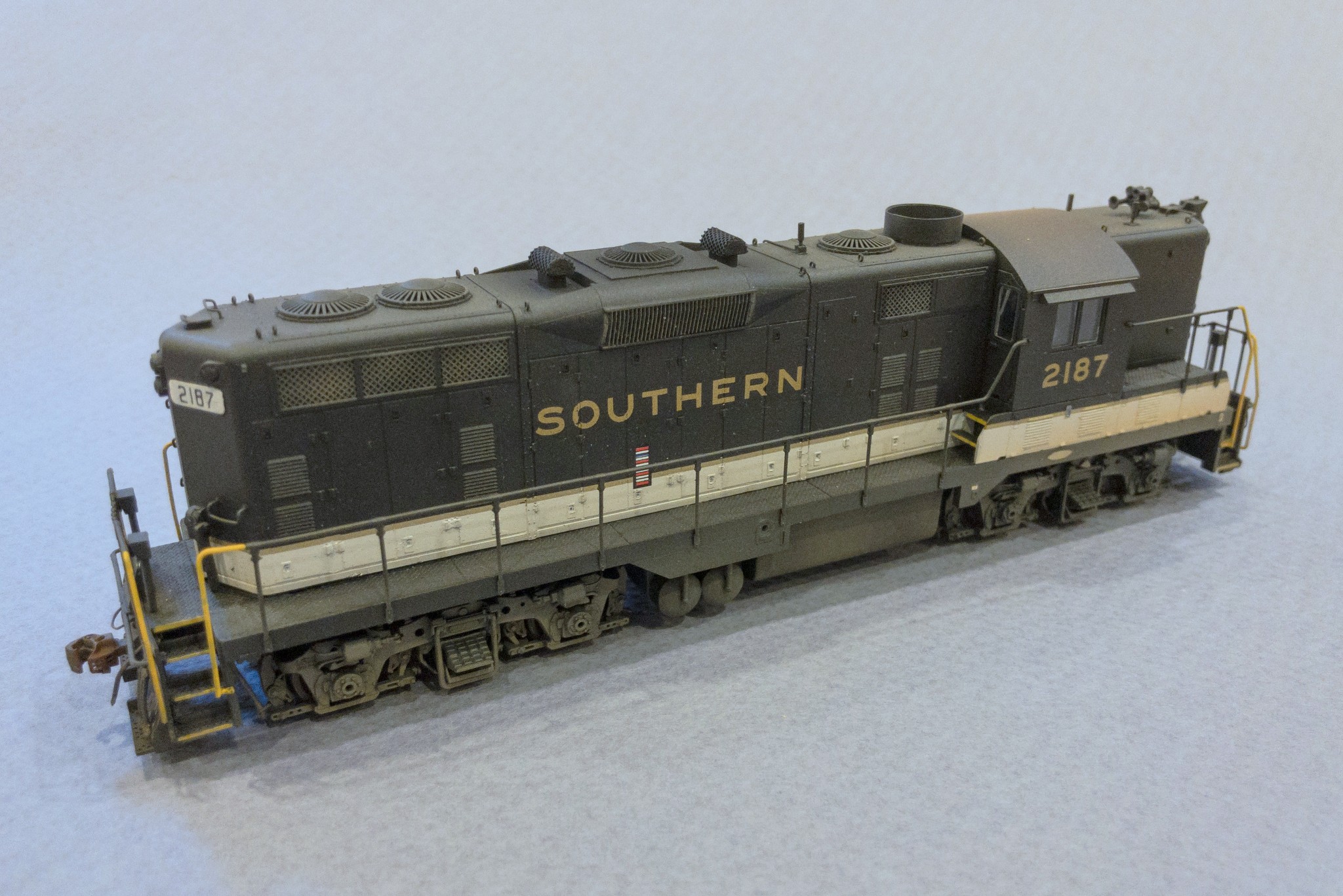
Southern GP7 2187 from a modified Proto 2000 model
Southern GP7 2187 from a modified Proto 2000 model
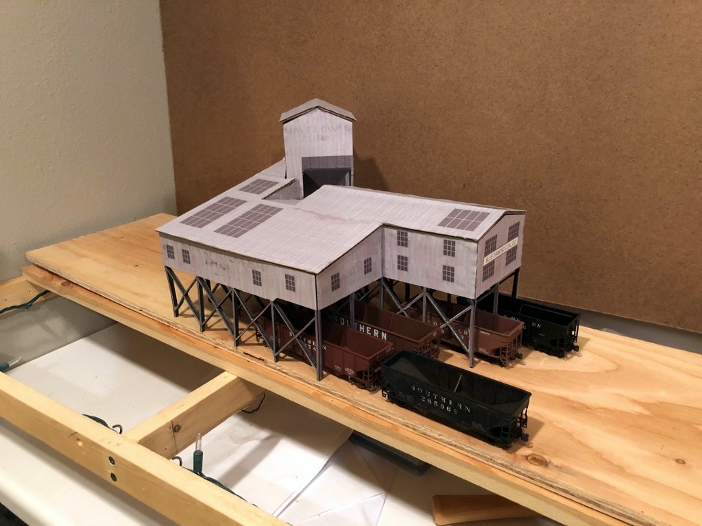
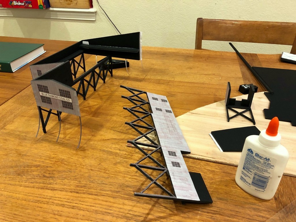
The final tipple mock-up in place on the layout showing its size relative to the benchwork and hoppers
I’ve finally started laying subroadbed onto the main level of the layout, and I’ve chosen the section between Baker and Mayflower as my first scene (see track plan). Mayflower is the first of four large tipples on the layout, so to make sure I’ve got proportions and track spacing right in the plan, I decided to build an HO scale mock-up from foam core and cardboard first. I’ll just warn you, this is not a time-saving process, but it certainly helps you visualize a scene and make adjustments before building more permanent structures and track. Because this was the first and the only large tipple on the lower deck where vertical spacing would be important, I decided it was worth the effort.
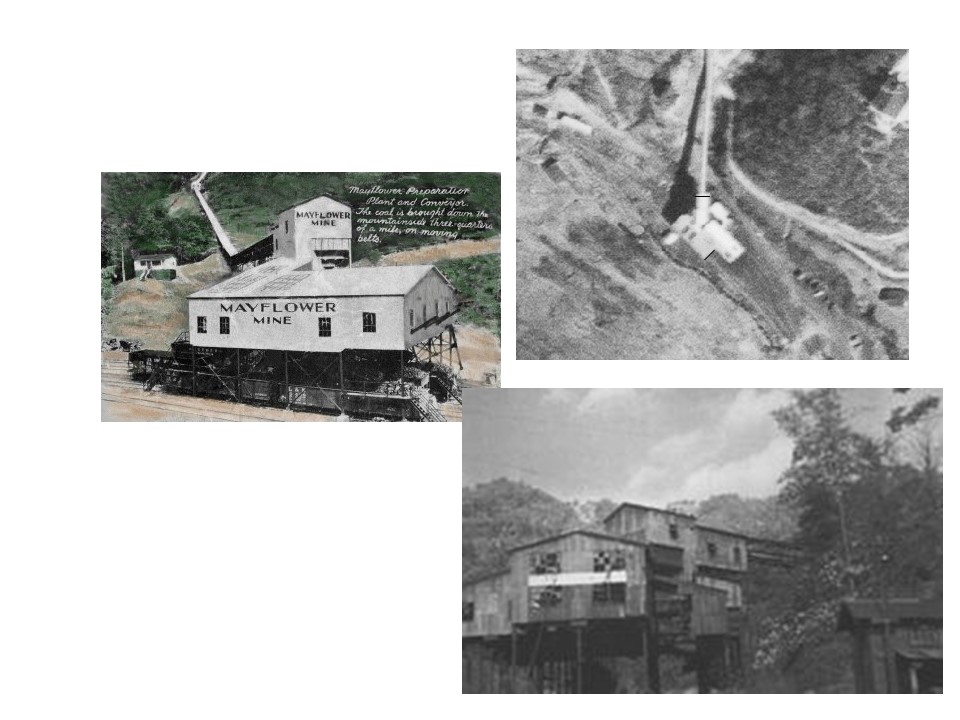
This is all of the photographic material I had from which to draw and build the Mayflower Tipple
Step 1 – Research. I’ve made a commitment to modeling the tipples as closely as possible (rule: no Walthers New River Mine allowed–it’s not a bad kit; it’s just over-used and too recognizable). The trouble is this area is not well documented by photos, so there’s a lot of guesswork and extrapolation involved. The first resource I had was a track chart that showed four tracks under the tipple, a medium-sized operation. Next, I found an aerial photo from the 1960s that showed the basic footprint of the tipple and the distinctive portion of the tipple connecting the tipple to the mine that sits 45 degrees to the tracks. Finally, I found a single grainy photo of the front of the tipple and a painting of it from a post card that someone had posted to Pinterest. With these resources, I had enough to rough-out a drawing.
Step 2 – “Scale” Drawing. Regardless of whether or not I’m building a mock-up or the final model, I need some sort of scale drawing to build from, and for tipples that were one-of-a-kind, actual drawings are very rare. I use the word “scale” here loosely because none of the research offered any clear dimensions. Still, distances between tracks and height above hoppers can be estimated, so I did my best. To make the drawing, I used my favorite drawing program, MS PowerPoint. No, PowerPoint isn’t designed for this, but it’s easy to use, and you can draw lines to specific dimensions and angles. I would work on one side, matching it as best I could to the photos. Then I’d copy relevant bits from the one side to use as size references for the next side until all the parts were drawn. Some sides were longer than a piece of paper, so I drew these as two separate drawings I could glue together later. The tricky part was the photo and postcard showed two different time periods for the tipple. The photo showed a section added to the front over two tracks, so I had to figure out how this might have worked in concert with the tipple represented in the postcard.
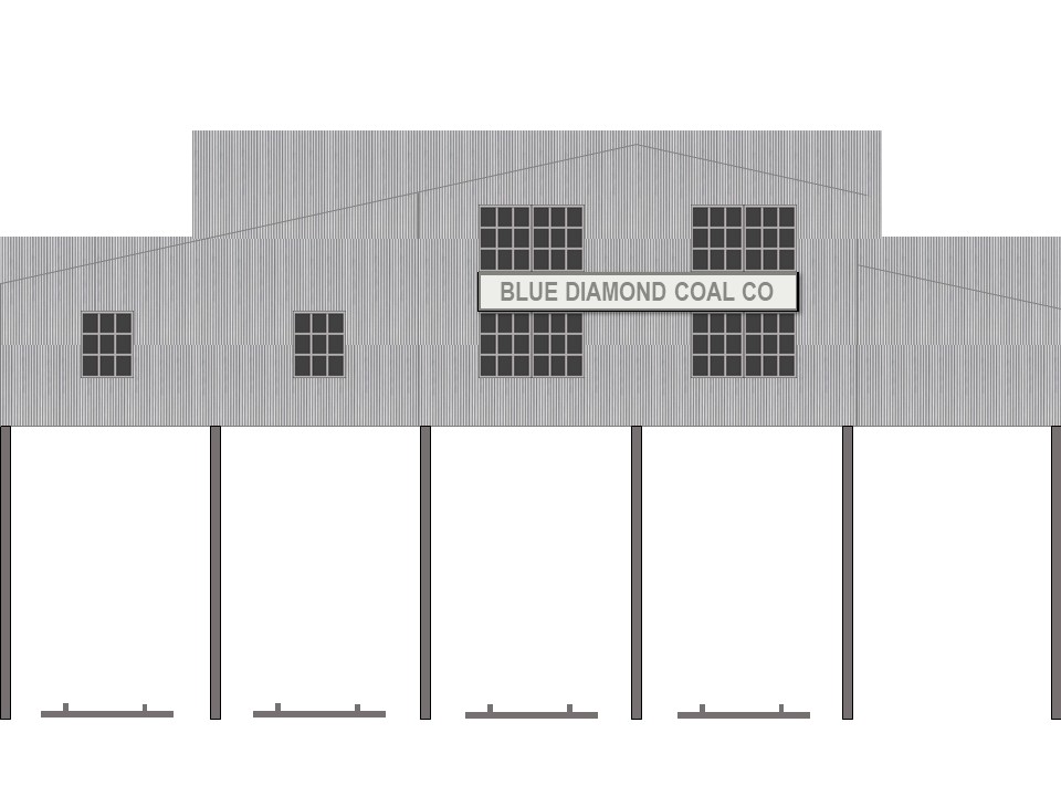
Line drawing of the front of the tipple showing the 2″ track spacing and profile
I decided to draw windows and corrugated metal siding on it as well. This was a simple matter of making a generic window and copy/paste it in place. The siding was just a texture I found online and copied into scale sheets to place behind the drawing (use the “send to back” function on right click). When everything looked decent, I printed it out.
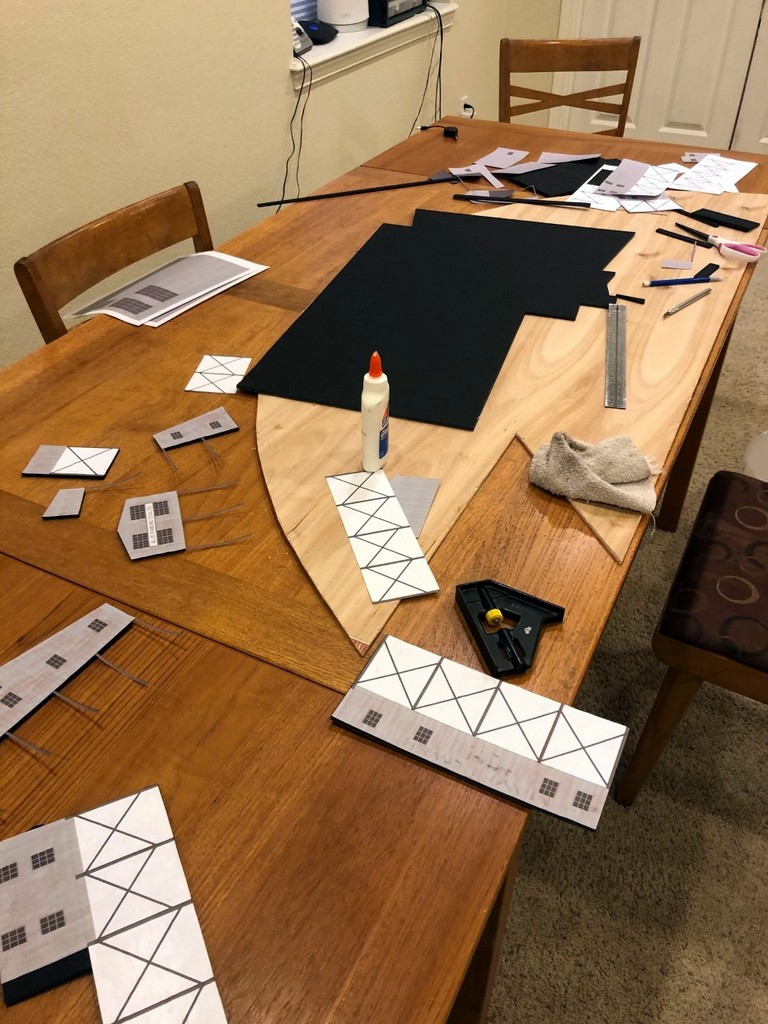
Step 3 – Building the Mock-Up. For material, I used black-on-black 1/4″ foam core picked up at the local big box hobby store. It’s easy to cut and work with and has enough rigidity to make a durable structure. I cut out pieces of the drawing and then glued them to the foam core using normal white glue. Where I have a corner, I needed to pick one wall to recess the width of the foam core so they won’t overlap (i.e., when gluing the drawing would overhang the foam core by one foam core width). As you can see from pictures, the glue caused a little discoloration and warping of the paper, but hey, it’s a mock-up. Next I cut along the edges using a metal ruler and X-Acto blade. The trickest part by far was cutting the intricate frames of the leg pieces (5 total). A mock-up doesn’t really require this level of detail, but I decided it was important enough to judging the look of the tipple that I spent an extra 3 hours or so cutting these out. The glue and paper caused some of the sides to bow a little, so for these I cut out 1/2″ wide strips of foam core to attach perpendicular along the back and bring them back into shape and provide lateral strength. This required laying a heavy book on top while it dried, but it worked well.
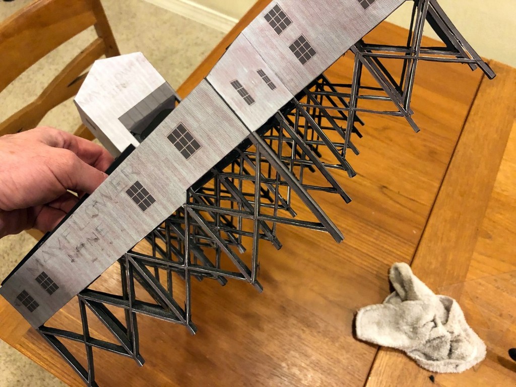
Tipple mock-up in progress–I worked one joint at a time
With the pieces cut out and strengthened, I started gluing them together. I worked on one corner at a time and used little pieces of square foam core to keep the corners square. I added structural pieces of foam core wherever needed to keep things sturdy. Again, the trick was to work one joint at a time (no more than two) instead of trying to build it all at once. The glue dried sufficiently in about 30 min, so I’d just come by every 30-60 min and glue another side on. Finally, I made the roof out of corrugated cardboard salvaged from a box–it’s a little thinner than the foam core but still has sufficient rigidity. After test fitting the roof pieces and making adjustments with the blade, I glued on the roof pieces–this is tricky because you have to worry about a lot of edges at once.
Step 4 – Evaluating the Scene. With the Mayflower Tipple mock-up complete, I could now mock-up the scene on the layout and see where the tracks would go, how tight the spacing would be for hoppers (adequate), how far I could bring it out or push it back in the scene, how much space I would have with the upper deck, etc. As it turns out, the tipple fits perfectly and doesn’t need any adjustment, but it would be easy to make cuts and repairs to the mock-up to try different things that would be a lot tougher to do on a final model. Any changes would simply be added to the drawing to use for the final model.
Conclusion. While I could have been halfway done with a permanent model in the time I built this mock-up, I now have the confidence in my drawing and in the scene to build the final model. Besides, it will be a while before construction on the upper deck in this area will be complete enough to install a permanent model, so in the meantime, the mock-up will give me and other crew members a good stand-in to enhance operations that I don’t mind getting a little roughed up. Beats having to use your imagination when switching out empty and loaded hoppers!
This is all of the photographic material I had from which to draw and build the Mayflower Tipple
Line drawing of the front of the tipple showing the 2″ track spacing and profile
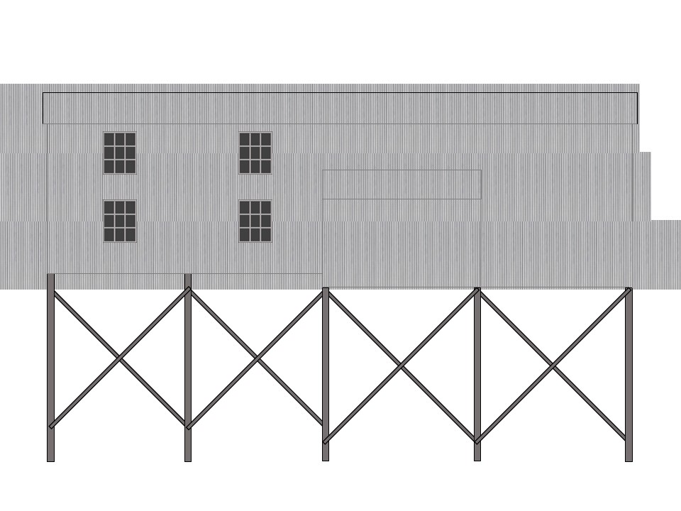
Example of a portion of the tipple drawing from the side showing the bracing
View of my messy workspace for building the mock-up showing foam core, cutting board, tools, and some finished pieces
Tipple mock-up in progress–I worked one joint at a time
Cutting around the leg pieces was by far the most difficult part of building this mock-up
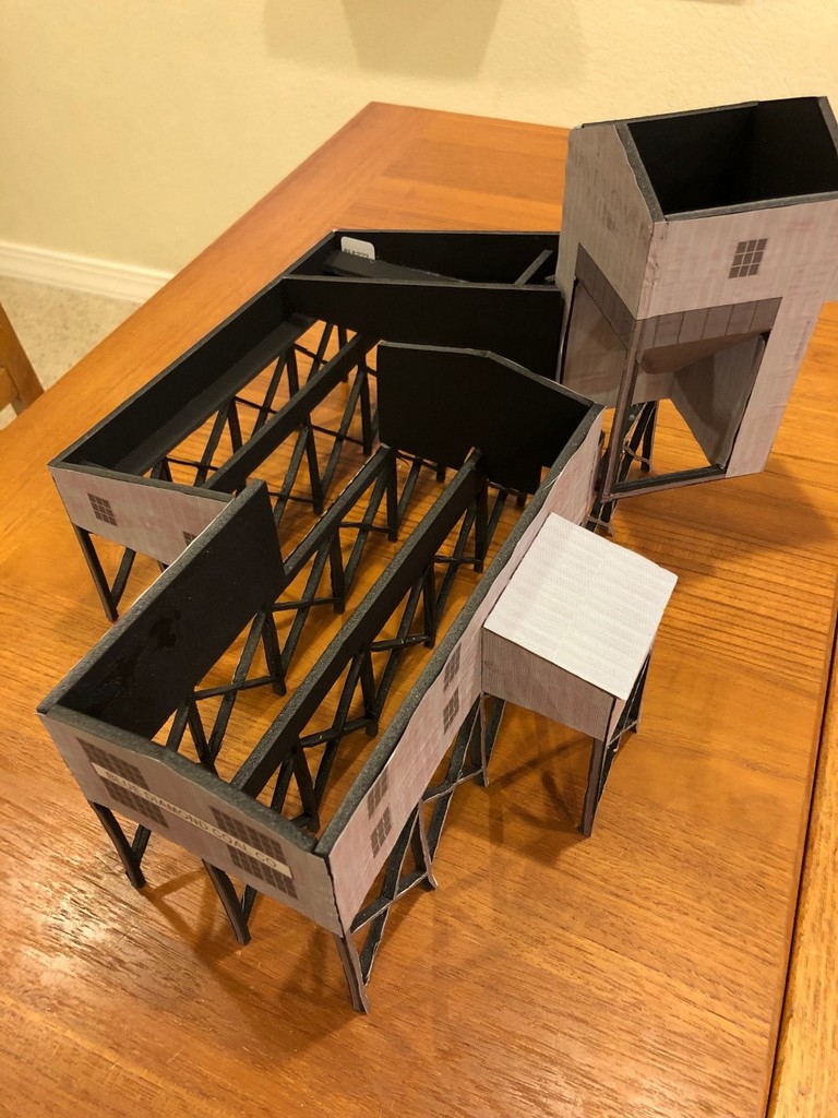
Good look at the final model before the final step of adding the roof–it’s pretty simple with just enough pieces inside to make it structurally sound
The final tipple mock-up in place on the layout showing its size relative to the benchwork and hoppers
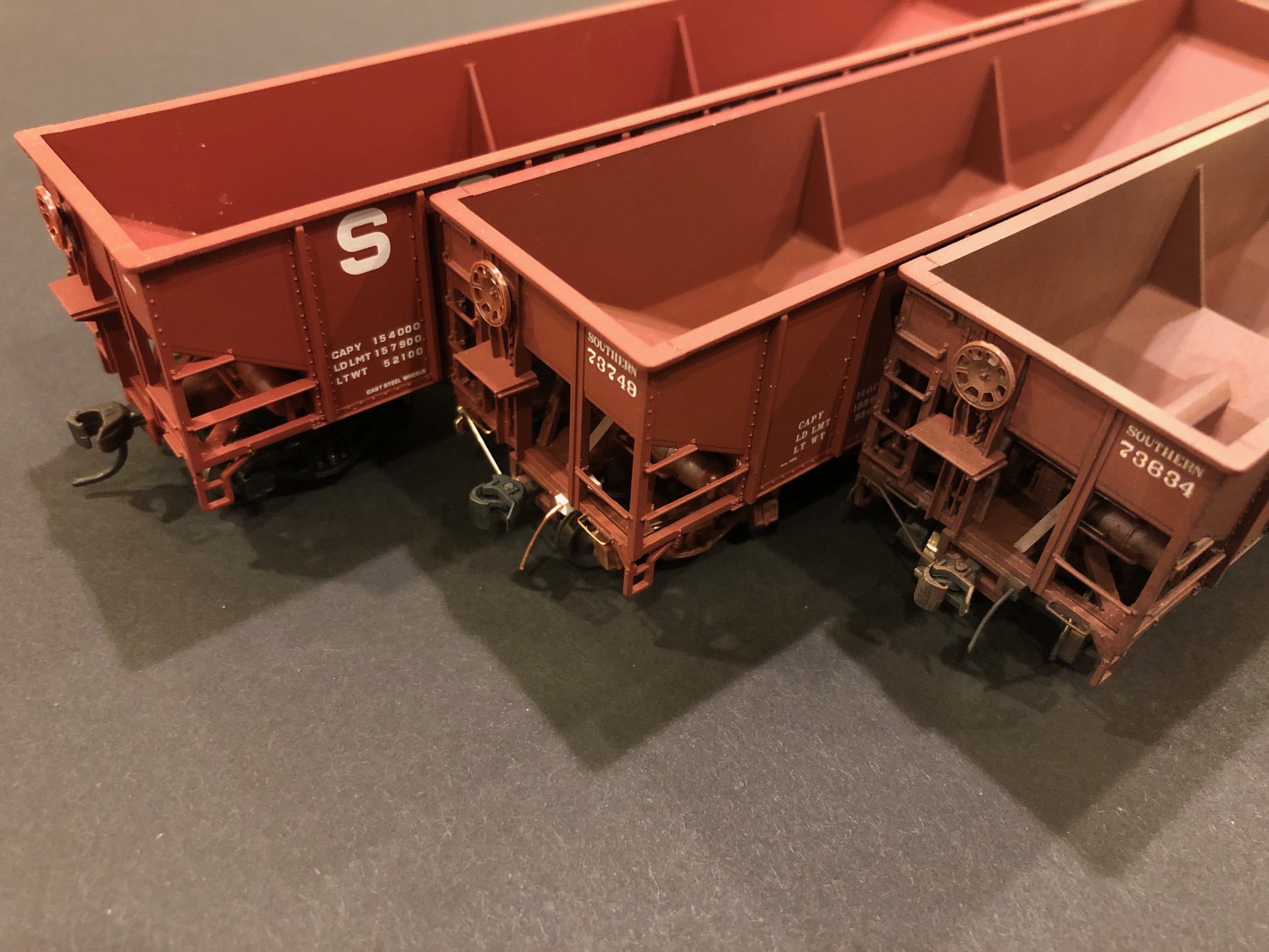
Atlas 70T hopper upgraded to the layout “standard” which includes factory paint, modified grabs, a few details, and multiple layers of simple weathering
In addition to building the layout, I’m also spending some time building the hopper fleet to occupy it. I figure I’ll need somewhere between 100-200 hoppers. I’ve already modeled more than a dozen classes of hoppers for the layout, but the most numerous hopper will be a Southern 70-ton 3-bay hopper. The Southern had about 4,000 of these cars in the 1960s, and thankfully the Atlas Trainman 70T hopper is a pretty close stand-in.
The detail on the Atlas car is slightly above what you’d expect from an entry-level model with sharp paint, good rivets and crisp detail, but it still needs a little work to be ready for a prototype-based layout. Out of the box, the most detrimental feature is the chunky molded-on grab irons for the corner ladders. I’ve superdetailed a few of these cars by completely stripping the ladders and adding individual wire grabs, but it’s a lot of work for a middle-of-the-train car–not something I want to replicate on 60 cars. I’ve found I can improve the look of the ladders significantly by carving away the thickness of the molded grabs with an XActo knife, and it takes a lot less time and detail parts than adding wire.
Comparison of three Atlas hoppers including one straight out of the box (left), one with detail enhancements in progress (middle), and a finished car.
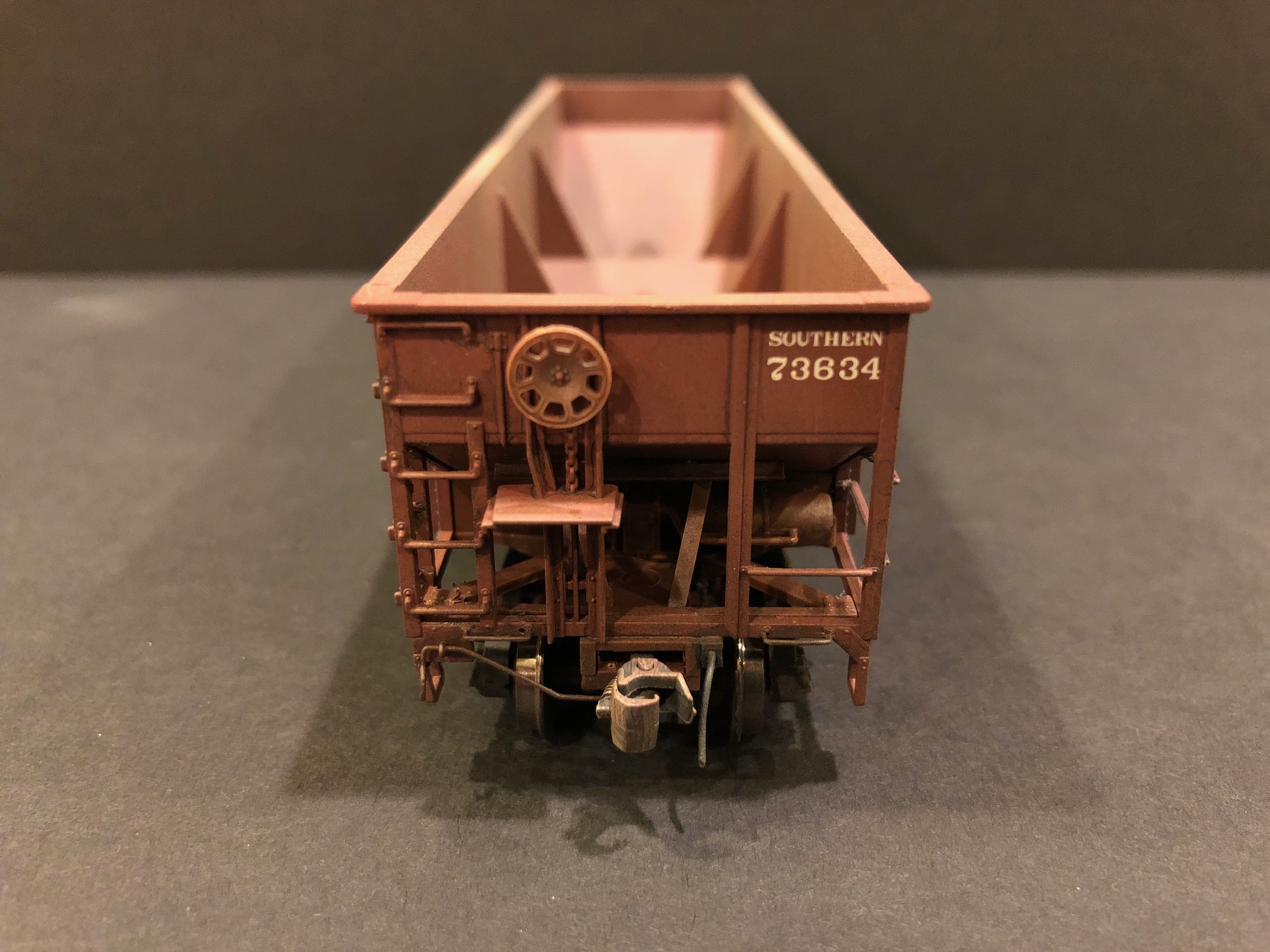
Additional details include a set of wire grabs on the end sills, a coupler cut bar, tack boards (scrap styrene), and a train-line hose made from a piece of stripped copper Cat 5 wire super-glued between two L-shaped pieces made into a box. While the wire lacks the detail of a molded plastic or brass part, it’s cheap, easy to make, and most importantly, it’s nearly indestructible (my last layout was littered with broken-off hoses). I also replace the plastic couplers with good-old Kadee No 5s. This was another lesson learned from the previous layout–smaller couplers like No 58s didn’t couple well on curves, and there are a LOT of curves on an Appalachian layout! The reliable operation is well worth the sacrifice in fine detail, though I’ll still likely keep the smaller couplers on locomotives and cabooses.
The final detail is the weathering which includes washes of black and grimy tan and light sprays of tan, black and rust via an airbrush. For some cars, I’ll also do some “restenciling” of the car data by painting fresh boxcar red over top of the washes and adding some decals.
Most of the detail enhancements are given to the ends of the cars
Being set in the 1960s and 70s, I’ll also need a few different paint jobs on the layout. Some will be the original black with Roman “SOUTHERN” lettering that most of the cars were delivered in. Several will be in the middle scheme with the older Roman “SOUTHERN” lettering on red. Most will be red repaints with the Most will be red repaints with the big rounded “SOUTHERN” lettering on the sides. For the Atlas cars, the repaint scheme often involves replacing the circular “O” with a more square “O” (the circles weren’t common until the late ’70s/early ’80s), removing the lube plates, and modifying the numbers to make them unique. I can usually remove letters, numbers and lube plates by repeatedly scraping a square XActo blade along the sides of the car. This mix of paint schemes and differences in weathering should add a good bit of realism to a train snaking through the layout.