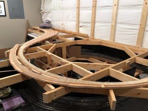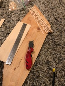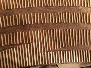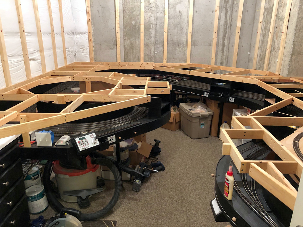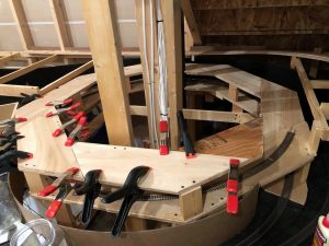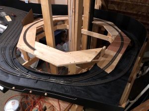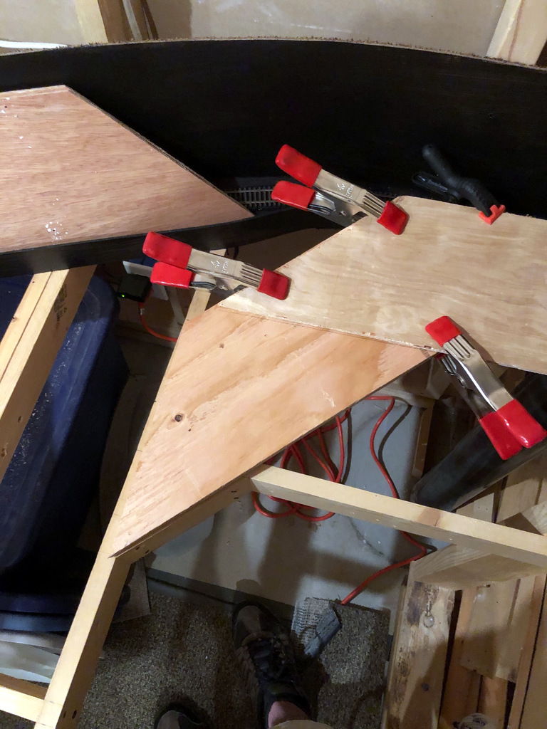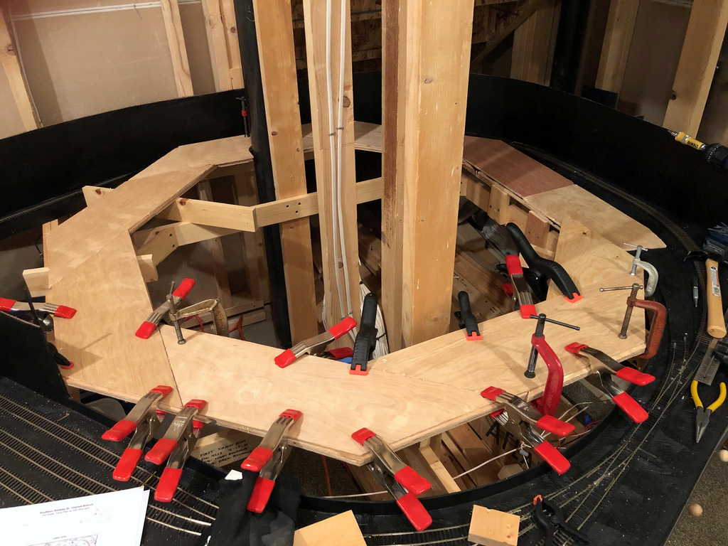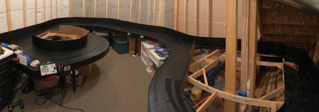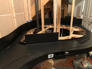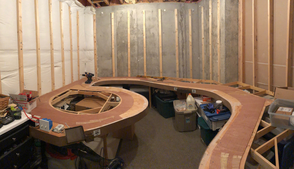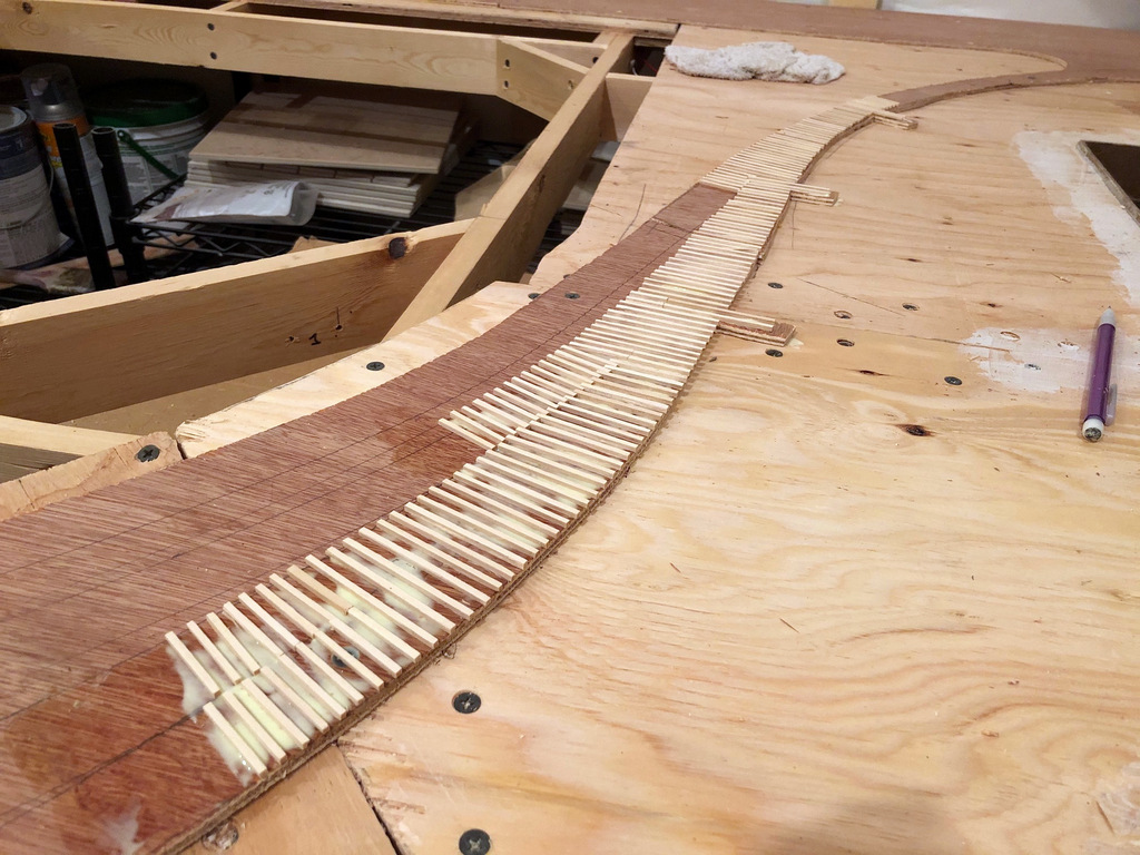
Just [almost] finished the first helix. Man, am I glad not to have to work around a floating wall for the second one! As promised, I’ve written an article on how to design and build a helix that’s strong, reliable, easy to build and an efficient use of space and material–it’s a design I call the “Double Pinwheel Helix.” I’ve built two helices this way now, and I haven’t seen another design that comes anywhere close to being this simple to build using nothing but plywood and a circular saw (no jigsawing for hours), and it’s very forgiving if you don’t cut the pieces exact or your space is a little wonky.
Rather than post it here, I put the article on Appalachian Railroad Modeling where more people would be able to find it and hopefully be inspired to overcome their fear of building a helix. You can find the article here. Here are a couple of photos so you can see the progress.
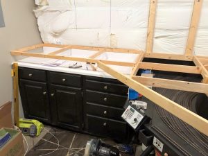
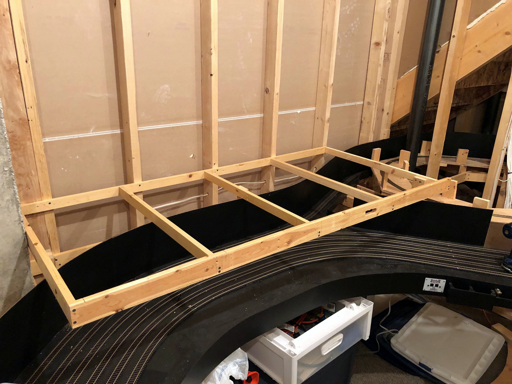
A 68″ x 32″ piece of benchwork in and of itself is not terribly exciting, but to me, this piece is. It’s the first of many pieces for the main level, so it represents the first benchwork that will be covered in operational tracks and scenery. It’s the first piece that lets me feel the level of the trains during an operating session.
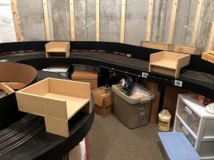
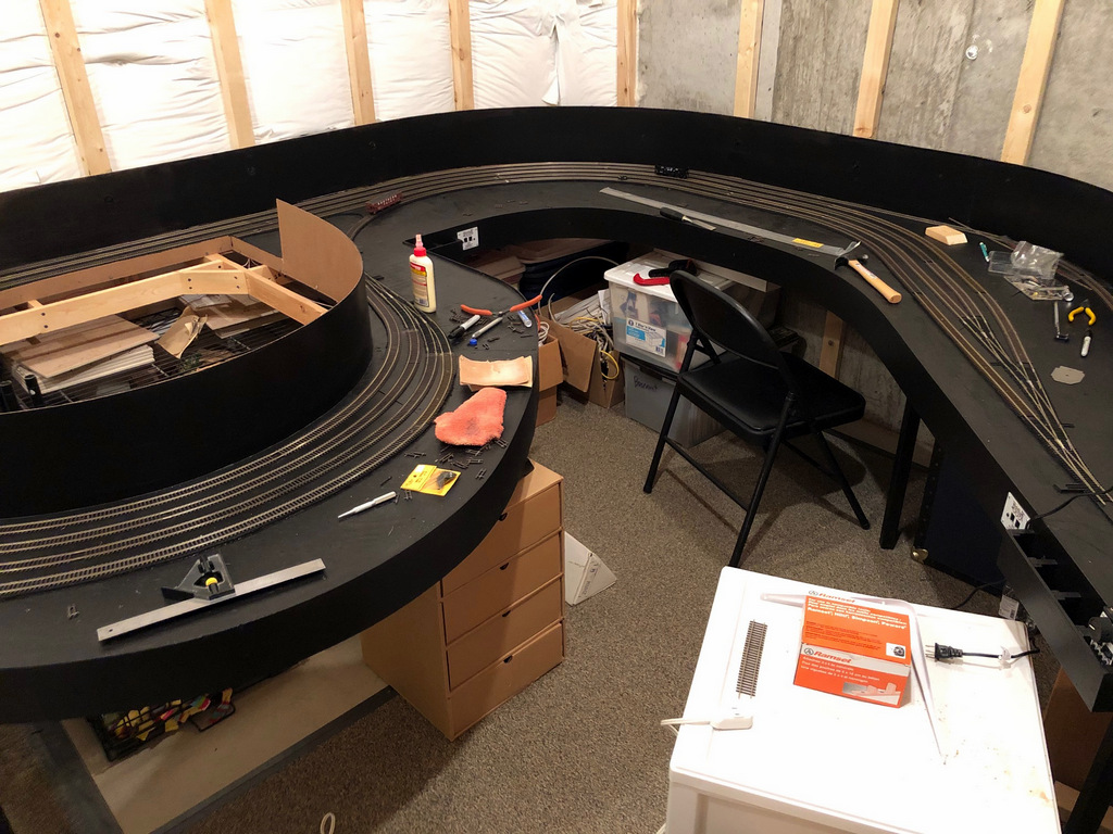
I had to pause on the helix project (you can see it half-built in the corner) because I ran out of plywood and had to wait a while to resupply. That got me thinking, though, that I need to put up a piece of benchwork so I can 1) see where the helix needs to connect, and 2) work the hidden track between St. Charles and Baker/Mayflower in before covering it with the helix. The hidden track will run right on top of this benchwork and under St. Charles; the St. Charles tracks will be about 2-3″ higher.
This piece of benchwork is a little strange in that it’s made of both 1×2″ and 1×3″ lumber. I needed the 1×2″ slimness to get the hidden track as low as possible, and I needed the 1×3″ on the fascia to give me plenty of room for switch controls and more support for leaning operators. It’s built to mirror the staging benchwork below it, so three risers in the middle of the crosspieces help make it sturdy.
I’ll admit progress has been painfully slow lately, but there is progress!
After a couple months of just breaking in the staging level and working out the bugs (and retiring from the Air Force, and going camping, and taking a trip to South Dakota…), I finally starting building again yesterday. I’ve got the first turn of the first helix that connects staging to the wye at St. Charles complete. 1.5 more turns to go.
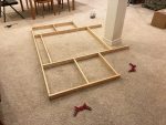
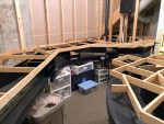
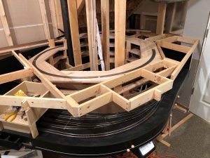
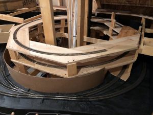
This is the second time I’ve used this method to build a helix, and I really like it. I call it the “double pinwheel”–each level is essentially two layers of 8 identical trapezoids of plywood, each put together like a pinwheel with the two layers overlapping. It’s very easy (once you do the math to figure out your trapezoid and cut a master), it’s very forgiving, and it’s very strong after the glue dries.
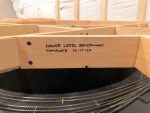
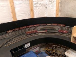
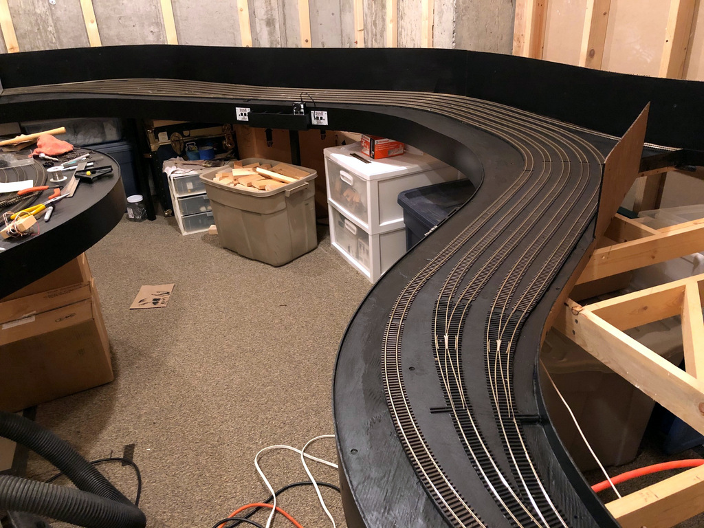
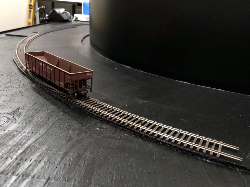
Some particulars on the helix. It’s a 24″ radius helix that gains 4.5″ per turn. That works out to a 3% grade which should work fine for all the trains that will use it. The track you see looping around it (in the black painted area) is the continuous running loop connection. I was able to let a short string of cars run away from the top, and they negotiated the switches without a hitch at warp speed, even the #4 with REALLY short points going into the L&N staging yard you can see in the photo above (phew).
I’ll write a full article on the double pinwheel helix soon as I don’t know of anyone else who uses this method (let me know if you do). In the meantime, here are some progress pics.
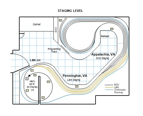
It occurs to me that I’ve been sharing all these pictures that show pieces and parts of the staging level, but I’ve never shared a drawing showing the staging plan.
Staging takes up almost the entire space below the lower level. The notable exception is a large cabinet in one corner that houses tools and supplies and a narrow space next to the cabinet dedicated to the DCC command station, booster, and computer connection. Adjacent to the DCC command station (currently a Digitrax Zephyr Xtra) is a 19″ section of track separate from the layout for programming locomotives. This area also houses two short connected tracks for storing locomotives not in use for a given ops session–I figured this was better than handling them all the time.
The rest of the level contains the two staging yards for the Southern and L&N, respectively. Southern staging, representing Appalachia, VA, consists of three staging tracks on a reversing loop with tracks of 21+ feet. Inman represents the upper end of Appalachia Yard (as it did in real life), and I’m using this moniker to differentiate the “business end” of Appalachia from the reversing loop connection end. A forth track snakes around the reversing loop to form a continuous running connection on the other end of the layout where the helix goes up to St. Charles. I plan to use this to break in new locomotives and to entertain kids–in a pinch it can be used as a fourth Southern staging track.
Tracks on the staging level are now complete. The last piece was the 4-track L&N staging yard shown here.
Under St. Charles is a 4-track, stub ended staging yard for the L&N which represents Pennington, VA where the short Pennington Branch left the L&N’s Cumberland Valley main to connect with the Southern at Pocket, VA (technically L&N Jct), not far from St. Charles. L&N tracks are 13 1/2 feet long, plenty long for the single locomotive and short string of cars that usually plied these rails. Four tracks is about three too many, but this will allow some “fiddle staging” for less commonly used cars (e.g., boxcars) and hoppers from other eras.
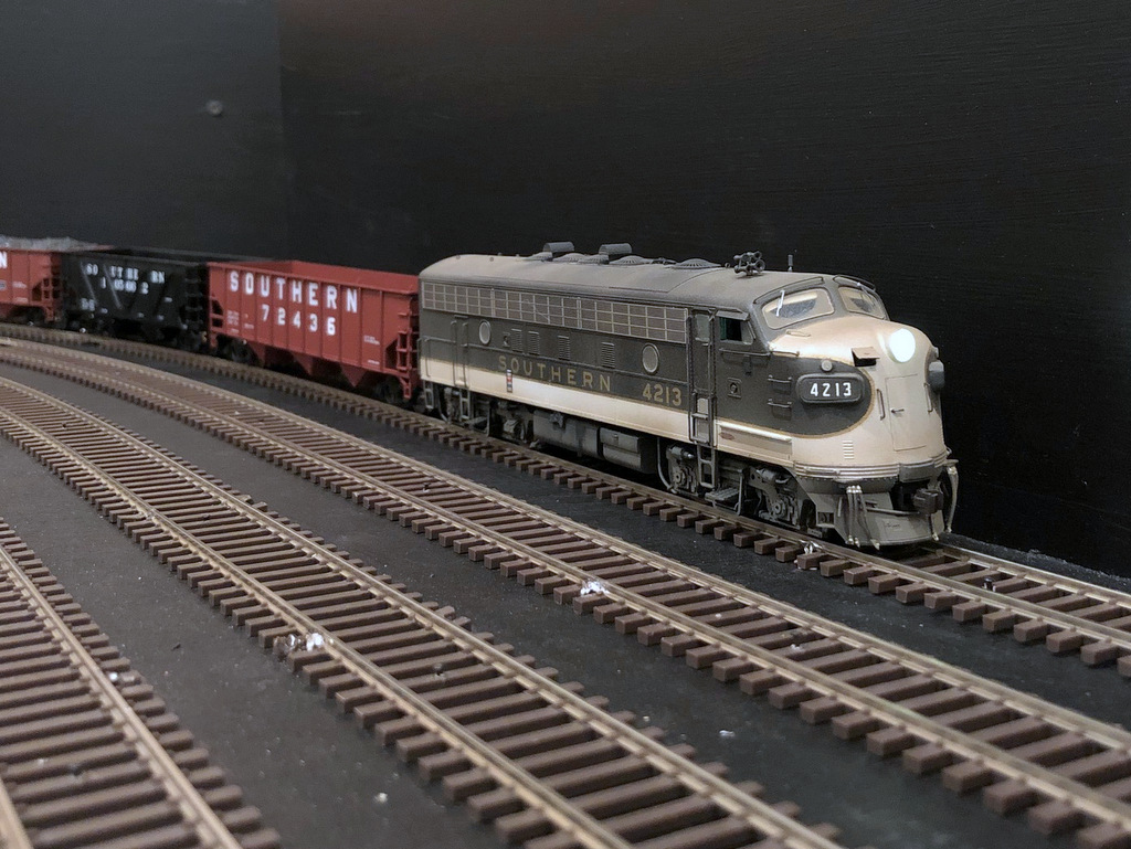
Yesterday, my “benchwork” became a “layout” with the running of the first locomotive. Of course, trusty F7A 4213 was the first locomotive, and my boys did rock-paper-scissors to determine who would be the first engineer. My oldest won, but all three of us got a chance to run around the half of the staging level with completed wiring.
This is the first train to run on the layout on April 17th 2020
My two sons crewed the first train on the layout
Half a train, half a level, and no scenery in sight, but it was still a magical moment to see all that planning and work to this point pay off with a moving locomotive. As a bonus, the hand-laid switches performed well (despite not having their mechanisms in place yet), only a couple of protruding track nails on and excess solder in a couple joints (easily fixed) caused any issues.
I’m more motivated than ever to keep building!!!
My sons do rock-paper-scissors to determine who will be the first engineer
Last night, I put down the “bronze spike” commemorating the completion of track for the staging level. Not that exciting in the big scheme of things, but it is a major milestone in the layout’s progress!
Tracks on the staging level are now complete. The last piece was the 4-track L&N staging yard shown here.
The last piece of the staging level to be completed was the 4-track L&N staging yard representing Pennington, VA. This yard is stub-ended with tracks about 13.5 feet long. This is enough for a locomotive, cab, and about 20-28 hoppers. Based on photos, this will be more than adequate to represent the meager traffic the L&N hauled off the St. Charles Branch. I made it four tracks because I had the space, and this will give me some room to store trains and cars from “other eras” when not being used for a particular operating session.
There is still a bit more work to do before trains can run. I need to put in the switch control mechanisms and drop about 100 feeders to the main DCC track bus under the layout.
In the photo above, taken from the door to the layout room, you can see the Southern staging yard under the mess on the far left, the beginning of the Southern staging yard and end of the L&N stub tracks against the far wall, the Southern main linking staging to the helix (will occupy the open area on the right) along the right aisle, the L&N staging yard, and the continuous running connection entering along the right-hand wall–this last track connects to the Southern main via a switch just out of view in the lower right corner.
Another milestone today–the Southern Railway staging yard tracks are now complete! The yard, representing Appalachia, Virginia, consists of 8 hand-laid switches and about 40 pieces of flex track. The yard is three tracks on a reversing loop, one through track for mainline running (which can be used as a fourth staging track), and two short storage tracks for extra locomotives.
The Southern railway staging tracks representing Appalachia are now complete. The tracks form a reversing loop under the main helix.
The shortest staging track is about 21 feet long–that’s long enough for three locomotives, a cab, and 35-45 hoppers. . . should be plenty. A second, 4-track stub-ended staging yard with shorter tracks will help with L&N trains and holding excess cars.
Here’s one of the insulated joints going from the yard lead to a staging track on a reversing loop. I offset the joints about 1″ which is recommended for better performance of the auto-reverser.
I also fixed a problem with this website where the smaller images weren’t linked to their full-size cousins–that’s remedied now if you’d like to get a closer view of previous post pictures. Thanks to Stuart Thayer for pointing that out!
This is the first section of track on the St. Charles Branch layout. It’s a part of the Southern Railway staging yard representing Appalachia, Virginia.
Yesterday was an eventful day in two ways. First, it was our first day under “stay at home” orders for COVID-19 in Colorado. Second, the extra time gave me a chance to hit a major milestone on the St. Charles Branch–the first sections of track!!!
The first piece was a section of flex track for the Southern Railway staging yard representing Appalachia, VA. I’m hand laying all the track on the visible section of the layout, but I’ll be using Atlas Code 83 flex track for the staging yards, helices and hidden track. The flex track is recycled from my former layout representing the Interstate Railroad’s Dixiana Branch, and I’ve got plenty!
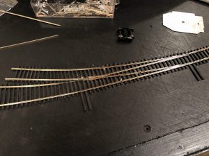
Here’s the start of the first switch in staging. This one leads to two engine tracks alongside the staging. I’m using Tony Koester’s method which is outside-in.
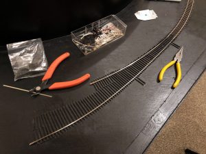
I am hand laying the switches in the staging area, and I started the first two switches yesterday. I’m using the method Tony Koester outlined in Model Railroader a couple decades ago. As you can see, it’s an outside-in method and requires no fancy tools, just rail nippers, needle-nosed pliers, a flat file, a triangle file, a bench vise, soldering iron, and an NMRA track gauge. I’m using Micro Engineering Code 83 rail and small spikes here. The tool set is rounded out with a freight car truck to check things as you go.
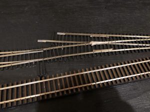
First switch mostly completed. This shows one of the things I like about hand-laying: I can stack the points of the second switch right on top of the frog from the first switch.
It’s been more than 5 years since I hand laid a switch, but I’ve found it’s like riding a bike (I looked but couldn’t find where I’d put Tony’s article, so it was all from memory). One lesson I carried over from my previous layout is to pay special attention to two things on the frog: 1) make sure the track is at the tightest acceptable gauge at the frog, and 2) take extra time to make the rails line up perfectly with the point of the frog.
The staging level got a coat of black paint to prepare it for track. This panoramic view of the layout room shows the start of L&N staging on the right and the peninsula for Southern staging on the left.
While I’d never call COVID-19 a good thing, it has made for a lot more time at home and accelerated progress on the layout. Yesterday, I accomplished a major step by painting the entire staging level black. I chose black for the fascia and staging area for two reasons. First, black helps things hide that might otherwise be distracting from the main layout, and second, I’m modeling the coal fields, so black just fits. Not to mention, it’ll look really nice with locomotives in Southern’s tuxedo scheme! I’m very happy with the way the curved Masonite fascia looks in satin black. . . Darth Vader would be proud. I’ve heard people complain that you can’t fill gaps in Masonite, but I found lightweight spackling compound (the kind used to fill nail holes in drywall) works great. I was able to repair a few accidental gouges from a circular saw quite well. The most exiting thing about this step is what it means next–track! I should be hand laying my first few switches this week and laying
These pictures give you an idea of the large amount of staging I’ll have on the layout–probably 2-4x what I need, but better too much than too little. In the first picture, you can see the ties for the switches that mark the entry into the four stub tracks of L&N staging representing the town of Pennington. The Southern will hug the aisle on the right, and the staging yard representing Appalachia will begin just above the green container on the floor and form a reversing loop around the peninsula.
This is looking back under the stairs where the helix to St. Charles will sit on the unpainted lumber. The staging level will have a single track that loops around the back here to create a continuous running loop on the staging level since I won’t have one on the upper levels.
The second photo shows the layout’s other loop which will allow for continuous running on the staging level. I didn’t have this in the original design, but I was inspired by my young nephew’s visit to try to have something running in a circle for him to enjoy (he LOVES trains). Unfortunately, I didn’t have anything running by the time he visited, but I still thank him for inspiring this modification–I think it will pay dividends in the future for breaking in new equipment and entertaining kids. And hey, sometimes you just want to run trains in circles.
View of the overall layout area with the subroadbed for the staging level complete
Nothing too exciting for this update, but I am making steady progress. Last week I was able to finish all the subroadbed (7/16″ ply with 1/4″ “doorskin” under the tracks) for the staging level. Next step is adding some Masonite walls behind the roadbed to hide the studs and keep cars from falling.
Three of the first five turnouts to receive their ties on the layout
Today was exciting because I got to lay the first ties on the layout! While staging tracks will be prefab flex track, the switches will be hand-laid like the rest of the layout. You can see from the photo some of the benefits of handlaying–how else could I make this cool curved staging yard lead on an S-curve!
I wish this meant I was just days away from laying the first rail, but the ties are really just in preparation for the black paint that will be used for the staging level–better to paint the ties black with the rest than to glue them down onto paint.
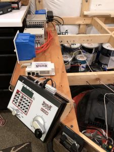
Key Digitrax components on the layout including a DCS51 command station, PR3 computer interface, DCS100 (acting as a booster), and power supply
The last couple of weeks I’ve been working on the fascia and wiring for the staging level, and I’ve also installed the DCC system. It’s a lot easier to install when there isn’t a lot of layout in the way, and most of it resides on the bottom deck anyway.
I’m using the Digitrax DCC components from my last layout. While I have an upper-end DCS100 “Chief” system, I’m actually using a smaller, entry level DCS51 Zephyr Xtra as my command station. While the Zephyr doesn’t have the same functionality as the Chief, it’s got everything I need, and it’s much simpler to operate. Like my previous layout, I’ve mounted it on the fascia where it’s easy to access and can be used as a throttle for the staging tracks or for smaller visitors.
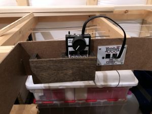
One of the simple throttle pockets for the Digitrax UT4D wireless throttles. It’s designed to hold two throttles while preserving batteries and protecting buttons.
The rest of the throttles are UT4D 2-way wireless throttles connected through a UR92 wireless receiver/transmitter. Even though everything’s wireless, I still use several UP5 throttle plug-ins around the layout. This allows someone else to bring and use their favorite Digitrax throttle, and it allows an ops session to go on if the wireless is acting up. Each of the panels has an adjacent throttle pocket that perfectly fits the UT4D throttles (those who visited my last layout will recognize these). This not only gives the operators a convenient place to set the throttles, but it protects the buttons and also promotes the plugging in of throttles when not in use to preserve batteries.
I’m using three sources to power components. The first is straight wall power, and this powers the UP5 panels to supply keep-alive power to the throttles (preserves batteries while the layout is off). The second is switched power for the DCS100 and UR92, and the third is switched power for the Zephyr command station and a PR3 computer interface. I kept these separate so I could turn on just the “Z” and PR3 when I’m programming locomotives.
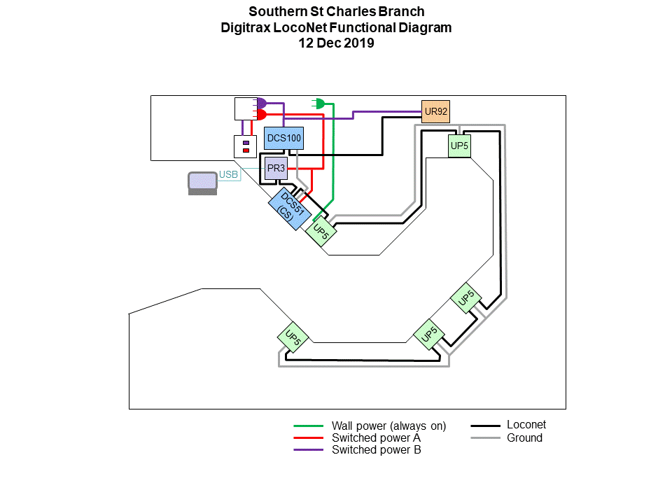
Functional diagram of the Digitrax setup on the layout
One lesson I learned from my last layout was to keep a functional diagram of the Digitrax setup so I could easily determine how the components are wired together even when they’re covered by the layout–it’s a great aid in troubleshooting!
The staging level benchwork took just under a month start to finish. I guess I could have finished it in about two days if I didn’t have a job or family. . . a month’s good.
First, I want to apologize to all of you who so kindly posted comments just to have them not show up! I hope I’ve fixed my settings now to get notifications so I don’t leave anyone hanging again. The comments are there now, so thanks for your patience!
The benchwork for the staging level is now complete. I was worried that I would run out of pieces of 1×3 from the old layout, but now that I’ve built an entire level of benchwork, I’m not worried about that at all. The layout is small enough that it really doesn’t take that much lumber to frame a level.
The next step will be installing the basic wiring bus and plywood for the staging tracks.
This was the trickiest portion of the benchwork because I had to build it around an existing stud wall. The wall does provide a great way to support the layout, though.
Here’s a look at the benchwork for the two “blobs” where the circles will go and the aisle between.
Today was a big milestone on the St. Charles Branch–I installed the first sections of benchwork! I’m building open-grid benchwork from 1×3 lumber recycled from my previous layout. I started with the staging level (~30″ above the floor) at the reversing loop.
Two is better than one
Making some progress
The first four pieces of open-grid benchwork are in. This will house the staging yard set on a reversing loop under the helix.
The layout is going into an unfinished space, and I don’t want it to look so unfinished when everything is done. Most of the walls will be covered with layout, but there’s one corner by the entrance that will be exposed. I’ve never done any framing or drywalling, so I figured “how hard could it be?”
Here’s how the entrance corner of the room looked when I started. This area is the only part of the room that won’t be covered in layout, so I wanted it to look a little nicer.
The studs along the wall were already in place, so all I had to do was build a frame around the steel beam (pretty straightforward. Now for the drywall. I watched a lot of YouTube which helped, but nothing can quite prepare you for heaving a full sheet of drywall over your head and holding it while you try to put enough screws through the board into wood to keep it there. Despite my best efforts at marking the studs, I missed enough to have the drywall ignore the screws that were secure and come dropping back down on my tired arms–I came up with some pretty creative non-cuss words to share my joy! Thankfully the walls were MUCH easier!
YouTube was again my friend when it came to taping and mudding the drywall. If nothing else, it at least helped me get the right tools for the job, and I found it a moderately soothing chore. A little sanding, a little spray texture and a little gray paint, and the corner mostly looked like it was finished with the rest of the house.
I added a frame around the steel beam in preparation for drywall
After the drywall installation but before the mud and tape
The corner is nearly finished–just need some trim and carpet
Here’s the rest of the room where the layout will go. I’m using 2x3s set into the concrete to hold the layout
I also needed a way to anchor the layout to the concrete wall that made up about 2/3 of the room. I decided to use 2x3s spaced about 18″ apart and set into the wall with nails fired from a Ramset. They’re quite secure!
The final pre-layout touches included installing a couple of cabinets and a counter top I’d picked up from a local recycling store and adding some carpet. For the carpet, I just used a roll of surplus industrial carpeting 4′ wide and laid it down with some carpet tape in the areas where the aisles would be. There’s still some trim work to do, but the room is ready for some benchwork!