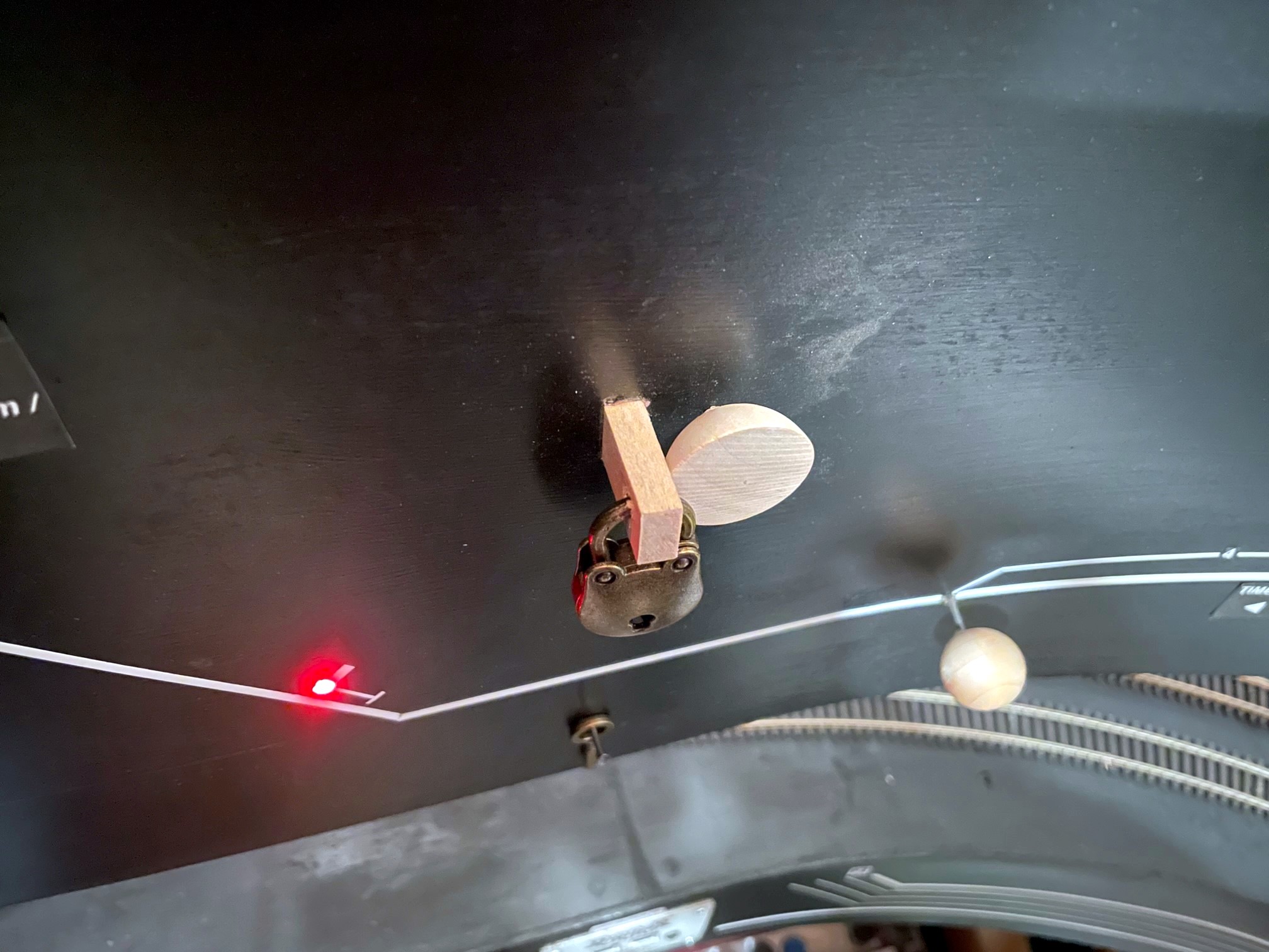
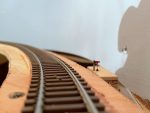
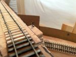
The Black Mountain Local stops to reset the dwarf semaphore now that their work is complete
Semaphores were a common way of signaling trains on the Southern Railway. Semaphores were often used at stations to indicate whether or not the train was cleared to proceed or needed to stop (or at least slow down) to pick up orders. Semaphores were also used to protect branches when trains were working on them, and these semaphores were usually set by the crews themselves. The St Charles Branch employed three such semaphores to protect the lines RR west of St Charles. Here’s the exact verbiage from the Employee Timetable:
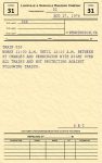
“At points shown below, semaphore signals will govern the movement of trains and engines. When track is not occupied, signal will indicate proceed. When in either position, stop or proceed, signal will be fastened and locked with a switch lock. When indicating stop, position will not be changed until train or engine occupying the track clears it and the crew of same restores signal to proceed indication. West of St. Charles—located at the junction between Bailey Trace and Fawns Branch lines.”
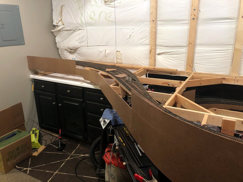
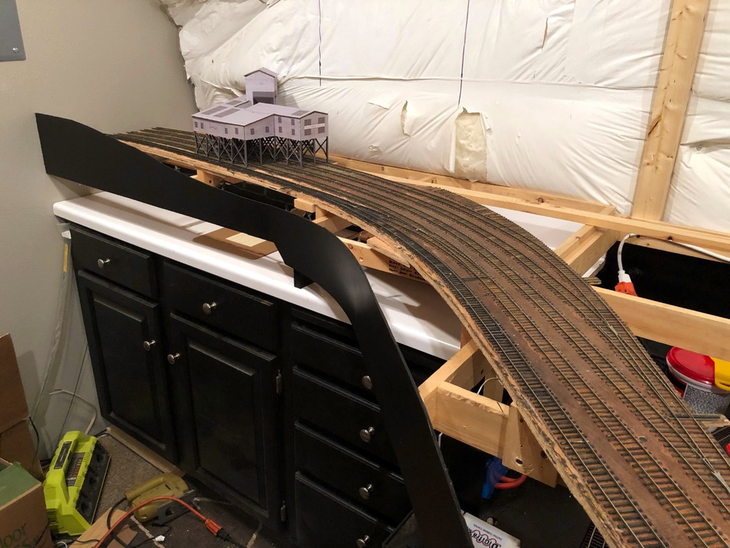
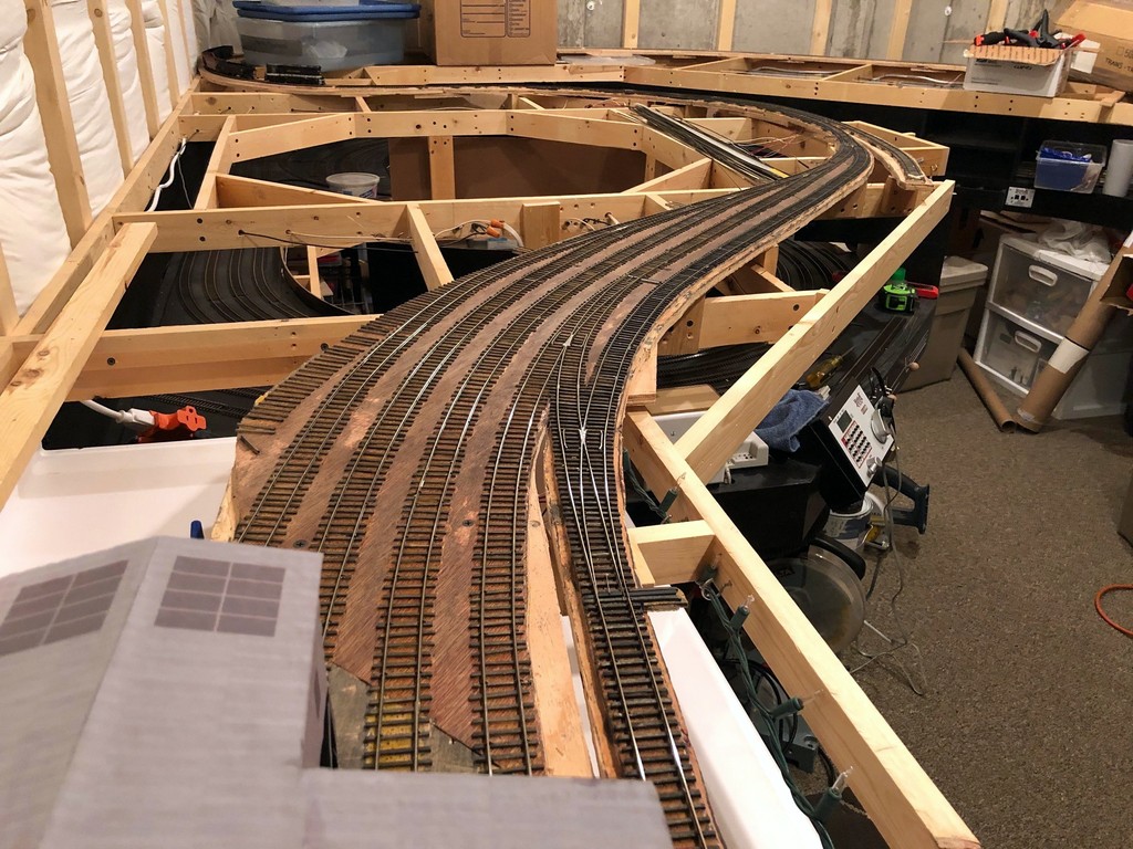
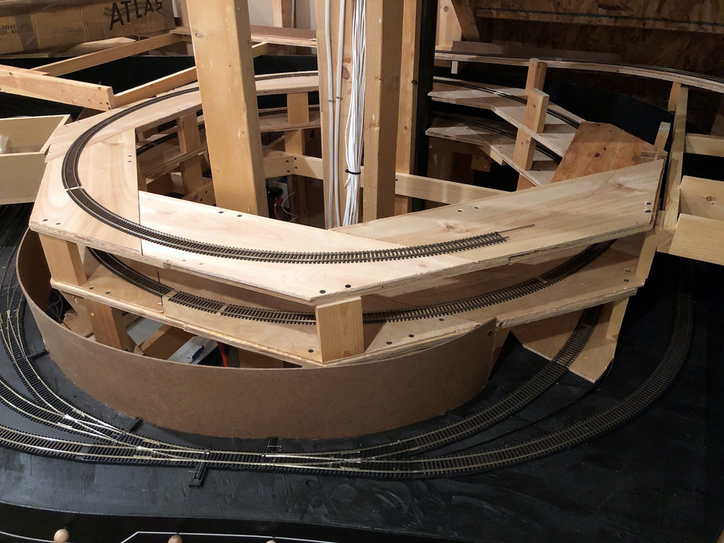
I definitely wanted to model this aspect of operations, and as a bonus, two of the locations of these semaphores correspond with long sections of hidden track on my layout, the hidden track between St Charles and Mayflower on the Bailey’s Trace Branch, and the helix between St Charles and Turner’s Siding on the Black Mountain Main. These would not only serve the purpose of adding more prototypical operations, but they would also serve a very practical function of protecting trains that can’t be seen without a dispatcher.
I learned from a former Southern employee who worked in this area that these were “dwarf semaphores.” I haven’t been able to find a picture of one of these exact devices near St Charles, so I Googled “dwarf semaphore” to see what they were all about. They operate just like the tall semaphores and come in both upper- and lower-quadrant designs, and most have lights. They only sit about 3-4 feet tall, though, and have a blade somewhere around 14″ long–that’s super tiny in HO scale! I picked a Union Switch and Signal upper-quadrant, two-light design. I didn’t see anything resembling this available in HO scale, so I set about building my own operating version from sheet brass and wire.
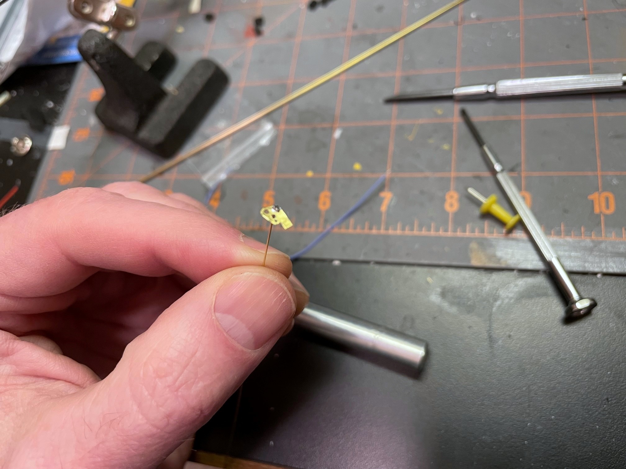
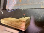
Faceplate and blade made from brass with the swivel wire soldered in place
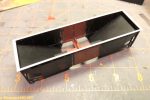
I made a drawing of the blade and faceplate with the lights, sized it down to HO scale, and printed it on sticker paper. After sticking it to a sheet of .005″ brass, I was able to drill holes for the lights, swivel and actuating arm and then cut it out with scissors. After cleaning it up with a file, I bent a piece of .015″ brass wire, inserted it through the swivel hole, and soldered it to the faceplate. I drilled a hole for the wire through a piece of 1/16″ brass tubing for the base. I wanted to use fiber optics for the lights, so I soldered a 1/16″ long piece of tube to the tall tube angling up to where the light would be to hold the fiber optic strand. I painted the faceplate and tubing black, then made lenses by melting the end of a piece of fiber optic into a mushroom shape holding it near a soldering iron. A little red for the blade and a white sticker stripe and the faceplate was complete.
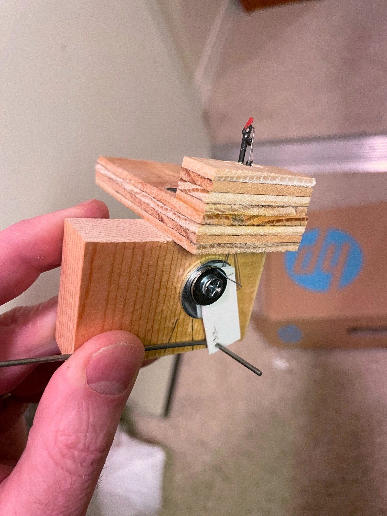
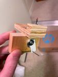
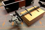
Completed dwarf semaphore model and lever mechanism
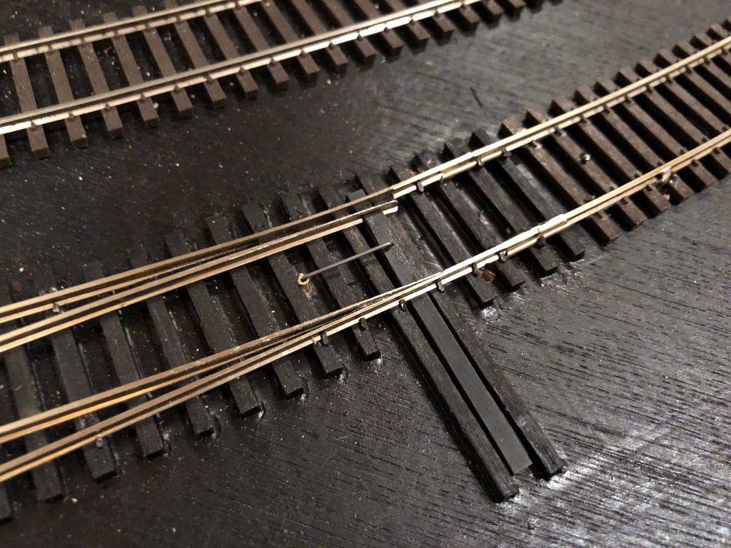
I mounted the base post in a piece of plywood and drilled a hole for a second piece of 1/16″ brass tube underneath the blade for the actuator arm. After inserting the faceplate and securing it with a bend on the back side of the tube, I had a faceplate that swiveled freely. A piece of .012″ steel music wire bent at a 90 degree angle at the end was inserted into the blade and the tube for the actuating arm. On the bottom, I made a lever for the actuator that raised the actuator just slightly while allowing for significant travel for the longer actuating rod connected to the fascia. I filed the end of a fiber optic strand so it would be parallel to the faceplate and inserted it into the little brass holder and through a hole in the base. A little silver paint for the post, and the tiny dwarf semaphore was complete!
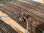
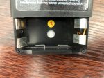
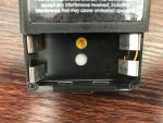
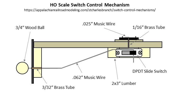
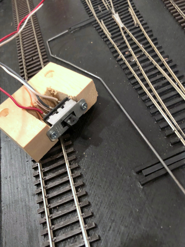
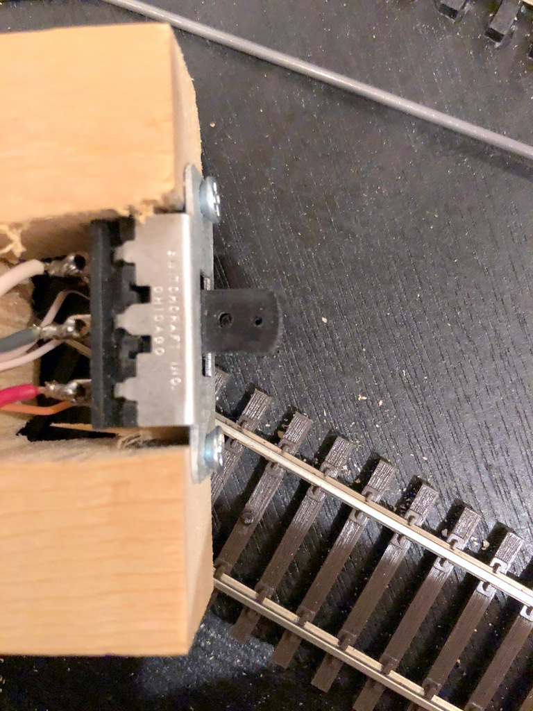
One of the things I wanted to model was the use of switch locks. I found some Miniature Locks on Amazon that suit this purpose perfectly! I decided to use a slide-switch mechanism like I use for all my switch controls, but I needed a longer slide to enable the lock to go in front of and behind the control knob to “lock” it into either position. I found some old three-position slide switches on eBay that did the trick! The slide switch serves two purposes–it “snaps” into position to hold the control and semaphore securely in position, and it allows for the routing of power to LEDs, in this case some bi-color red and green LEDs that change color when the polarity is reversed, something easy to do with a slide switch. After mounting the switch to the layout using a piece of 1×4″ board, I drilled two holes in the slide handle and used .o62″ steel wire to connect the slide to the lever under the semaphore and a separate rod through the fascia for the control knob, a 1/2 ball piece of wood.
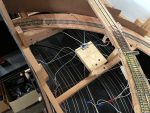
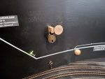
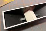
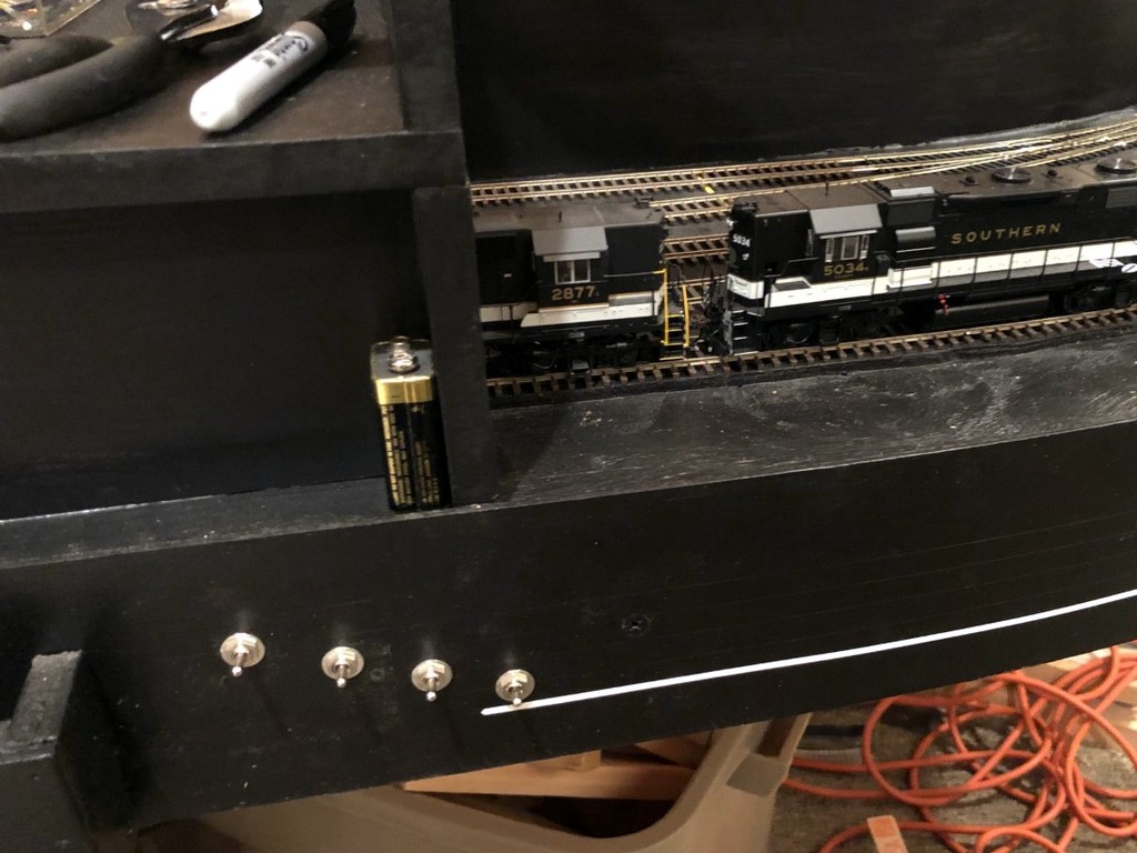
Semaphore control in the “stop” position showing the red fascia indicator and lock
For the lock mechanism, I used a bar of 1/4″ x 1/2″ basswood with a hole drilled for the lock and inserted it through a hole in the fascia and benchwork adjacent to and just touching the control knob. The hole sits just ahead of the control knob when it’s pressed in and just behind it when pulled out. I also connected two LEDs to the slide switch and a 12V DC power supply. One LED is mounted behind and just through the fascia to serve as an easy indicator for the full-size operators. The second was inserted into a hole drilled in the semaphore base where it can shine into the fiber optic strand.
The result is a semaphore with working lights, blade and a switch lock. While the dwarf semaphore sits about 3′ from the aisle and is tough to see, it is pretty cool to have an operating model and a tiny little red or green glow that matches the indicator on the fascia. Now the operators on the St Charles Branch, just like their real-world counterparts, have to stop at the semaphore, unlock the lever, change the indication, and re-lock the lever before proceeding up the branch (and do the reverse on the way back). While I’m not sadistic enough to make operators lock and unlock every switch they need to throw, working with switch locks a couple times during a session is one more step toward replicating the actions required on the real thing, and it adds a little prototypical time to the work required. Oh, and it helps protect trains without a dispatcher which is pretty useful.
[Note: since I first published this post, I decided to reverse my control mechanism so “proceed” is pulled out and “stop” is pushed in. It just required me to reverse the lever used to lift the arm. I figured having the crew move the lock to the front of the pull knob where it’s more obvious makes more sense.]
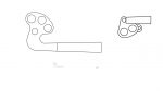
My PowerPoint drawings of semaphore blades and their HO scale counterparts
Faceplate and blade made from brass with the swivel wire soldered in place
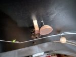
Close-up of the mostly complete dwarf semaphore made from brass and fiber optics
Completed dwarf semaphore model and lever mechanism
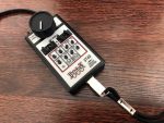
The three-way slide switch wired up–the short leads are for the LEDs, the long leads connect to 12V DC
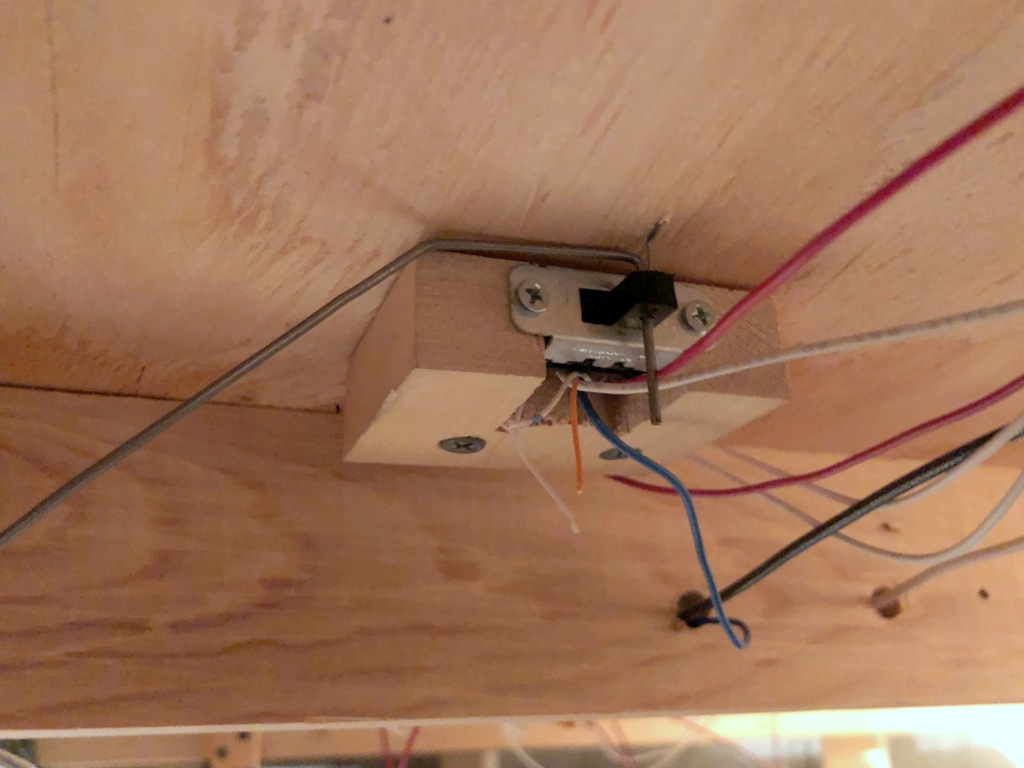
The internal guts of the control mechanism showing the two control rods routed through the handle of a slide switch
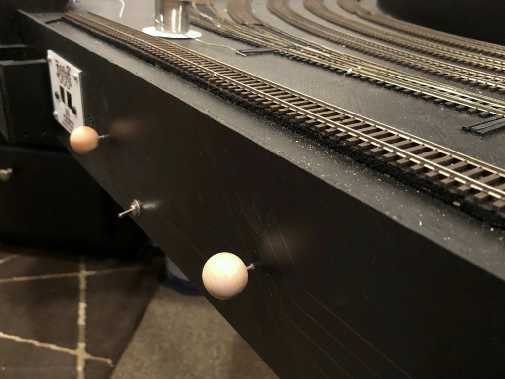
Two holes in the fascia, one for the control rod and one for the locking bar
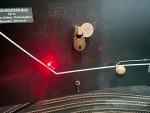
Finished dwarf semaphore in the “stop” position–note the red light
The Black Mountain Local stops to reset the dwarf semaphore now that their work is complete
HO scale dwarf semaphore in the “stop” position
HO scale dwarf semaphore in the “proceed” position
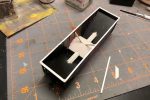
Semaphore control in the “proceed” position showing the green fascia indicator and lock
Semaphore control in the “proceed” position showing the green fascia indicator and lock
Semaphore control in the “stop” position showing the red fascia indicator and lock
Semaphore control in the “stop” position showing the red fascia indicator and lock
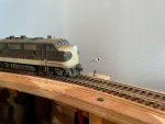
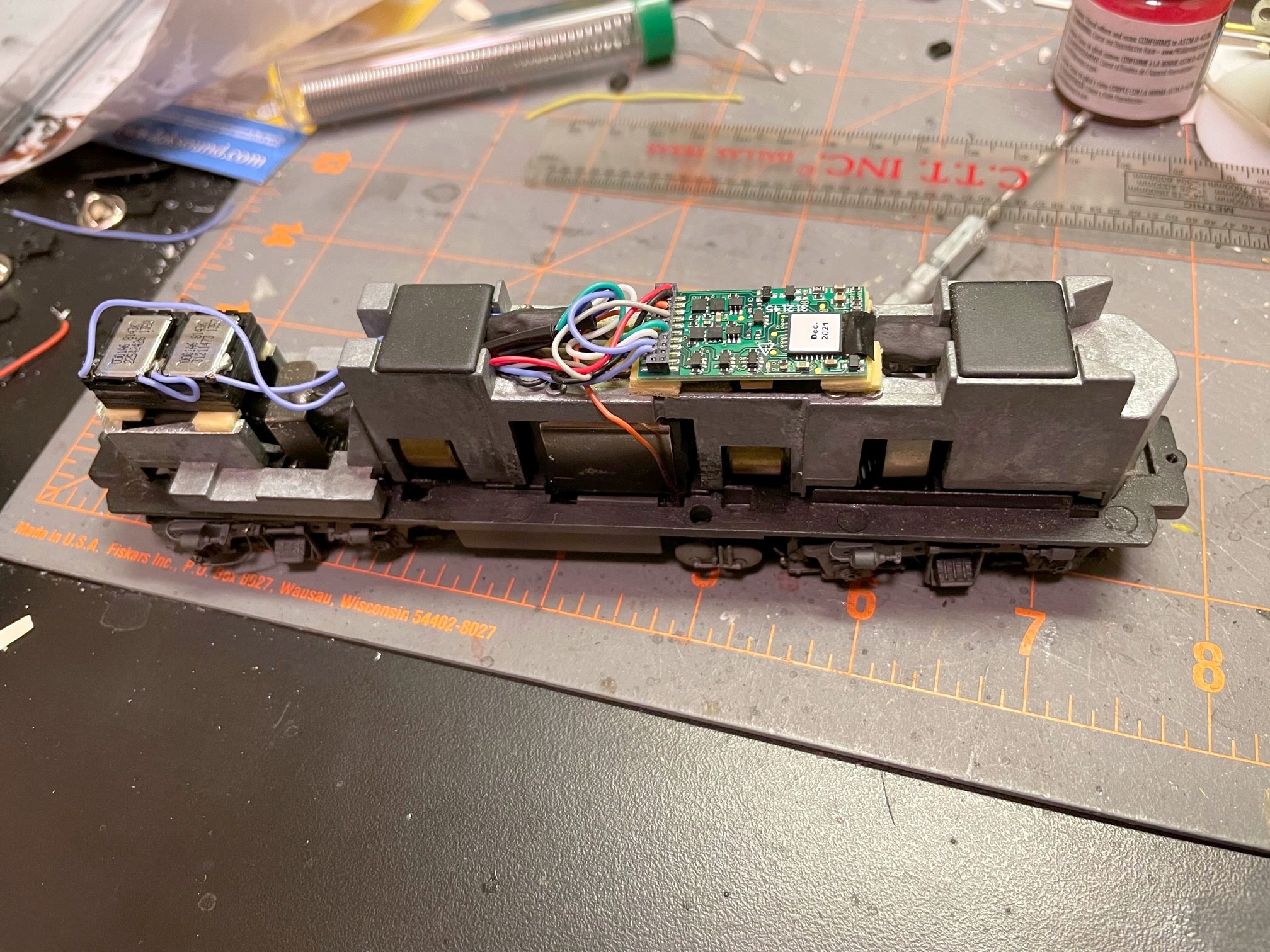
You may remember Southern GP7 2187, a Proto GP7 I finished last summer. Well in addition to fixing the railings and steps for my 1970 timeframe (black and white instead of yellow), I decided to install sound. Now sound is something pretty new and intimidating to me, but after running a couple factory-equipped sound locomotives, it was tough to go back to no sound. I finally decided to just jump in! There are many great sound decoders out there, and everyone has their preference. I won’t claim to be an expert, but after doing some research, I decided to start with some Soundtraxx Econami decoders. As you might guess from the name, these are “budget” decoders that run about 2/3 the cost of a full-featured sound decoder from any manufacturer. The Econami is pretty basic, but it does have the key features I need, and it uses the same basic sounds as the more expensive Tsunami 2s. Best of all, the Econami Diesel version allows the user to select from a handful of prime movers including everything I need for my first-generation fleet: the Alco 244 for RS3s and the non-turbo EMD 567 for Fs, GP7s and GP9s.
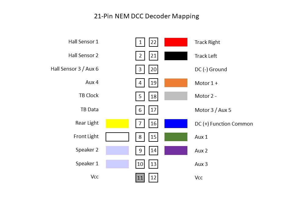
Basic mapping of a 21-pin connector for DCC (use at your own risk)
Soundtraxx makes two versions of the diesel Econami, the larger ECO-PNP and the smaller 21-pin ECO-21PNEM. I picked up a couple ECO-PNPs, one of which was intended for 2187, but once I got the decoder, it was obvious that it wouldn’t fit without major modification to the large metal weight–I needed something smaller. After installing the PNPs in an RS3 (just barely) and an F3A, I decided I was happy with the sound produced by the Econami and a pair of mini cube speakers, so I looked to see if I could install the smaller 21-pin decoder in the GP7. The 21-pin arrangement is newer, and I was surprised at how tough it was to find a cheap 21 pin harness I could wire into the locomotive. You can find cheaper ones in Britain, but it was going to cost me an extra $20 to get one in the states–what’s the point of using the Econami if a simple harness was going to eat up all the savings?
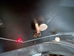
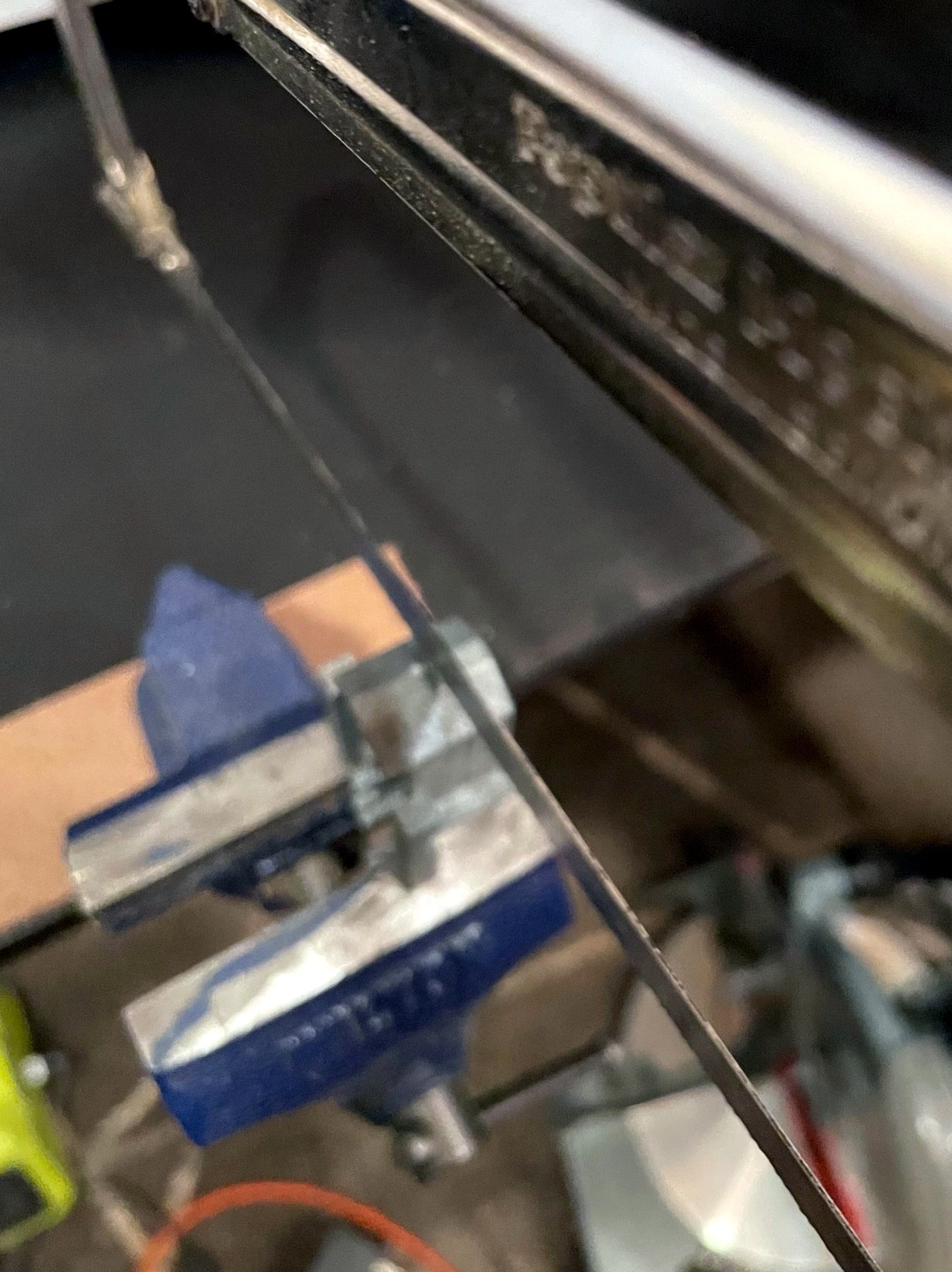
Taking 8mm off the height of the weight in the nose of the Proto GP7 to make room for speakers
So, could I get the 21-pin Econami to work without a harness? While it was a little tough to find info, I finally figured out the mapping of the 21 pins (thankfully German shares some commonality with English…). I knew it wouldn’t be practical to solder directly into the decoder (the pin holes are tiny and close together), but I thought I might be able to shape the wires to act as pins, so I ordered up an ECO-21PNEM. What I found was I could tin the wires on the locomotive, cut the end so about 2mm of metal was exposed, and then carefully insert the wire into the correct pin hole. While the connection is not bulletproof, it’s snug enough that the wires don’t come out easily, and if you can push the wire in until the insulation is flush with the board, there’s little chance of a short. For the extra wires (e.g., speaker wires), I used 30 AWG stranded wire tinned with solder–I had to use a little extra solder to get a snug fit, so a 28 AWG wire would probably work as well. Once I verified everything worked, I used a piece of electrical tape to hold the wires down and in-place.
Using a 21-pin Econami decoder without a 21-pin harness
Now for the speaker. Unfortunately, I decided to use the large clear plastic blocks for the number boards and lights, so the little room that was left in the top of the shell was taken up. I decided the best course of action was to take the weight off and remove about 8mm of metal height from the nose section with a hacksaw. After filing the cut clean, I was ready to install the speakers. I’m using the 11 x 15mm cube speakers made by Loksound. You can find a lot of sources for speakers this size, but I love that the Loksound versions come with different baffle arrangements including both short and tall and a base to install two speakers side-by-side (my preference). I built a double baffle with the short walls using CA and connected the speakers in series (16 ohms impedence). Yes, the decoder is 8 ohms and the speakers are 16 ohms. My research leads me to believe this is not ideal but is acceptable as long as I don’t run the amp at max, which I don’t–if you have a good technical reason why this is not a good idea and will damage things in the long-run, please feel free to post a comment!
So, in the end, I was able to fit a sound decoder and two small speakers into the Proto GP7 with just a small, one-cut modification to the body weight, and I’m really happy with the sound! I’ve got a Soundtraxx Tsunami 2 EMD diesel decoder now as well, so I’ll do a comparison at some point and let you know how I think the Econami compares. For now, I’ll enjoy the chugging sounds of the EMD 567 and hauling coal hoppers interrupted occasionally by the chimes of a Nathan M5! St Charles is now a much louder place.
Operations, in my own words, is simply the means by which a railroad – or a layout – moves things to the intended location while keeping trains from colliding over a shared set of rails. Paperwork is an important part of railroading operations, so it stands to reason that paperwork should also be an important part of any operations-oriented layout. No one REALLY loves paperwork, though, so how much is enough? There are as many answers to this question as there are operating layouts, but I’ll share what I’ve settled on because I believe it strikes a pretty reasonable balance and works well for a sleepy coal branch layout like mine.
Everything the St Charles Local needs to operate on the layout
My goals for the layout’s operations:
Replicate essential elements of the prototype’s operation
Make paperwork realistic without being overwhelming (and avoid tedious paperwork that serves no modelable purpose)
Make it easy for operators to work their trains like the prototype and get the cars to the right place with minimal training
Avoid creating any boring jobs on the layout (a dispatcher would be a boring job on this layout and thus would always fall to the host)
No car cards (I realize I’m tipping some sacred cows here…)
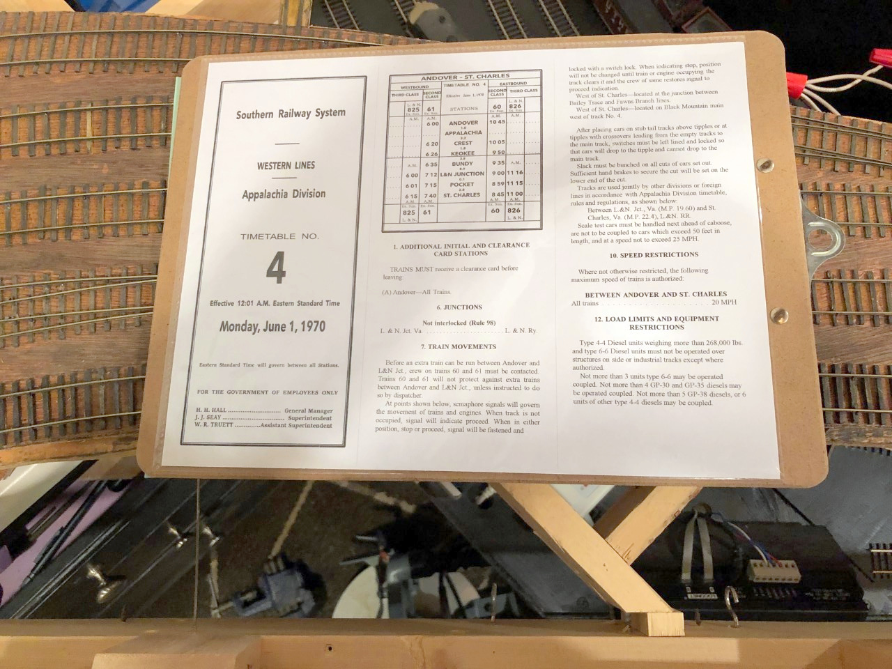
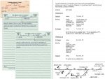
The first step was to understand operations on the prototype St Charles Branch. To help, I had photo captions, excerpts from articles, and some notes from individuals who worked in the area, but the real score was an Employee Timetable (ETT) of the Southern’s Appalachia Division circa 1970. Employee timetables are a critical piece of paperwork on the prototype. They list the scheduled trains for each line, the “class” of each train, the stations they run through, and their scheduled arrival times for each station. In a timetable and train order operations scheme, lower class or unscheduled trains (extras) must keep clear of higher priority trains in the timetable. While the timetable sets the basic scheme of operations, the dispatcher uses train orders for each crew to handle the details, telling them where and when they can work, what trains they need to meet and where, etc.
The Southern’s Appalachia Division dispatcher controlled far more than just the St Charles Branch, so a dedicated dispatcher for my railroad that employs 2-3 operators per session and no more than 2 trains simultaneously would be overkill. In the name of “avoid creating any boring jobs,” I wanted to see if I could completely simulate the role of the dispatcher in keeping the trains moving and separated without actually having a human playing the dispatcher on the layout.
Part 1. Moving the Trains
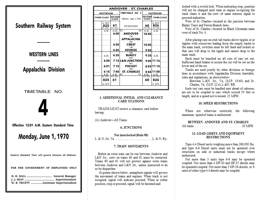
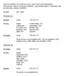
Employee Timetable
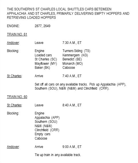
The Appalachia Division timetable listed one Southern second-class train each direction from Andover (the main coal-field yard near Appalachia, VA after 1965) to St Charles daily except Sunday (same crew with a different number for the outbound and return trips) along with one third-class L&N train each direction from L&N Junction to St Charles. All other trains, including the “St Charles Switcher”/”Black Mountain Local” mine runs out of St Charles would run as extras and have to steer clear of the scheduled trains.
Additionally, timetables list all the unique rules and procedures for that division including things like speed limits (20 MPH for the whole St Charles Branch) and instructions for working specific sections of track. One of the interesting sections in the Appalachia Division ETT reads as follows:
“At points shown below, semaphore signals will govern the movement of trains and engines. When track is not occupied, signal will indicate proceed. When in either position, stop or proceed, signal will be fastened and locked with a switch lock. When indicating stop, position will not be changed until train or engine occupying the track clears it and the crew of same restores signal to proceed indication.
West of St. Charles—located at the junction between Straight Creek and Gin Creek branches.
West of St. Charles—located at the junction between Bailey Trace and Fawns Branch lines.
West of St. Charles—located on Black Mountain main near east end track No. 5.”
I had heard about one of these semaphores from a former Southern employee who once worked in the area, but now I knew exactly where they were located and how they were used. This was perfect for my layout because I could use two of the three semaphores to protect long sections of hidden track (e.g., the helix between St Charles and Turners Siding), and best of all, the crews do the work to protect themselves on these lines without the need for a dispatcher or hard-to-model procedures like a fusee or flag.
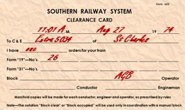
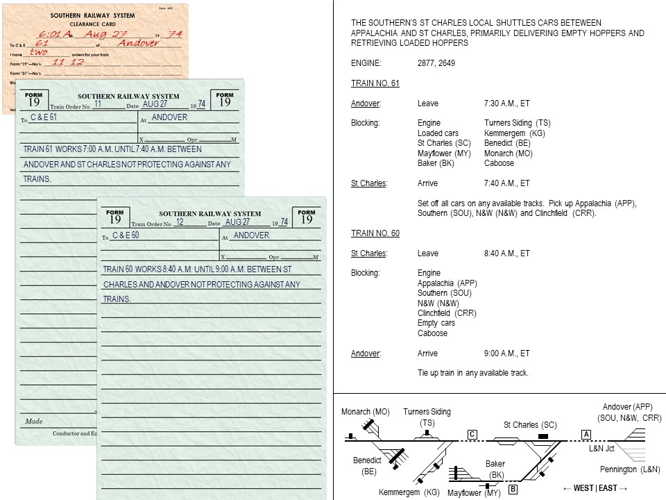
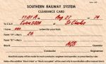
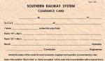
Clearance card showing how many orders the crew has
Even with these semaphores, trains still used orders giving them clearance to run. Train orders give crews instructions and authorization to occupy certain sections of track and to meet other trains. The dispatcher issues the orders to the conductor and engineer of each train, and the orders can be given over the radio or passed along to the crew by an operator at a station along the way (this was the primary use of semaphores at Southern stations–to tell a crew if they could proceed or needed to slow or stop or pick up orders). I’m no expert on orders, but the two common orders on most railroads are the Form 19 and the Form 31, similar forms in content, but crews needed to stop and sign a Form 31 while a Form 19 could be issued “on the fly.” The Southern seemed fond of the Form 19 while the L&N seemed to use more Form 31s, so I decided to use both. With no dispatcher, I also decided crews would start their jobs by receiving orders telling them their clearances and any other special authorizations or provisions. The practice of picking up orders before moving the train is prototypical, but of course, the train orders were not enough paperwork for the crews by themselves, so the Southern (along with other railroads) required all crews to have a “clearance card” before departing. The clearance card tells the crews how many orders they have and the order numbers for accountability–paperwork, after all, is all about authority and accountability.
So, to get trains working when desired and to keep them from colliding, I would need a timetable, clearance card, train orders, and a couple of semaphores. The actual Appalachia Division Timetable is more than 20 pages long, but I really only needed the sections that 1) apply to the St Charles Branch, and 2) apply to model operations. I’ve created a very condensed, single sheet version of the Appalachia Division ETT which has a cover (having it LOOK like a timetable is important to me), a simplified recreation of the timetable for Andover-St Charles, and instructions such as speed limits, use of semaphores, etc. that would be relevant to a model operator. I used the exact verbiage from the Southern timetable in most places, so it has the “feel” and function of the real thing without requiring an operator to read a 20-page document before running their train. To give it even more authentic feel, I took the time to match the the fonts and formatting as close as possible to the real thing–this took a long time, but I feel it’s well worth the effort. While Microsoft Word or Publisher may seem like the best programs to use, I find it’s far easier to build complex documents in Microsoft PowerPoint where I can control text boxes and shapes better. By taking the time to match the feel of the prototype ETT, the layout’s timetable becomes more than just a source of essential information on schedules and rules; it’s one of many parts designed to transport an operator into the layout’s time, place and purpose. It reminds them they’re working on a piece of the Southern Railway, that their operation is part of a larger “Appalachia Division,” that they’re running a part of a transportation system and not a toy, and their train’s purpose extends beyond the modeled portion of the layout.
My one-page recreation of an Employee Timetable for the St Charles Branch
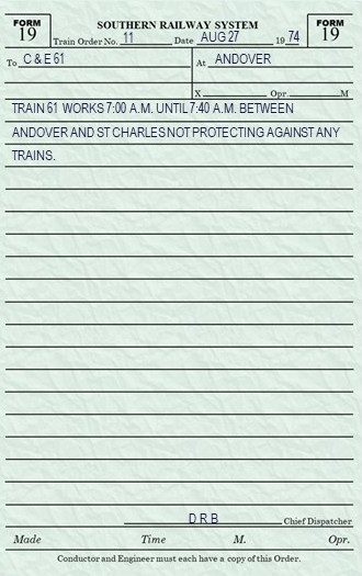
Train Orders
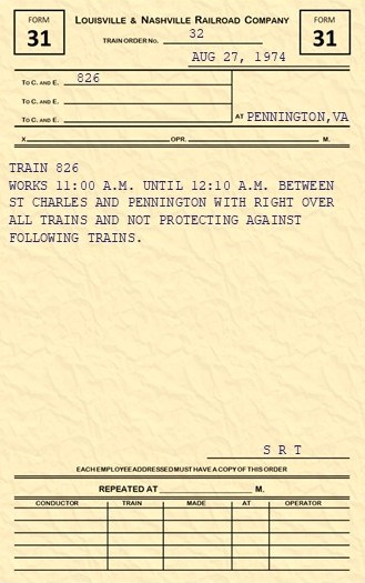
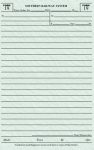
An example of my model Southern Form 19 train order
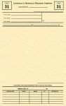
With the timetable in-hand, I now turned to train orders. Because there are very few trains running simultaneously on the St Charles branch, a single set of train orders would likely be sufficient for each train, and because all trains start at a “station” which, in reality, had an operator who could hand orders to the crew, it would be realistic to hand the orders to the crew when picking up the train. To create the train orders, I found images of actual train orders from my era online to use as examples for both the Southern and L&N. Train orders were often given in very simple and standardized language–easy to recreate and easy for a model operator (i.e., non-railroader) to understand. The Southern’s Form 19s were hand-written or printed in bluish ink on semi-transparent green paper, so I use a little color and underlying texture for my rectangle shapes to get this look out of a printer. I found some examples of Southern clearance cards and the L&N Form 31s in a book as well. Like the timetable, I took the time to recreate the Southern and L&N forms as painstakingly as I could in MS PowerPoint. The orders should remind crews they’re working for two different railroads, each with a distinctive culture and personality.
An example of my model L&N Form 31 train order
As far as what goes on the train orders, I try to keep it simple. The timetable mostly keeps the trains separated, so the most common verbiage is the train’s clearance between points on the railroad and the timeframe that clearance is valid. For inferior trains like the L&N’s CV Local (825/826), I’ll add extra verbiage like a reminder to expect to meet a superior train in St Charles and a reminder to use the semaphores for protection while on the western branch lines. I fully expect this verbiage to be refined as 1) I learn more about the prototype and actual orders used, and 2) I have more operating sessions and see what information the crews actually need to be successful at working and keeping their trains separated.
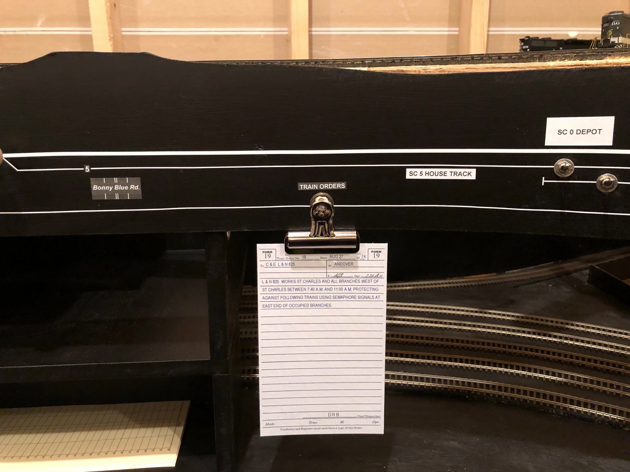
The scheduled trains on the St Charles Branch are “out and backs” which means they have a single crew and set of locomotives, but they’re technically two trains, one in each direction. This means most crews will have at least two train orders. The L&N crews receive clearance from the L&N dispatcher initially and run according to timetable on the Southern as far as St Charles. From there, they need to pick up a Southern train order to proceed railroad-west past St Charles and work the branches. I’m currently using a clip on the fascia near where the St Charles depot will go with orders to be picked up, and I’ll eventually have a semaphore at the depot I can set to tell the crews to stop.
A train order awaiting pick-up at St Charles
So far I’ve got a way to keep the trains moving and separated without a dispatcher–time to move on to getting the cars to the right locations.
Part 2. Moving the Cars
There are many ways to move cars on a model railroad including tabs on cars, car cards with waybills, and switch lists. The benefit of tabs on cars is the tab (like a waybill tacked to the car) follows the car and doesn’t create a need to carry a lot of extra paper. It also doesn’t need unique car numbers, something important with model runs of single car numbers a couple decades ago. However, for me, tabs on cars is not an option because I don’t want non-prototypical things cluttering up my models and breaking the illusion of reality more than the models are already doing, and all my cars will have unique numbers anyway. Car cards with waybills do a great job of moving a car’s destination from location to location using the prototypical practice of a “waybill” and providing additional details about a car’s lading. On the downside, they require some training (like when to flip a waybill), they require extra space on the layout/fascia at each town, and they require operators to carry a bunch of cards along with their train–I’ve been at operating sessions where cards went flying, went missing, or got separated from their car leading to messes, “mystery cars” and operator confusion. Additionally, the movement cycles of a coal hopper are very simple, and the lading and load/empty status are self-evident taking away two benefits of car cards.
Switch Lists
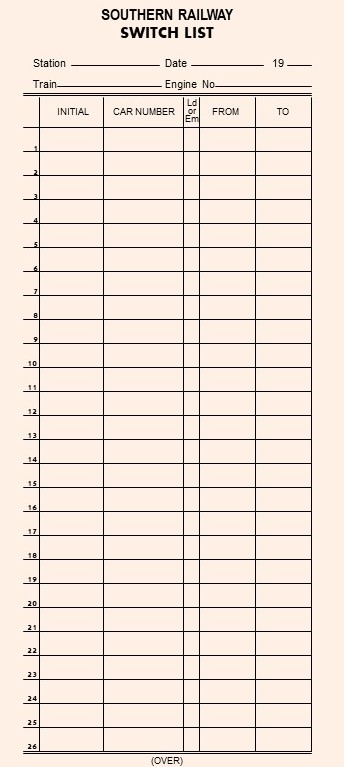
Recreated Southern switch list for my layout
That left me with switch lists. Switch lists are used on the prototype, either hand written or computer generated. They’re used mainly on local trains that will be setting off and picking up cars (not really needed for a train that’s not doing any switching). The switch list is specific to a train and tells the crew where each car in their train needs to go using the car’s initials (e.g., “SOU” and “LN”), car number, and some sort of destination designator. They often have additional information such as the car’s tonnage and load/empty status. The switch list is built by the conductor FROM any waybills or other routing information the conductor may have, so a crew doesn’t really need the individual waybills if they have a switch list.
On my last layout, I created a master list of every car on the layout and its destination (call it a “master switch list”), and I provided crews with blank switch lists they could use to build a tailored list for their train, much like a real conductor would do. However, I soon found that only the most die hard members of the crew would take the time to build their own list. For now, I’m building the switch lists for my crews and making it part of their starting paperwork along with the timetable and train order. I use the front side of the switch list for the outbound cars and the backside of the switch list for inbound cars, so crews merely have to flip it over instead of building it. I may revert to having crews build their own (or at least portions of it) in the future, but for now, I view the USE of a switch list as essential paperwork but the BUILDING of a switch list as tedium which I’m willing to endure but not push onto my operators.
To create the switch lists, I built forms in my favorite graphics program (yup, Microsoft PowerPoint) that I print out 3-per-page, front-and-back on thick tan paper and cut out. I found pictures of both Southern and L&N switch lists online (eBay is a great source for pics of old documents like this) and created railroad-specific switch lists for crews (L&N version below).
Destination Codes
A key part of a switch list (and a waybill) is understanding the destination of the car. This can be done in many ways as long as each destination is unambiguous. Because a train usually performs switching within a town/station area, trains are typically “blocked” to group cars for each town/station–this makes it very helpful to include the town/station in the destination for each car. Once the car gets put on the correct train and taken to the correct town, it needs some sort of unique industry identifier, and for industries with more than one track, a unique track identifier. While you can use long-hand like “Mayflower / Mayflower Tipple / Empty track #3” as a destination, it gets a little tedious to write out, so like many other modelers, I use short-hand 2-letter codes for each town and a unique number for every track in the town. Here are my town codes for on-layout destinations:
SC – St Charles
BK – Baker
MY – Mayflower
TS – Turners Siding
KG – Kemmergem
MO – Monarch
BE – Benedict
I picked letters that not only make sense for the town name but are also hard to confuse with anything. For example, both “Mayflower” and “Monarch” codes start with an “M,” so I chose a second letter that would be hard to confuse with the other name (i.e., “Y” is found only in Mayflower and “O” only makes sense for Monarch).
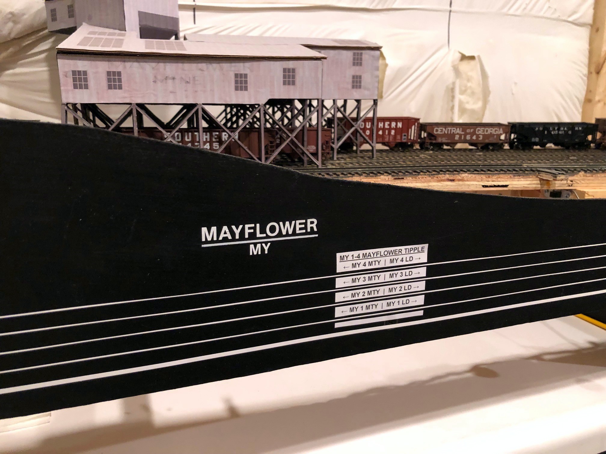
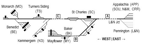
Track diagram and destination markings on the fascia at Mayflower
For the second part of the designator, I could have gone with a second letter/number for the industry and a third designator for the individual track within the industry. Instead, I opted to only use track designators since it still gets the job done and cuts out an extra symbol. So, for a town that had two industries with 3 tracks each, one industry would have tracks 1-3 and another industry would have tracks 4-6. For tracks with multiple industries on a single track, I use “4B,” “4C” etc. for each destination. For example, at the Mayflower tipple, I have a place to spot boxcars or flatcars bringing in material on part of tipple track 4, so this destination gets it’s own “4B” designator to differentiate it from the tipple. Tipple tracks on the prototype inherently have separate areas for “empties” and “loads”–because an operator can easily see if a hopper/gondola is empty or loaded, I didn’t include this in the destination code. I also created a unique track designator for ALL tracks that could be a destination for a car and not just fixed industries–for example, I sometimes use the end of the main at Mayflower as a place to spot a covered hopper, so I’ve designated the last 12 inches of the main as “track 5.” When looking at a switch list, each car bound for a destination on the layout will have a short-hand 3-letter destination code like “MY3”, or in the case of a track serving multiple spotting locations, “MY4B.”
I don’t expect operators to memorize these track numbers, so I place them on a track diagram on the layout fascia. Each town is clearly marked with its name and its 2-letter destination code. Each track is labeled near the turnout throw with its unique number. Each industry or destination spot is marked by a block at the intended spotting location containing its name and the associated track designator(s). In this way, an operator can arrive at a town, look at the fascia, and by checking the switch list know where each car in the train should go.
Track Chart
Most railroads also publish track charts for all their lines. The track chart contains useful information like grades and curvature, but it also includes a block diagram for each section of track with the town name and a diagram of all the tracks and their length–this diagram is often drawn in a blocky style using only 0, 45 and 90-degree lines. While crews on my layout don’t necessarily need to know grades and curvature, they do need to have a basic understanding of where towns are in relation to one another. For this, I drew up a simple little track chart of the entire layout for operators to use.
Simple track chart for my St Charles Branch layout
The track chart is laid out in “right = east” orientation and includes the town names (and short-hand designation) in the correct order. It also has a basic track diagram of each town, and I’ve depicted tipple and depot locations (depots are usually drawn on track charts, tipples are usually not). I’ve also included dashed lines for the hidden areas of the layout with letters that correspond to markings on the fascia to help crews better understand logically where their train is headed when they head out of the visible scene. The track diagram also helps them understand how to construct and block their train when heading west of St. Charles.
Blocking Instructions
Southern Blocking Instructions for layout crews
Speaking of blocking a train, prototype trains aren’t put together in random order but rather are assembled into “blocks” based on the destinations of the cars. Switching and local crews are typically required to block their trains in a certain manner to make them easier to handle at the next station or by the receiving crew, so I want to simulate this on the layout as well. Trains waiting in staging are already blocked by me before an operating session (you’re welcome), so the majority of the blocking for crews is for trains taking cars from the upper layout to staging. I could have just left the blocking at “Southern” and “L&N,” but I wanted to give crews a little more prototypical work to do. In addition to the online destination codes, I’ve got multiple destination codes for the Southern’s offline staging yard representing Appalachia, VA (pre-1965) or Andover, VA (post-1965). The loaders in the vicinity of St Charles loaded mainly two types of coal: raw coal for the huge Westmoreland transloader in Appalachia and clean coal bound directly for customers (routed geographically south of Appalachia/Andover) or to connections east of Appalachia/Andover with the N&W and Clinchfield, so all cars that aren’t L&N have a destination code APP, SOU, N&W or CRR to be used by crews to block their trains prior to returning to staging.
The Southern produced a periodic document called Freight Train Schedules and Blocking Instructions. This book has a page for every scheduled freight on the railroad describing how it should be blocked including engines, cars by destination, and caboose. I’ve created a similar document for my crews. In addition to blocking by destination, I’ve also included blocking instructions that place loaded cars on the head end of empty hopper trains and empty cars on the back end of loaded hopper trains, a common prototype practice to improve train handling on grades and curves. I also add a couple basic instructions for the crew to help them understand the train’s purpose and their chores a little better.
Part 3. Putting It All Together
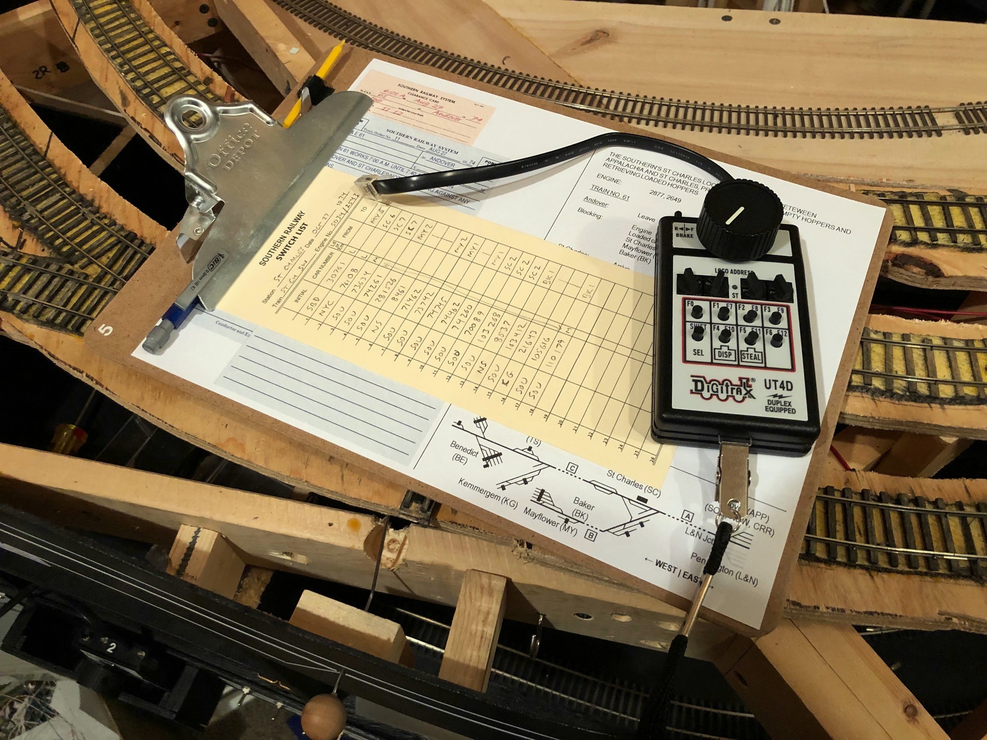
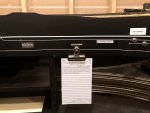
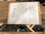
So, in summary, a crew on the St Charles Branch needs a timetable for basic train schedules and area instructions, a clearance card telling them how many train orders they have, at least one train order giving them clearance and specific instructions for their job that day, a switch list telling them where each car should go, a key for each town labeling destination tracks to match the switch list, blocking instructions to get cars ready for the return trip off the layout, and a track chart to help their brains understand the arrangement of towns and tracks. That sounds like a lot of paperwork, but it really isn’t. First, the “key” for each town is on the layout fascia, so they don’t have to carry it with them. Most of the other bits of paper can be combined into a single sheet. For each train, I build a single sheet that has the clearance card and train orders printed on the left, the train description and blocking instructions on the upper right, and the track chart in the lower right. Now, when you add the timetable and switch list, the operator only needs 3 physical sheets of paper. This is still a bit much to carry loose, so I provide each crew with a clipboard for their train. Clipped on the front is the sheet with clearance card/train order/blocking instructions/track chart. On top of that is the switch list. The timetable goes into a plastic sheet protector on the back for easy reference. Add a pencil and an uncoupling tool (attached by Velcro), hand them a throttle, and they’ve got everything needed to operate successfully on the railroad!
Single sheet for crews with clearance card, train order, blocking instructions, and track chartThe one-page timetable fits neatly in a plastic pocket on the back of a clipboard
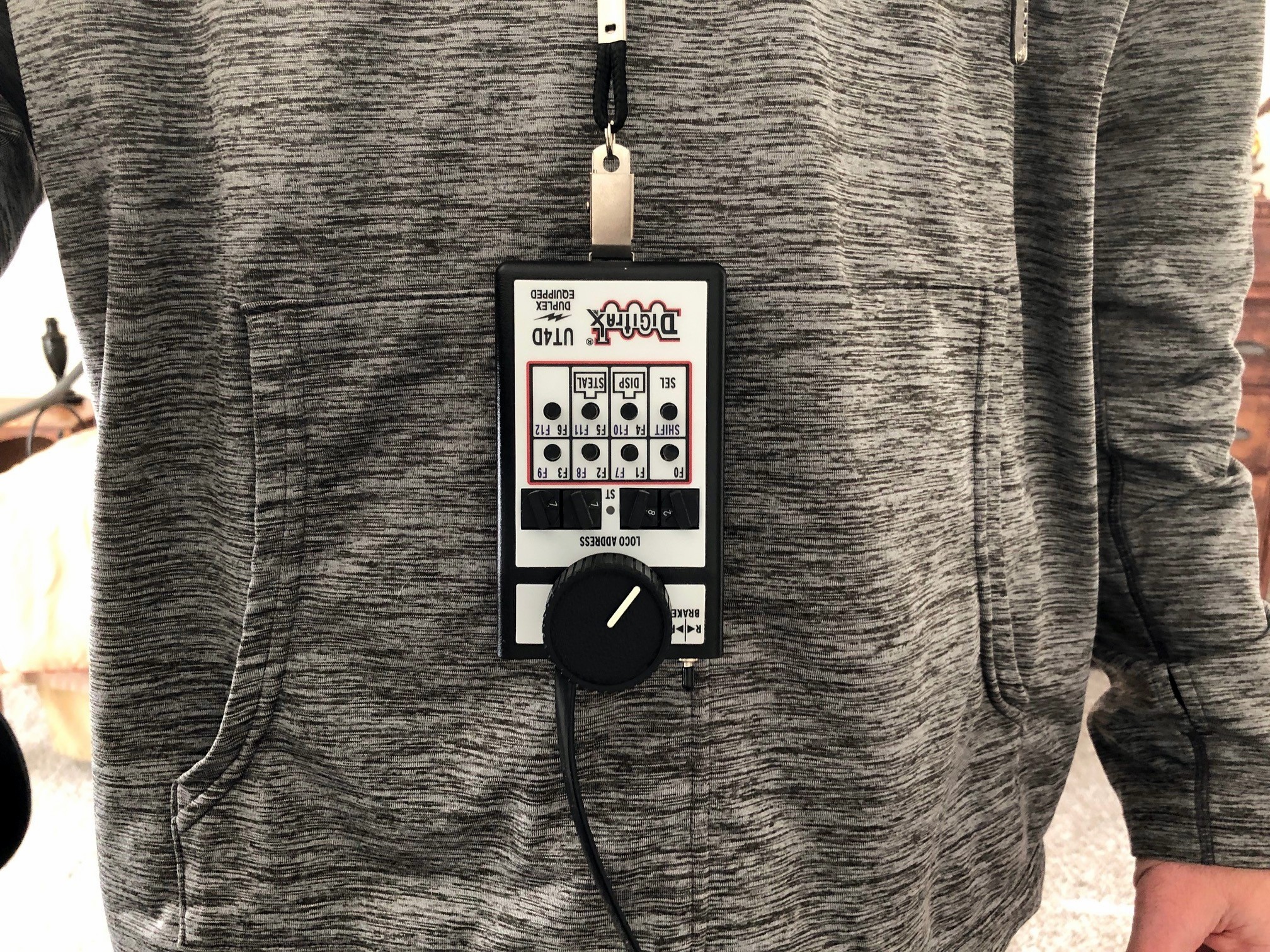
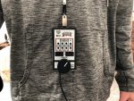
One final note, when using model paperwork, operators need a convenient place to set things down or else they’ll either leave it behind (bad) or set it on top of the layout (more bad). For those who’ve been keeping up with the layout’s progress, you’ll remember the fascia pockets I build around the layout between the staging and lower levels–this is why they exist. No matter where an operator is in the layout room, they’re never more than about an arm’s length away from a clipboard pocket. How about the throttles? When an operator is handling a train solo, they need to be able to quickly set the throttle down to interact with the paperwork. While there are throttle pockets all around the layout, it’s even better if the operator can just keep the throttle with them. This is where the throttle lanyards that allow an operator to just drop the throttle and let it dangle from their neck come in real handy–this is perhaps the best $1.50 solution to a $25.00 problem on the layout so far!
Conclusion
I’ve taken a little more time on this post because I want it to serve as a more thorough article for those looking for ideas on realistic model railroad operations. I will never claim to have “THE solution,” and there are definitely pluses and minuses to my methods. I do believe this method, though, strikes a good balance that gives the die hard prototype enthusiast or ex-railroader enough sufficiently realistic paperwork to make them feel at home while being limited and simple enough to avoid intimidating newbies or weighing crews down with tedious tasks that only a small percentage of people find fun. While I will continue to refine my operations as the layout evolves, this method definitely meets my goals and needs for the short-term. I’m always learning, so please feel free to post your critiques, feedback and better ideas in the comments section! I’ve also included some jpegs of the blank forms below–feel free to use these for your own personal use. The easiest way to “fill them out” is to copy the images into MS PowerPoint or similar program and create a text box on top of the image.
Clearance card showing how many orders the crew has
An example of my model Southern Form 19 train order
An example of my model L&N Form 31 train order
Southern Blocking Instructions for layout crews
Single sheet for crews with clearance card, train order, blocking instructions, and track chart
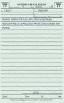
My blank Clearance Card
My blank Southern Form 19
My blank L&N Form 31
A train order awaiting pick-up at St Charles
Everything the St Charles Local needs to operate on the layout
The one-page timetable fits neatly in a plastic pocket on the back of a clipboard
I’m continuing to capture little projects on the layout as I think about them. I bought a “spare” Digitrax UT4D utility throttle recently and was reminded of the modification I’ve done to all my UT4s to make them more user friendly. I use the UT4D 2-way radio throttles because they’re light, very easy to use, and the wireless makes them very convenient to use anywhere on the layout. Despite this convenience, there’s still one major problem with the UT4 (or any walk-around throttle for that matter)–where do you set it when you’re not using it? This is not a problem when you’re done with your train as I’ve got plenty of throttle pockets along the fascia in which to stash them and plug them in to keep the batteries from draining. But what do you do with the throttle when you need your hands for other chores like uncoupling and paperwork? This is a major consideration for a switching oriented layout like the St Charles Branch.
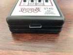
On my last layout, I came up with the idea of attaching a simple anchor for a clip-style lanyard. It does require drilling a couple holes into your throttle, but it’s only through a narrow part of the plastic casing and into the battery compartment, so it’s not a threat to the throttle’s electronics. The anchor is made from .025″ steel music wire which you can pick up at most hobby stores. Lanyards come in many styles, but I use the lanyards with the “bulldog clip” that doesn’t swivel and provides a very easy pinch mechanism to attach and release the throttle such as the ones in this link (yes, I get a little commission if you use this link, and it doesn’t cost you anything extra to use this link–thank you).
Here are the rest of the steps:
REMOVE THE 9V BATTERY FROM THE UT4!!!
Cut a piece of .025″ steel wire about 2″ long
Bend into a squared-off “U” with the bottom about 1/2″ wide (just wide enough for the lanyard clip with about 1/32″ of slack) and each side about 3/4″ long
Mark the bottom of the UT4 throttle case for drill holes–make them the width of the U and centered within the “groove” of the plastic
Drill 2 holes into the case–use a drill bit that’s slightly oversized so the wire slides freely without rattling
Insert the wire “U” into the case and attach a lanyard to the bottom of the “U”
Push the “U” into the case as far as it will go and then back off just slightly (“U” extends approximately 1/8″ from bottom of throttle case)
Bend the ends of the “U” that are inside the case outward to mark where the bends need to be
Remove the lanyard, push the “U” as far as it will go into the case and bend the ends inside the case with needle-nosed pliers until they are parallel with the case bottom
Extend the “U” outside the case then reinsert 9V battery, pushing it up against the top (antenna side) of the throttle as far as it will go
You should now have a clip anchor that retracts into the little groove when the throttle is set down on top of it that extends just enough to allow a lanyard to attach when picked up. It doesn’t get in the way of anything if an operator chooses not to use a lanyard, and it provides a secure way to let the throttle dangle when not needed. I’ve been using these mechanisms for years and have never had a catastrophic throttle drop (your results may vary ;-). Similar techniques may work on other throttles as well, though I’ve only tried it on the UT4D.
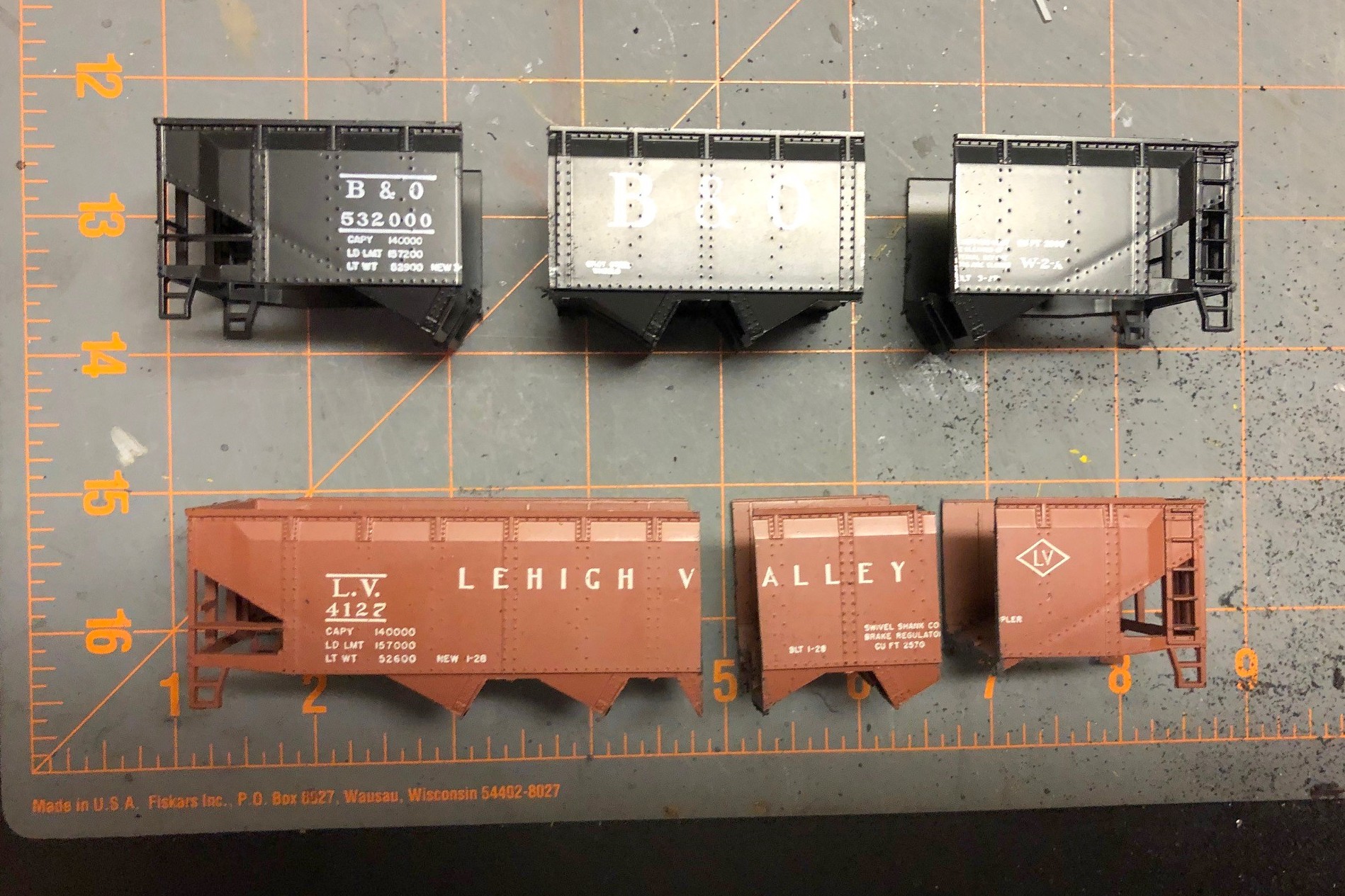
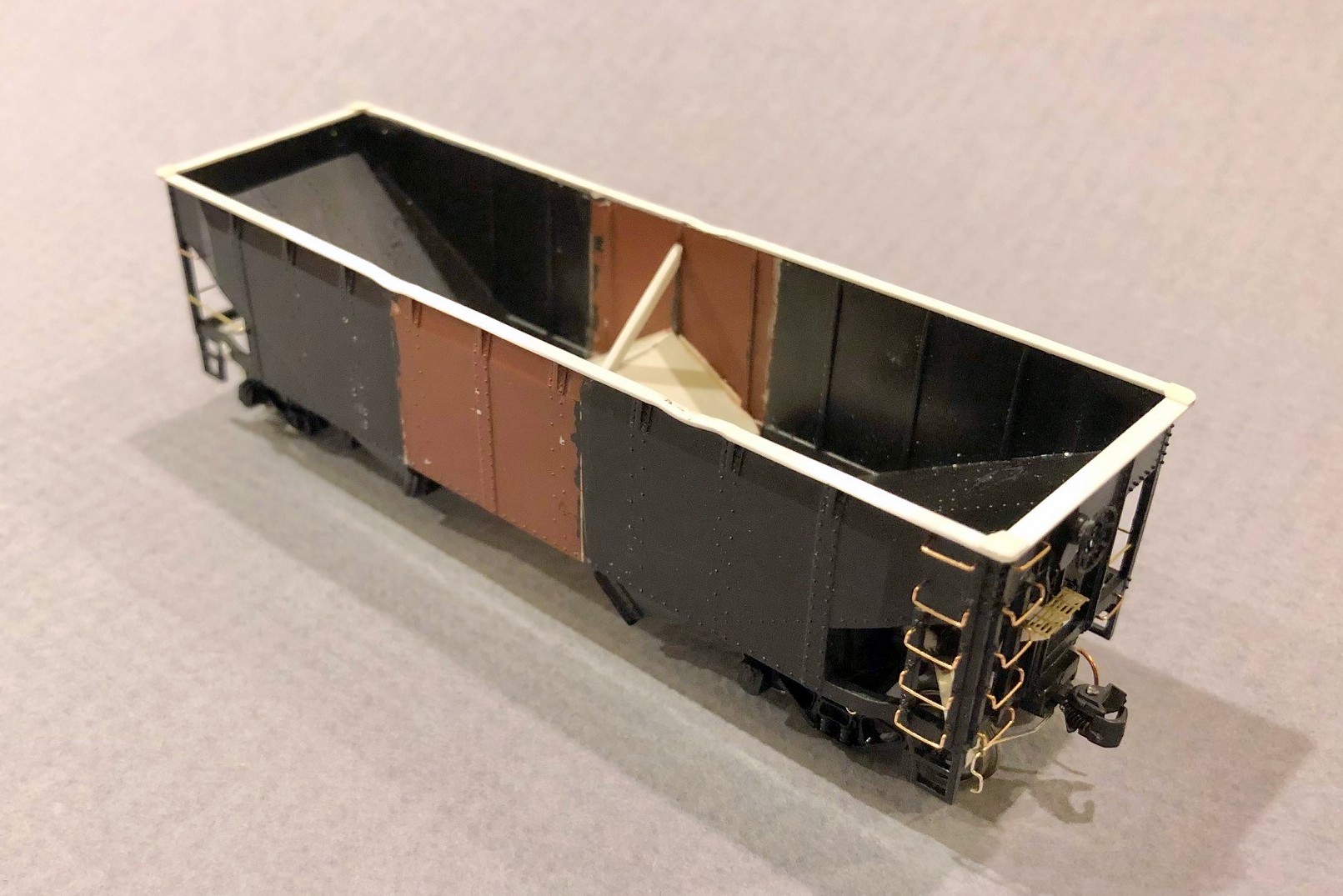
I’d had my eye on this project since the first time I saw a picture of one of these cars online. There were two challenges that held me back. First, no one made the right decals. Secondly, no one makes this car, so it would be a pretty major kitbash. It’ sat on the “someday” list until K4 Decals produced a set of good looking decals. The main excuse was now out-the-window, so I had to bite the bullet and figure out how to kitbash the car. The challenge is the shallower and steeper offset angles–they’re very distinctive and different from the angles on common twin hoppers like the old Athearn and newer Atlas models. The only thing that looked close were the angles on the old Athearn blue box quad hopper. I had one sitting on the shelf, so I took a closer look. It turns out the angles are perfect, as are the rivet strips and rivet patterns along the ribs. So, how to turn a quad hopper into a twin.
Cutting down a quad hopper to make a twin sounds pretty straightforward. If you don’t care about having an extra rivet strip, it is! Of course, I had to care… sigh. There’s an extra rib between the rivet strips on the twin compared to the quad, so I had to figure out how to get the extra rib in there. Turns out, there’s just no way to do it with a single shell (or I wasn’t smart enough to figure it out), but it was possible using two shells–2 quad shells to make a 1 twin… makes sense. I guess technically I could make 2 twins with 3 shells, so I did keep the extra pieces in case the bug strikes again.
2. Cut hopper bodies
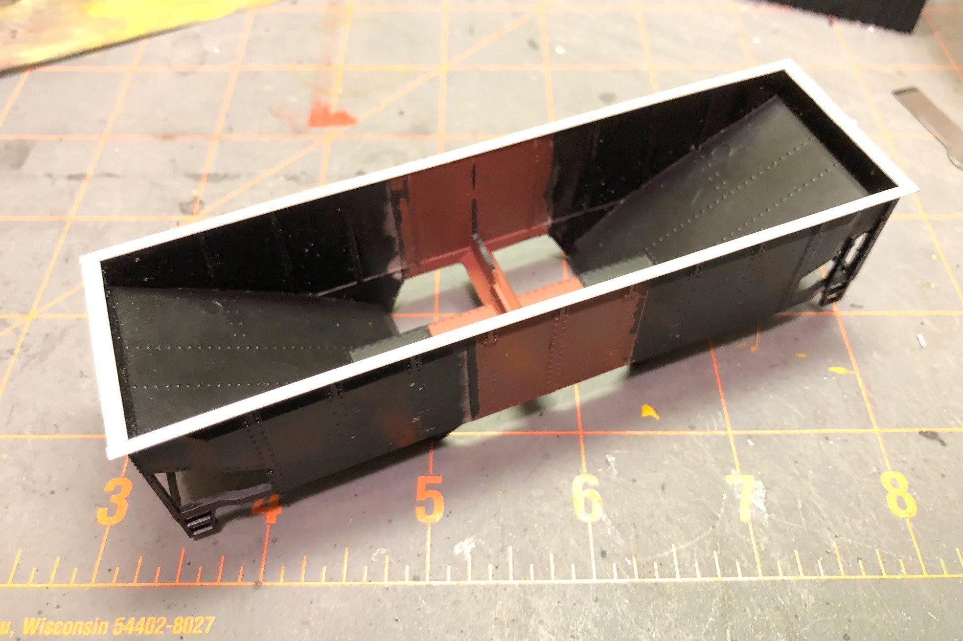
Picture 1 in the gallery shows the two original shells, and you can make out the pencil lines where the cuts need to be. I chose a spot between rivets to give myself a chance of saving the rivet detail in the putty and sanding step later. Using a razor saw, I cut each shell into three pieces as seen in picture 2 with the black hopper providing the ends and the red hopper providing the center. After cleaning the bays off what would become the center, I glued the ends to the new center piece as shown in picture 3. This step is the most critical of the whole project, and it took some filing to get everything square. I used plastic model cement to give myself time to line up the pieces–it’s crucial to get the sides aligned so they’re “level” across the gap. A gap is easy to fill and sand flat, but only if the sides are even with one another.
Once this new shell had dried thoroughly, I removed the top chord. The top chord on the original model is pretty chunky, and it would be easier to add a new one across the gap than try to fill every gap on top perfectly. It was pretty simple using a No 11 X-Acto blade swiped repeatedly under the top chord resulting in the shell seen in picture 4. Next, I filled the gaps with modeler’s putty. Using a combination of the back of an X-Acto blade and fine sandpaper, I was able to get the joint pretty smooth, and I was careful to stay away from the rivets as you can see in picture 5. This was also a good time to remove all the molded-on grabs with a combination of nippers and X-Acto blades. I found the corner posts and ladder posts to be really thick, so I whittled them down a little on the back side with an X-Acto. I also trimmed the top of the bottom sill near the ends to make it a consistent thickness instead of a taper like the model.
7. New styrene top chord
Next I worked on the center sill and undersides. First I cut the center out of a single underbody to shorten it to the right length and joined the ends together with glue. After it set, I used a large X-Acto chisel blade to remove some the material as shown in picture 6. I left a little strip to hold the hopper doors on. Next, I added a new top chord to the shell. I didn’t have the bag to verify, but I believe I used Evergreen HO scale 2×6 for the sides and 2×8 for the end to get to picture 7. I added four corner caps made from .010″ sheet styrene and rounded them on the top and on the corner after they dried using a file. Moving back to the underbody, I removed the existing mounting “blobs” for the brake gear, and in their place, I added angles from the bolster area to the corners using strip styrene (this was a pain, but I found if I cut them to the approximate shape, glued them with plastic cement, then press fit the underbody onto the shell and maneuvered the angles into position while the glue was still wet (I didn’t glue the underbody to the shell yet). When the angles had set, I added the brake parts including some brass wire for piping and a bracket for the reservoir made from sheet styrene as shown in picture 8.
10. Finished interior
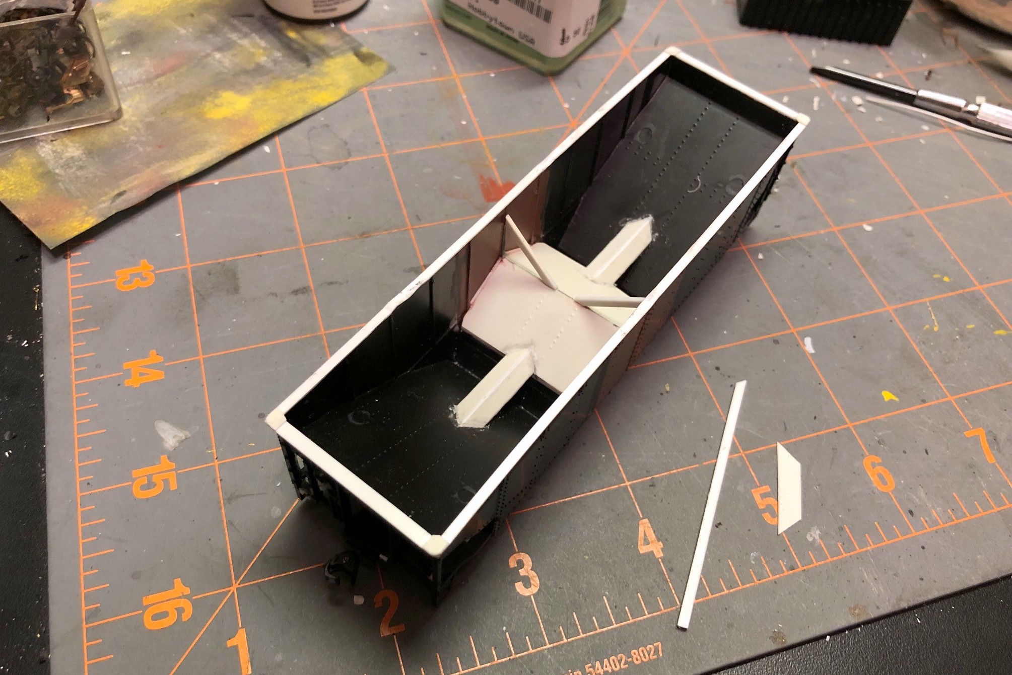
The interior of the car was challenging. I went ahead and glued the underbody and doors in place first, then added some styrene square rod above the doors to get it even with the model’s center sill piece. The new center slope sheets were cut from a single piece of styrene, and I used a pounce wheel to put some rivet lines into it to match the end slope sheets. Because of the ribs, the new slope sheet didn’t quite reach the sides, so I used bits of styrene to fill in the gap between ribs as seen in picture 9. Next came the not-so-fun part of turning the flat center sill ridge inside the car into a tapered one. I don’t have interior photos of one of these cars, but I can’t imagine using a flat top when you want the coal to exit the car. This step was not fun. Not one bit. Lot’s of measuring, cutting, folding, and taking back out and cutting again. My pieces ended up being too wide, but I just glued them on, let them set, then trimmed them to the width of the ridge in the shell with an X-Acto blade. Some styrene strips to make the angle braces and the interior was complete as seen in picture 10.
11. Final details added
Now I was ready for all the little details that you can see in picture 11. I drilled holes and installed all the grabs, making the long grabs on the non-ladder side from brass wire. I added coupler cut bars to a bracket made from styrene and an eye bolt. I made tow loops from brass wire, and I made a new brake platform from bits of styrene and some brass Apex roof walk material. I added the brake line along one side using brass wire and eye bolts. I added some tack boards from styrene on the bottom sill. I added train line hoses made from copper wire from old Cat 5 cable glued between two styrene angle bits (makes for an indestructible train line). A kept the molded on steps as I needed them to be durable for layout handling, but I used an X-Acto blade to shave them down a bit in the back to thin them out. Finally, I added a little buckling to the top chord using a 100W lightbulb held to the styrene for a few seconds and then pushed down using the handle of an X-Acto knife (be careful, the styrene melts really quickly). It was finally ready for paint (picture 12).
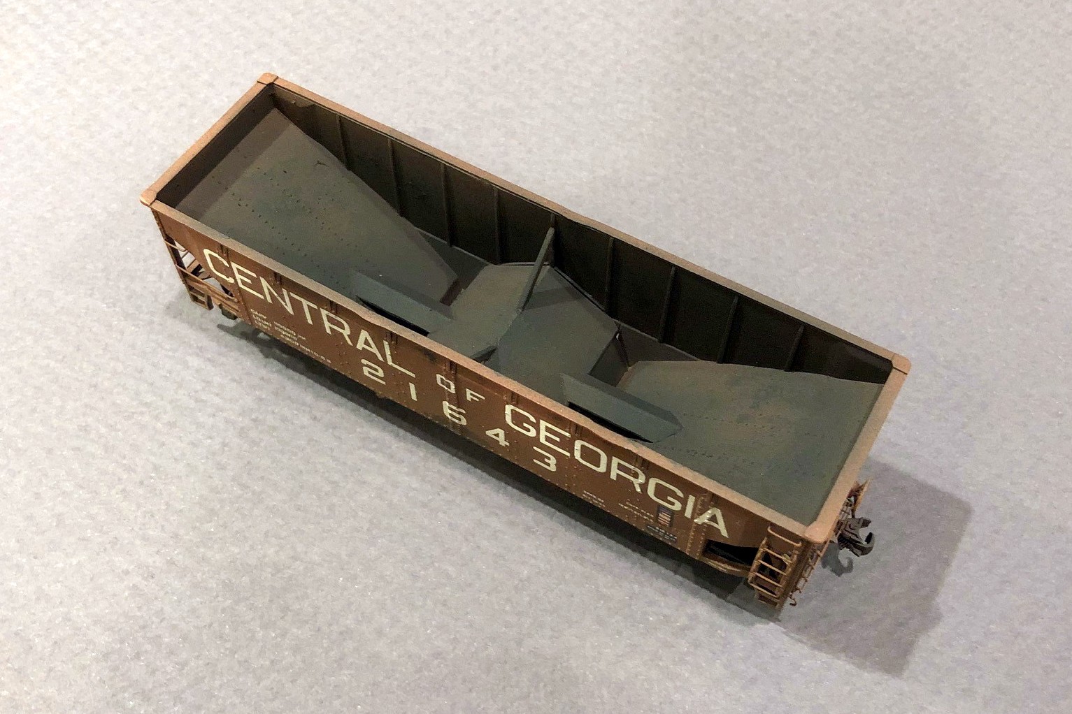
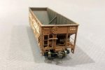
16. Final hopper – interior weathering
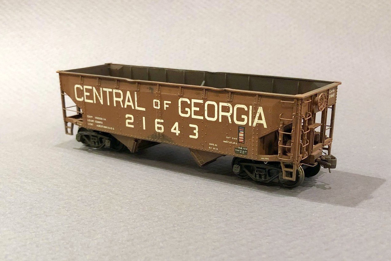
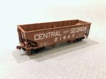
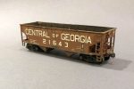
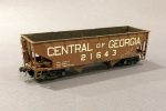
I first sprayed everything black, then gave it a couple coats of “burnt sienna” for the boxcar red. Because the paint was very flat, I sprayed it with a couple coats of Testors Glosscoat (rattle can) to prep it for decals. The K4 decals worked really well and had just about everything needed with the exception of an ACI label I stole from a Microscale data set. The K4 set looks like it’s designed for a 33′ car, and this prototype is a 34′ car. I ended up cutting the road name into “CENTRAL,” “OF” and “GEORGIA.” I place the end lettering first and then centered the “OF” between them, a little more spaced out than the decal sheet. I used about 800 applications of Micro Sol and Micro Set and pushed the decal firmly onto the body using a damp paper towel until everything was nice and snug over the rivets and on the body as seen in picture 13.
Weathering was a three step process. First, I dry brushed a little dark rust color both inside the hopper and in a few spots on the outside using a picture of this specific car as a guide. Next I gave it a couple of washes with very thinned black and then tan paint, wiping it off down the car (like rain streaks). Finally, I airbrushed some black inside the hopper and underneath followed by a couple coats of tan, hitting the trucks and hopper bays harder than the body to get the final model shown in pictures 14-17.
I’m very happy with how this project turned out, but I’m also very happy I don’t need a fleet of these cars. Many will look at this car on the layout as “just another offset hopper,” but I’ll always know the extra work that went into building a more accurate model of a neat prototype.
1. The two Athearn quad shells with pencil lines where the cuts will be made
Finished car with some light black and tan airbrushing on the sides, trucks and interior
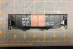
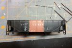
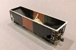
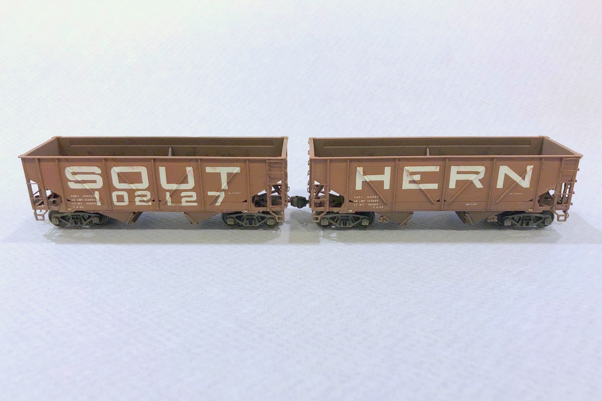
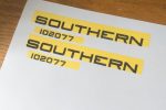
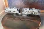
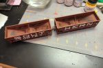
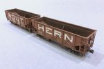
The Southern Railway was definitely known for innovation, especially in the ’60s. They were one of the first railroads to use large numbers of 100T hoppers for moving coal. The Southern still had a large number of usable 50T cars, particularly war emergency rebuilds and ex-Interstate hoppers, so they permanently paired some of them into what they deemed 100T “articulated hoppers.” There was nothing fancy about it, they just removed the coupler cut levers from between the cars, put the brake ends of each car at the ends, and numbered them as a single car. The idea was it allowed 100 tons of coal to be moved in a single car shipment for a customer which gave these old cars a little more life in the 100T era. There were several paint schemes used on these cars include a red version with “SOUTHERN” on the left-hand car and the car number on the right-hand car. Some cars had a black version of this. The most striking and unique cars were those painted with giant lettering and “SOUT” on one car and “HERN” on the other–this is the car I wanted to model.
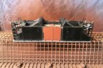
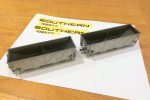
The base cars were easy enough. They’re essentially stock Proto 2000 War Emergency hoppers with a couple minor modifications. I trimmed the tow loops off the bottom, added small beveled strips of styrene under the outermost ribs, and used bent .012″ wire to fashion new side-mounted tow loops above the styrene strips. I also used dummy couplers on the “A” ends of the cars that I pulled out of an Accurail 50T AAR hopper kit–this will keep operators from inadvertently uncoupling the car on the layout. I only added coupler cut bars to the “B” ends like the prototype, and I added a scratchbuilt train line air hose to each end (piece of bent copper wire from old Cat 5 cable sandwiched between two styrene L-shapes).
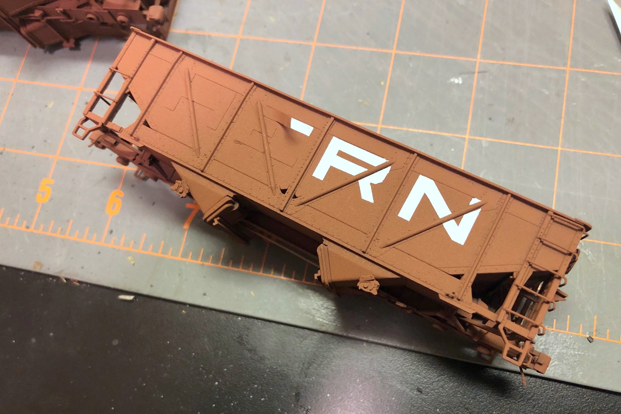
Step 4. Apply the lettering masks to the car, cutting around the ribs
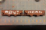
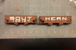
The tricky part of this model is the lettering. No one makes a lettering set that even comes close, so I would need to either make my own decals or somehow mask and paint the lettering–I opted for the latter technique. First, I had to draw up some artwork. I used my favorite graphics program, Microsoft PowerPoint, to create the lettering using large rectangles and quarter circles. Once it looked about right, I copied and pasted the lettering as an image (right click and picture icon) on a new sheet, then I was able to size it and print it with the letters 3′ tall in HO scale and the numbers 2′ tall. Then I covered the lettering with some Tamiya model masking tape and ran it through the printer again to get the ink onto the top of the tape. Warning: even after the ink dries, it still smears a bit, so I used another piece of plain masking tape to remove some of the ink, and I was careful not to get smudgy fingers on the car.
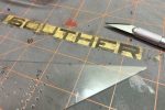
Speaking of the car, I airbrushed the sides white and let them dry overnight. Back to the lettering, I carefully peeled the tape off the paper and placed it on a clean cutting mat. Then I used a straightedge and Xacto blade to cut along all the straight edges. I freehanded the corners which was a bit more challenging. The angled ribs on this car required me to eyeball where the rib would go through the letter (I had a picture of an actual car), so for each rib I removed about 1/16″ of masking tape. Next, I peeled the letter mask off the cutting board and applied it lightly to the car, using a blade to lift and reposition it as needed. After all the lettering was in place, I used the round end of the Xacto handle to burnish the tape onto the sides securely.
Step 7. Carefully remove the masking using a sharp blade to get under the tape
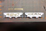
Back to the painting booth, I first sprayed the cars with black as a dark primer and then gave them a couple coats of oxide red and let them dry for an hour. After the paint was dry, I carefully removed the tape from the sides using a blade and careful fingers to reveal the white lettering. I thought I was going to have a lot of touch-up to do, but the tape held up very well and left mostly clean edges. With all the tape off, I then used a brush and white paint to fill in the lettering gaps across the ribs. I sprayed it with some gloss coat and applied the capacity stencils and other small lettering from a Microscale data sheet using multiple liberal coats of decal solvent and decal setting solution. After letting the decals dry for a day, I hit the cars with another coat of gloss (the paint came out REALLY dull, so even with three coats of gloss it’s pretty dull).
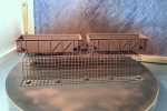
For weathering, I first dry brushed a little light rust and dark rust onto the car, mostly on the inside to simulate a few years of wear with the paint just starting to wear through where the coal repeatedly tugs at it. Next I gave all surfaces of the car a couple coats of black wash (water with a dab of paint). I worked one set of sides at a time (one “SOUT” and one “HERN”) to ensure the weathering was consistent across cars, brushing on the wash, letting it sit for a couple minutes, then dabbing and streaking it off down the sides with a moist paper towel. I followed the black wash with a single wash of tan. The final weathering was some black airbrushing inside the hopper and along the bottom followed by some light tan airbrushing on the sides and trucks.
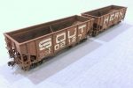
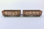
Finished 100T articulated hopper showing the huge “SOUT” and “HERN” lettering
I’m pretty happy with how this car turned out. It’s definitely unique and is bound to be a conversation piece on the layout. I can’t wait to watch the first operator trying to uncouple the dummy couplers so I can give them a little history lesson in Southern innovation!
Step 1. Print the artwork, cover with masking tape, and print again
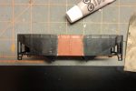
Step 2. Paint the sides of the cars white
Step 3. Cut out the letters using a sharp blade and straightedge
Step 4. Apply the lettering masks to the car, cutting around the ribs
Step 5. Paint the car (I primed with black first)
Step 6. Let the paint dry
Step 7. Carefully remove the masking using a sharp blade to get under the tape
Step 8. Ensure all tape is removed
Step 9. Paint the white lettering onto the ribs using a brush
Step 10. Dry brush some rust–I dry brushed lightly on the sides and a little heavier inside, then I did a black wash and a tan wash
Step 11. Finished car with some light black and tan airbrushing on the sides, trucks and interior
Finished car showing the brake detail on the ends
Finished 100T articulated hopper showing the huge “SOUT” and “HERN” lettering
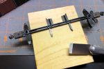
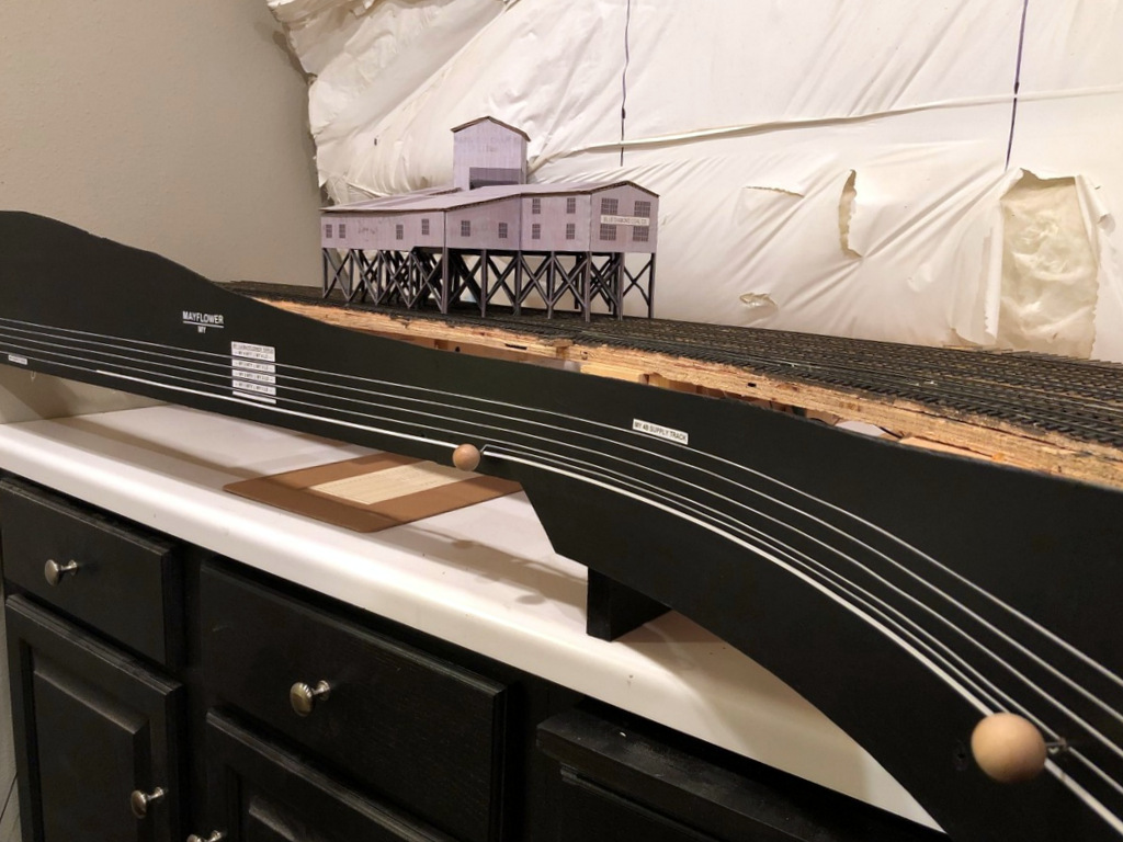
Finished fascia and labels at MayflowerI set a combination square to the right height and slide it along the bottom of the fascia while dragging a pencil across the top to draw straight lines for the track diagram
Working on the fascia is very mundane and unexciting, but as a human factors engineer by education, I take my fascia very seriously! On most layouts, the fascia is the primary interface between operators and the layout. It’s often where we place controls and place names, and it’s also a blank canvas we can use to help our operators better understand the scene they’re interacting with. Like many who perform switching operations on their layouts, I like to use the fascia to help operators understand as much as possible about towns, tracks and industries to aid in making their switching moves.
As far as construction goes, my fascia is just sheet Masonite fastened to the benchwork with drywall screws. I cut it in thick strips that will account for all the vertical scenery contours along the front edge. Where there are noticeable gaps or indentations from the screws, I touch things up with lightweight spackling compound and wipe it smooth with a damp cloth after letting it harden for about an hour–this saves a lot of time sanding later. Then I draw in the ground contour with a pencil and cut it with a jigsaw. A little black paint, and things are ready for the operator features.
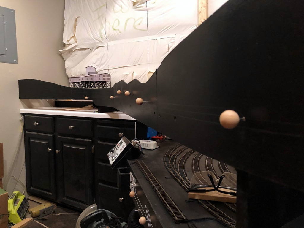
All the Mayflower switch controls installed–they’re at different elevations to line up with the track diagram that will be installed on the fascia
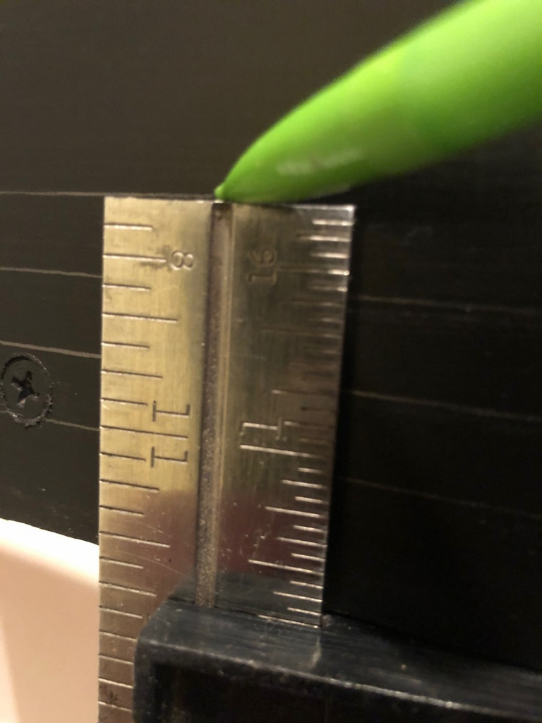
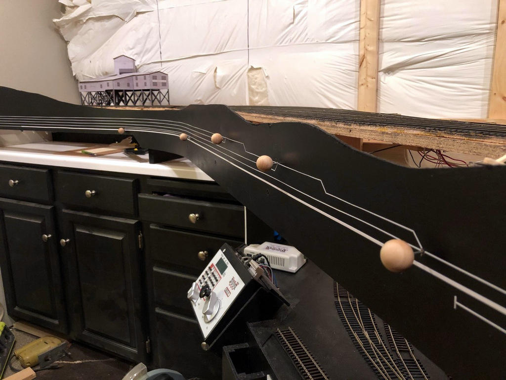
On my last layout, I drew the track diagram onto the front of the fascia, and it worked so well I decided to continue it on my new layout. It’s essentially an elongated track diagram like you’d find in a railroad track chart that lines up with the adjacent track and switches on the layout. I draw the lines parallel to the bottom of the fascia 3/8″ apart. To draw them, I’ll set a combination square so the end of the ruler is at the exact height I want when the square is pressed against the bottom of the fascia, then I’ll run the combination square around the bottom of the fascia while dragging a pencil along the top to draw it onto the fascia. I draw the switches onto the fascia at 45 degree angles with the convergence drawn where I want the switch control rod to be placed (directly perpendicular to the switch mechanism usually). One lesson learned from my last layout I was able to incorporate into this one is that the “straight” line through a switch control is the “normal” position of the switch while the “divergent” line represents the “thrown” position. It required a little “wiggling” of the track lines in the yard ladder to make this work, but it’s intended to help operators understand how to set the switches before departing a town.
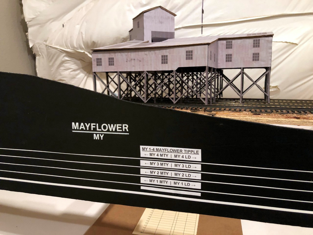
Finished fascia labels with the town name and siding identifiers for the Mayflower Tipple
I installed the switch control rods (see full article on switch control mechanisms here) after the lines were drawn but before placing the graphic tape on the fascia to represent the tracks. I use two sizes of white graphic tape for the tracks, 3/32″ to represent the main, and 1/32″ to represent sidings. This offers another visual clue for operators so they know which tracks not to block and what to leave clear after leaving town. Next come the labels. Every town on the layout has both a name and a unique 2-letter destination code for routing cars. In this case, Mayflower is represented by “MY.” Within each town, each track has a unique number, for example, MY 1 is the tipple track for the Mayflower Tipple closest to the main. For tipples, I also designate where the empty (MTY) and loaded (LD) cars go, so an empty hopper destined to be loaded on Mayflower’s outermost track would need to be placed at MY 4 MTY. Towns are labeled with large dry transfer lettering with the town name above a line and its destination code in smaller letters below. I also cut a small gap in each track tape on the fascia near the switch and use dry transfer numbers to label each track by number. Industries are given white labels with black lettering that gives the industry name, town initials, track number(s) and MTY | LD track dividing line if needed (see picture of the Mayflower Tipple and its labels). If two or more industries are on the same track, I use a “B,” “C” or so forth to denote each spotting location. In the case of Mayflower, I’ve identified a spot on load track 4 where I might have operators occasionally spot cars of supplies and a spot on the tail track of the main where I might have them spot covered hoppers of AN–each of these spots has its own industry label adjacent to the correct track on the fascia track diagram to make it clear where to spot the cars.
There’s nothing really novel here, but I do think this method of using track diagrams on the fascia and integrating switch controls, town names and industry track designators with unique operational codes goes a long way toward making the layout more intuitive and operator-friendly.
Roughed in masonite fascia awaiting sculpting
Here the fascia has been cut to shape, sanded, and painted
I set a combination square to the right height and slide it along the bottom of the fascia while dragging a pencil across the top to draw straight lines for the track diagram
All the Mayflower switch controls installed–they’re at different elevations to line up with the track diagram that will be installed on the fascia
Extra wood glued behind the fascia supports the switch throw rods and makes the fascia stronger
Nearly final fascia in Mayflower with the track diagram in place
Finished fascia and labels at Mayflower
Finished fascia labels with the town name and siding identifiers for the Mayflower Tipple
View of the finished load tracks from the top of the tipple–note the track that’s been removed on the left side (thought it would make a cool detail)
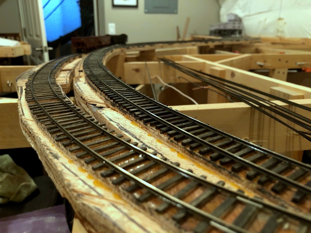
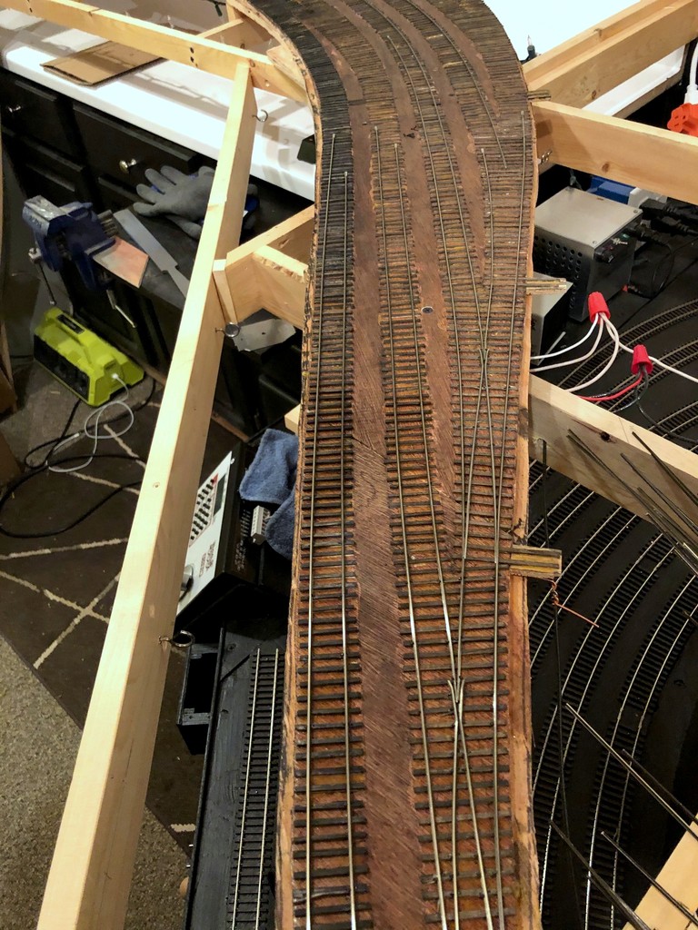
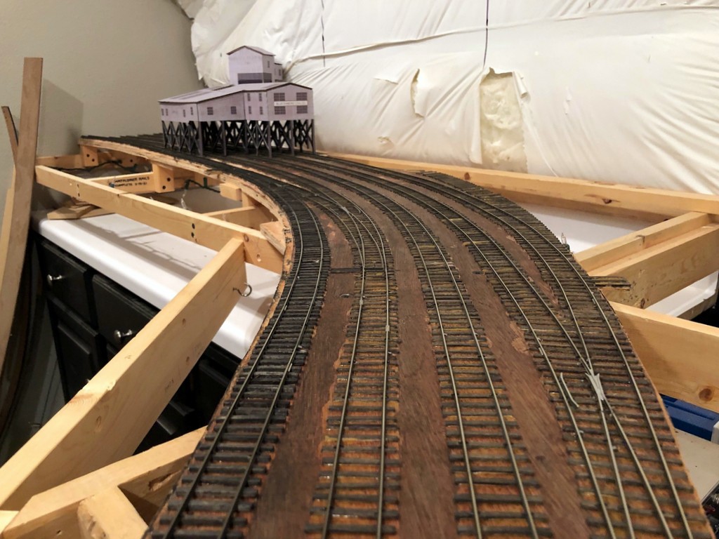
I’ve completed laying rails on the Mayflower section of the railroad, and I’m just about ready to run the first mine run–exciting times! Everything is hand-laid, and I’ll share a little about my technique. I lay everything in place instead of using a jig because I find the track flows better. I use code 83 for the main and code 70 for sidings, and I spike everything with small spikes, about every 5th tie except for switches. I like to work outside-in as you’ll see in the pictures of the load yard ladder. This means the first few switches take a while because you’re notching for the points of ALL the switches on that piece of rail, but it speeds up as you go because you’ve already filed pieces up-front. I don’t pay much attention to frog numbers or curves–I just lay them as the ties dictate (and remember, the ties were laid down based on outlines traced around flex track, so that’s where I check radii and things).
You also might notice that I’m not putting in guard rails alongside the frogs for some switches which is prototypical for sidings in some areas of the country. I use them on both sides of every mainline switch, and I use them on the tightest curve side of every curved switch. For the rest, I test cars and put them in as needed. If your frog is straight, you probably wont need them. If your frog is curved at all, you probably will. I like the look of the switches with no guard rails because it emphasizes “siding.” I also use the track to tell part of the story, so you’ll notice that I laid an extra switch’s worth of ties for a 5th track under the tipple that has been removed (try doing THAT with commercial track)–Mayflower had a spot to load on a 5th track, but track diagrams in my era only show 4 tracks. I’ve modeled it as if they just pulled up the rails and laid through the switch instead of pulling up all the ties.
All the feeders (a gazillion) got dropped and attached yesterday, so I just need to set out some cars and recruit my engineer for the first-ever mine run on the layout. Woohoo!
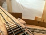
This is the siding for a small truck dump at Baker–I used cookie cutter benchwork to get some good elevation difference, and I laid the rails for the siding very sloppily from side-to-side to show kinks of a well-used and minimally maintained siding
Overview of the ladder in Mayflower with the first couple rails in–I work “outside-in”
A little further along showing some of the “inside” rails being laid
Nearly finished yard ladder. The point rails haven’t been bent yet to put inward tension on the throw bar (which will be inserted soon)
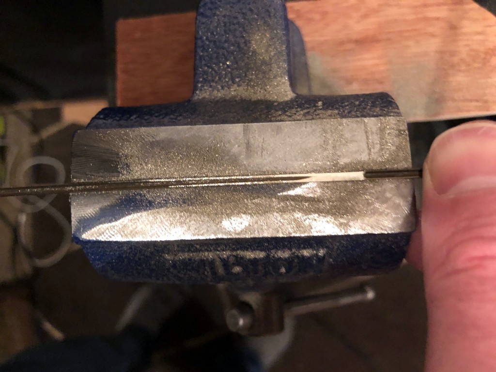
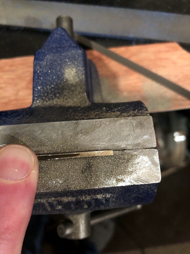
Filing one of the notches in the stock rail–I just use a triangle file and bench vise with the rail sitting in the seam
I file points with a triangle file on top of a small bench vise–the seam holds the rail in place well enough without clamping
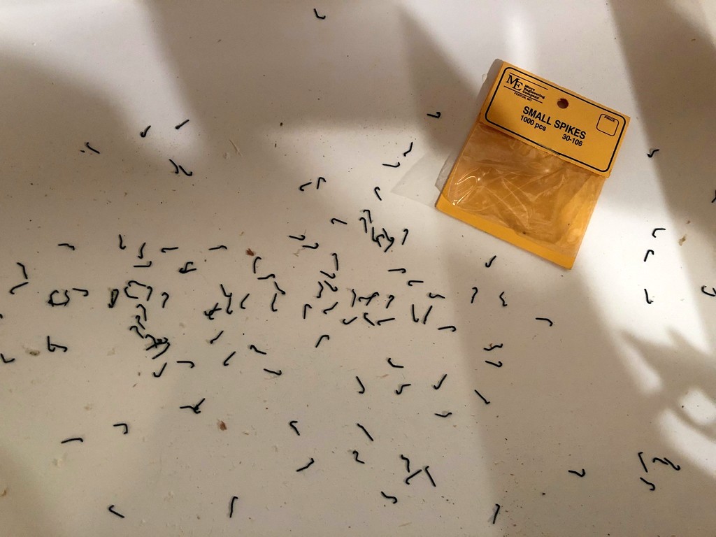
I’m not too impressed with the “new and improved” Micro Engineering small spikes–they bend a WHOLE lot easier than the original
Looking “north” at the finished tracks of the load yard at Mayflower with the tipple mock-up in the background
View of the finished load tracks from the top of the tipple–note the track that’s been removed on the left side (thought it would make a cool detail)
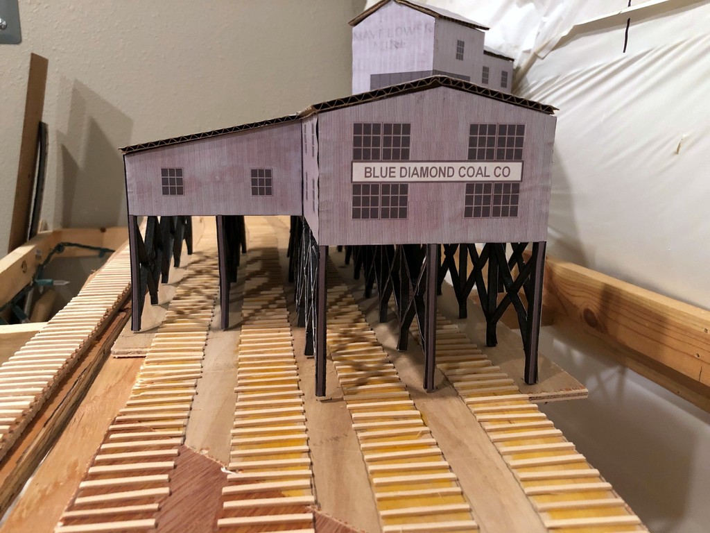
A close-up of the Mayflower Tipple mock-up with ties running underneath
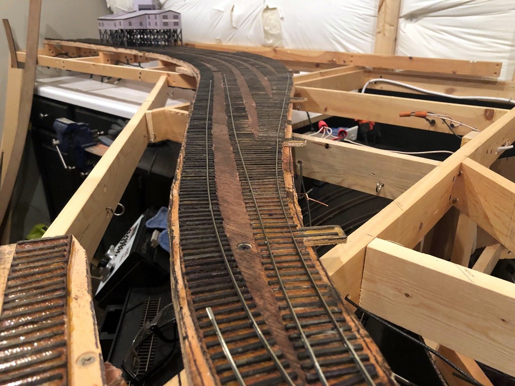
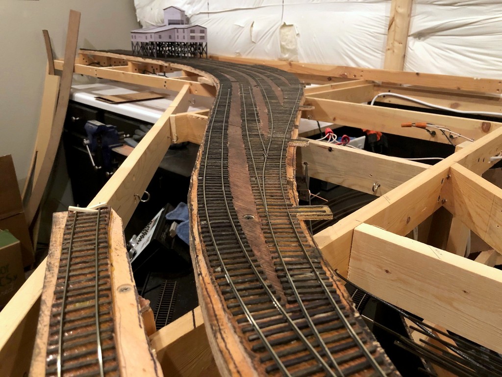
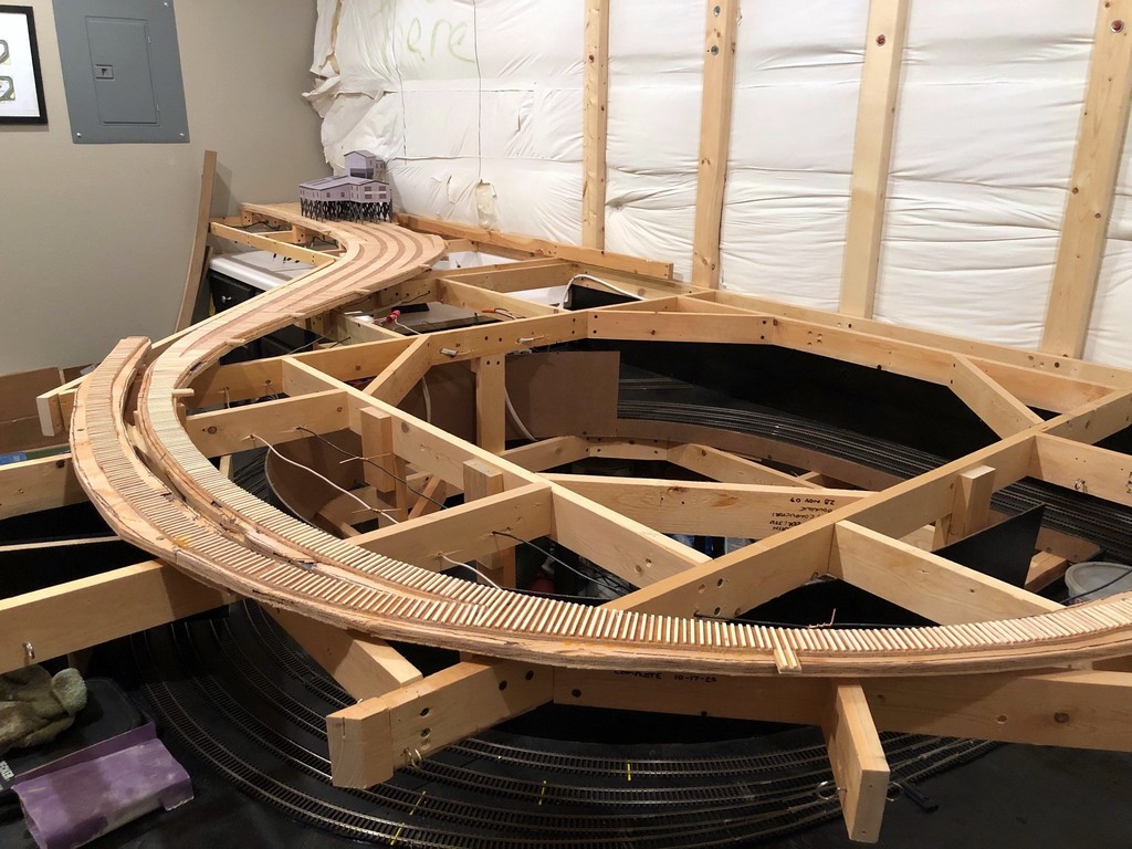
Made some progress this week on the Mayflower Branch section of the layout. All the ties have been laid! This is a tedious but simple process made a lot easier by the outline of track left over from tracing flextrack onto my subroadbed for cutting. I just place the material (1/4″ door skin for me) on top of the layout, place thumbtacks in the holes of a piece of limber Atlas flex track, fasten the track down with the pins using turn radius templates and “eyeballing” the rest, then use a pencil to trace down both sides of the track. For marking switches, I leave a portion of the track fastened and move the loose section to trace the divergent track. After tracing, where the pencil marks diverge is the location for the turnout points and longer block ties. After the subroadbed is secured in place with risers, screws and glue, I’ve got a perfect template for the tracks on the layout for laying ties (more about making and laying ties below).
Overview of the Mayflower Branch section of the layout with the ties freshly installed (this one’s for you, Bill)
Now that all the ties are in place and I have the mock-up of the Mayflower Tipple, I can really start to visualize the entire scene. I’m really liking how the track snakes into the scene, and I think the gentle curve into the tipple will really look cool with strings of hoppers hanging out. You’ll also notice the tracks run into the wall–I didn’t have enough room to model the empty yard, just some space for empties above the tipple. This was an easy compromise to make for space because the empty yard at Mayflower was a stub-ended affair, so crews still had to run around and shove cuts of empty hoppers, just as they’ll need to do here. I can’t wait to get the rails down and operate that first mine run! There’s a lot of rail-laying between now and then, but it’s good to see it coming together.
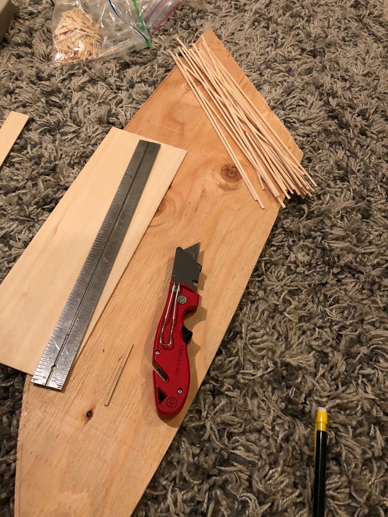
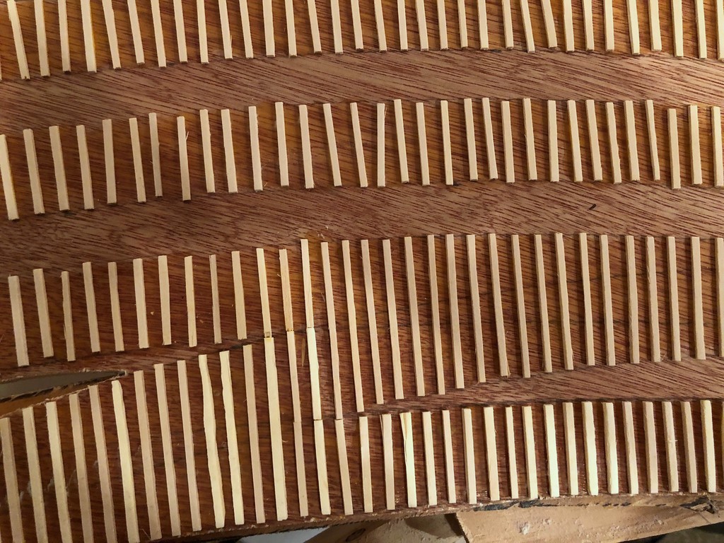
My “workbench” for making ties–I cut strips from 1/16 and 3/32″ basswood to use for siding and mainline ties, respectively.
Making Ties. Rather than buy bags of ties, I cut my own from sheets of basswood, 1/16″ for siding ties and 3/32″ for mainline ties. It’s not that ties on the prototype were different heights, but using different height ties on the layout keeps siding tracks a little lower than the main (very prototypical). I use a “spacer tie” to line up a metal straightedge the proper distance from the edge of the basswood board, then cut it with a couple strokes of a sharp utility blade. Most sheets come in 2′ length, and I’ve found it easier to cut it to 1′ length first so I don’t have to move the straightedge in the middle of a cut. With a bunch of sticks in hand, I then use a Northwest Shore Line “Chopper II” (amazing tool) and a scale rule to cut the ties in .5′ increments from a scale 8.5′ to 16.5′ with a separate, well-marked ziploc baggie for each size and length. Standard ties are 8.5′, and switches require a few of each longer size as you progress up the switch with 16′ ties for block ties at the points.
Ties tell a story about the type of track you’re modeling from mainline to well-used siding
Laying Ties. Laying ties is a simple matter of putting down some wood glue on the subroadbed and placing them. I work in sections of about 8-12″ at a time to make sure the glue doesn’t dry before the tie gets there. Ties tell a story about the kind of track you’re modeling, and it’s one of the reasons I love hand-laying track. Mainline track should be in good working order with closely spaced ties perpendicular to the rails and just a little side-to-side variation. Well kept sidings are similar but with perhaps a bit wider spacing between ties. For old, well-used sidings like you’d see at coal tipples, I’m pretty haphazard with my ties, allowing some of them to kink off perpendicular and lots of variation in spacing and alignment from side-to-side. It looks absolutely disgusting before the rails go on, but the effect is more subtle once the ties are stained and the rails are in place. I love disgusting looking track that still runs well, so I can be pretty aggressively messy when laying siding ties!
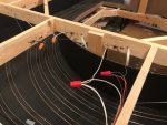
This post is less of an update and more of an effort to chronicle a minor but important part of layout construction: DCC track bus planning. Installing DCC has two major components, the first is wiring up the DCC system with its command station, booster(s), throttle panels, computer connections, wireless throttle receiver, and network cables–I covered the installation of the DCC and logical connections of the DCC system here. The second component of DCC is installing the wiring for the track which includes electrical buses, circuit breakers, and dividing the layout into zones which I’ll cover here. Even if you don’t plan to use circuit breakers, its still a great idea to “future proof” your layout by wiring for zones–you can always tie the zones together at the booster, but you don’t want to be installing new buses and feeders under finished scenery. These zones will also help with electrical troubleshooting if you can’t find a short–you’ll at least be able to isolate it to a smaller section of track.
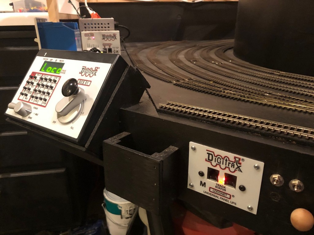
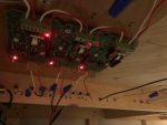
This UP5 panel’s Loconet light is connected directly to the booster (note the “M” label for “master”)
My layout is small enough to easily be powered by a single 5A DCC booster, in my case, an old Digitrax DCS100 Chief acting as a booster (a DCS51 Zephyr is the command station). At most, I’ll have 3 trains and perhaps 6 locomotives running at any given time. The DSC100 can handle this current easily, but with circuit protection provided by only the booster, if any one locomotive runs against a switch and shorts on the frog, power for the entire layout and all trains shuts off. The solution? Dividing the layout into zones and using solid-state circuit breakers!
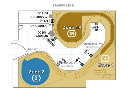
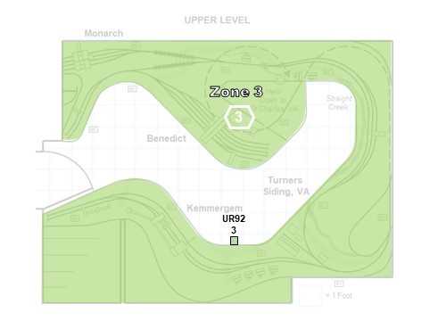
I already needed at least three zones on the layout because I have two reversing loops which need to be isolated from the main bus and powered through an auto-reversing circuit breaker. In my case, I use the On-Guard AR reversing breakers from DCC Specialties. Although a tad on the expensive side, the solid-state AR circuits are rock solid and work more reliably than their analog counterparts, especially with the current draw of sound locomotives. Aside from the reversing zones, I decided to divide the remainder of the layout into 3 additional zones, one per level. How many zones you use is a balance of cost and functionality–too many, and the cost quickly gets out of hand along with the wiring (each zone needs its own wiring bus), too few, and operators causing short circuits will quickly ruin the fun of other operators in the same zone.
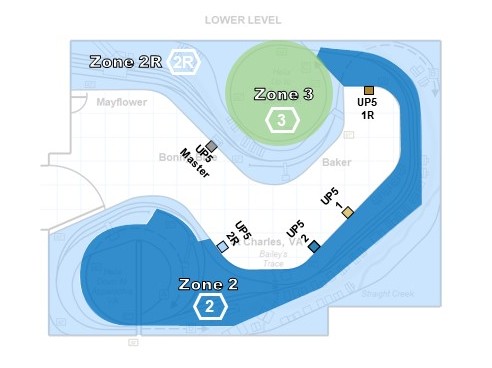
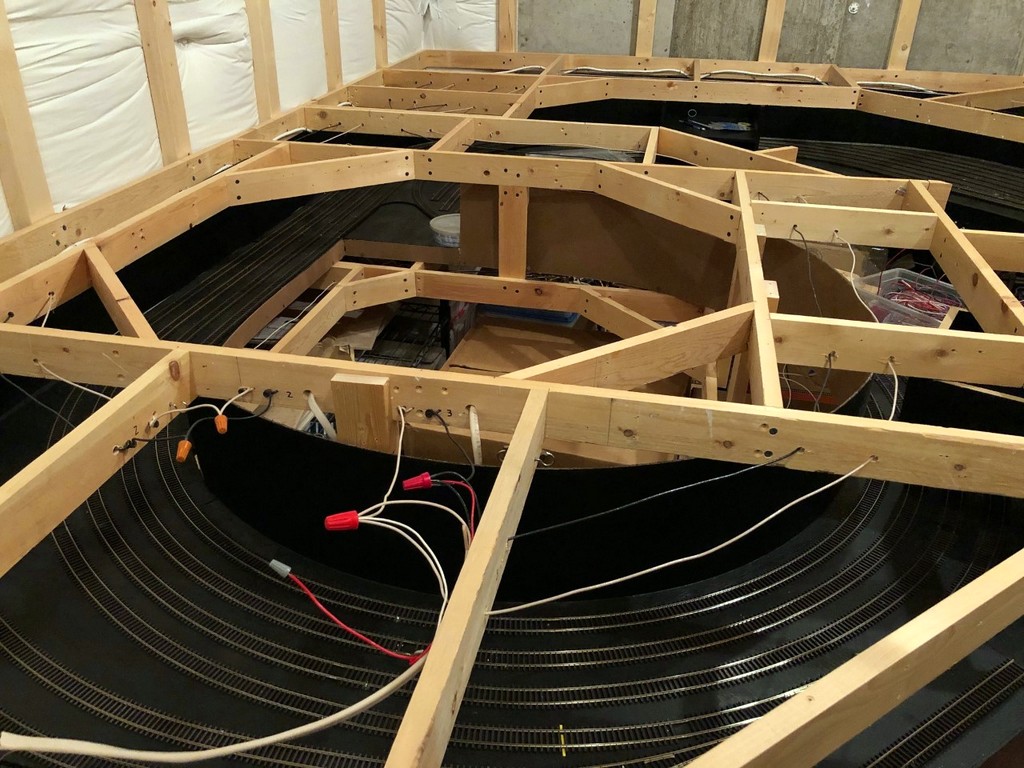
With my max of three trains in mind, I drew zone lines primarily to ensure each train would be in its own zone most of the time. Consequently, the zones are different sizes based not only the amount of track it powers but the operating locations for the trains. For example, zone 3 is the largest on the layout and powers not only the entire upper deck but the helix between the lower and upper decks as well. That’s a lot of track, but only one train at a time will venture to the upper deck, so it can be large. The main level is two zones with one covering the wye and yard at St. Charles, and the second (a reversing zone) covering the branch to Mayflower–there will often be a train at St Charles while another works the Mayflower Branch. Finally, I made the staging level its own zone (along with a second reversing zone) so that operators moving things in and out of staging won’t impact operators on the visible portion of the layout.
Once I knew where the zones would be, I ran an electrical bus from the vicinity of the booster all along the benchwork where the tracks of that zone would go. I’m all about overkill here, so I use household Romex 14 gauge copper wiring that I pull out of the sheath. I drill holes and run the black and white wires through the benchwork about 4″ apart. One important step is to LABEL THE BENCHWORK with a Sharpie every few pieces of wood, especially if you have multiple buses running side-by-side, so you don’t become confused as to which track you’re hooking up to what zone–if you mess this up, your track could be wired to multiple zones simultaneously and eliminate any benefit of electrically isolating the zones. At the ends of the run, I just wrap the lines around a drywall screw. If I need to run a bus in two directions, I just make a junction and join the three wires together with a wire nut, just like I would do with household wiring.
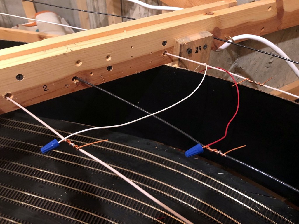
Pigtails on the DCC bus, note the zone IDs (2 and 2R) marked on the benchwork
I strip about 1″ of insulation off each wire about every 2-3′ where it will connect to track, and I wrap a 4″ section of the uninsulated ground wire from the Romex around the bare spot about 3 times leaving 1″ or so hanging off both ends. A little solder keeps this pigtail in place. I’ll offset the white- and black-line pigtails by about 4-6″ horizontally in addition to the distance between the wires to minimize the risk of shorts. These pigtails become the connection points for track feeders using wire nuts. Of course, you’ll need to physically separate the tracks between zones by either cutting gaps in the rails or using a plastic insulating joiner. Be sure to overlap your gaps by 3/4″ – 1″ for zones connected to an auto-reverser!
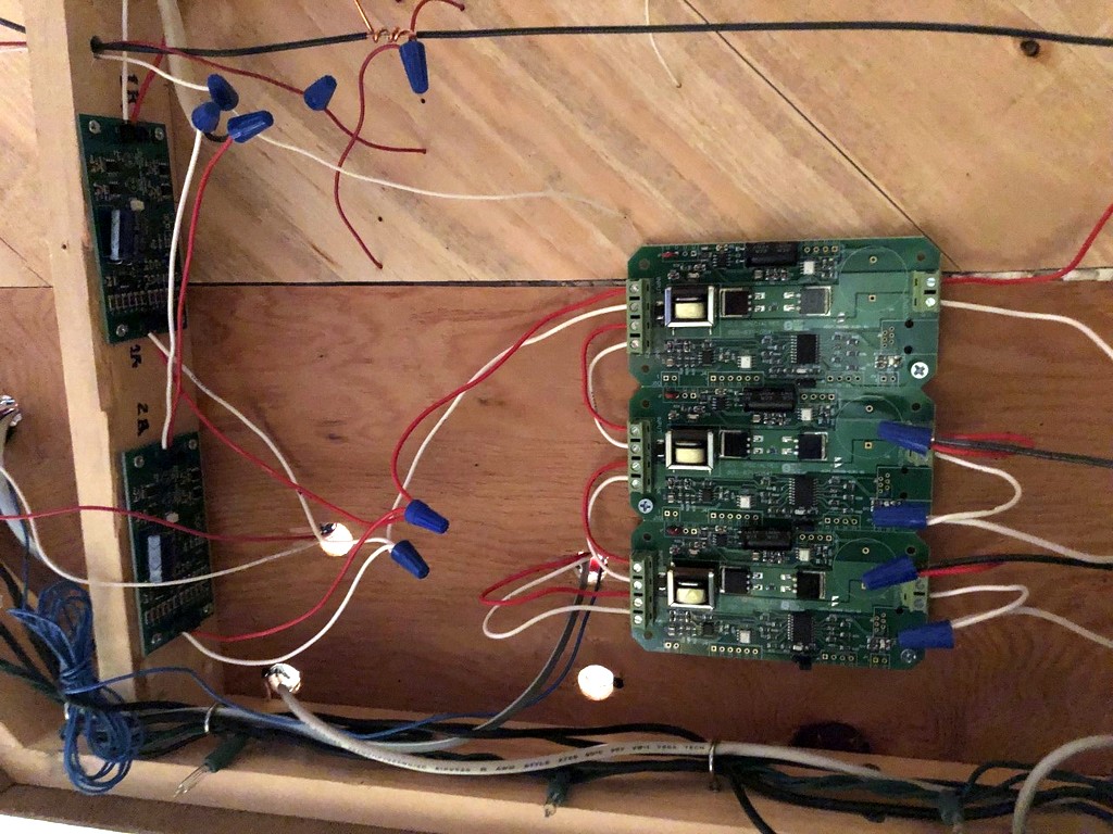
Between the bus for each zone and the booster is a circuit breaker, in my case a PSX-3 (essentially 3 PSX-1s) from DCC Specialties (I covered how to program these with a DCS51 here). Like the auto-reversing breakers, the PSX breakers are solid-state and are well worth the money over analog breakers, especially if you’re running sound locomotives. I have been extremely impressed with these units so far! The PSX design makes it easy to daisy-chain multiple breakers with just one set of wires to the booster. The only split I had to make was after the PSXs when I had to run the last booster connection off the PSX to the two AR circuits. To make the connection to the buses easier, I made a simple “panel” on part of the benchwork where the 14 gauge wires for each bus come through, get wrapped around a drywall screw, and have the ends exposed for connection to the PSX via smaller wires connected with wire nuts.
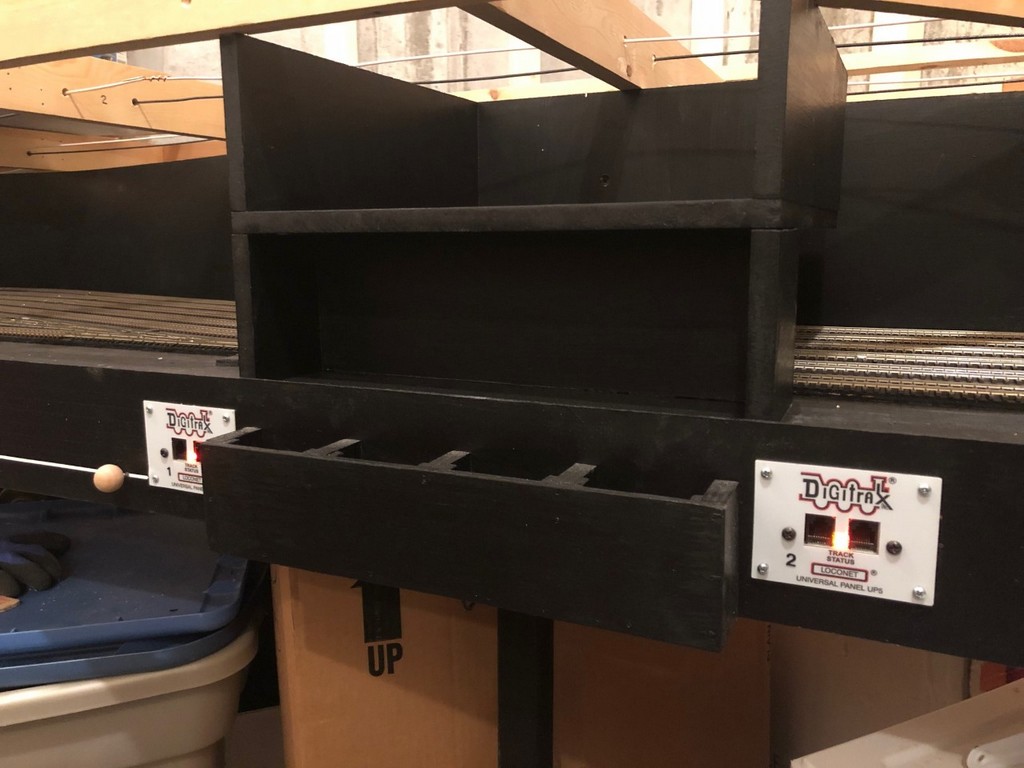
Zone 1 and 2 indicators using UP5 Loconet lights
A final step for me was figuring out a way to monitor each zone to know what’s active and what’s shorting out. It’s more difficult to detect a short with the PSX than the DCS100 because the booster makes a distinct noise when it’s reacting to a short, but the PSX is silent. For monitoring, I turned to the Digitrax UP5 universal interconnector panel. I have five of these panels at various spots along the fascia of the staging level for connecting throttles, and each has a “track status” light that can be wired to the track bus. I chose one in proximity to each zone to be the “zone indicator”, labeled with a sticker for the zone number to help me remember, and wired it to pigtails of the corresponding track zone. This way, if a short occurs, only one light corresponding to the affected zone will go out to aid troubleshooting. I wired the UP5 adjacent to the command station and booster directly to the booster wires (no circuit breaker in between) and labeled it to be the master monitor–if it’s on and everything else is out, it tells me the problem is somewhere in the circuit breaker wiring.
Finally, I drew pictures (the ones seen here) of the zones on top of a layout diagram to help me remember exactly where the zones go, and I placed this in my layout binder with all the other helpful information on the layout. This wiring took a good bit of time to plan out and install, but now the layout has the robust electrical backbone to make for smooth connections, easier troubleshooting, and ultimately more fun for operators.
PSX-3 circuit breakers and adjoining bus routing panel using drywall screws (note the zone 3 bus has not been installed yet)
Bus junctions are easy using wire nuts to join 14 gauge bus wires (household Romex)
I haven’t added an update for a while because the layout doesn’t really look any different. That’s not to say I haven’t been working, it’s just been all the boring stuff – wiring. It may be boring, but if you want your layout to run well, it’s doggone important, so it shouldn’t be left as an afterthought.
First, I corrected an issue I first noticed when running trains around the staging level – sound! I never ran sound locomotives on my previous layout, and now that I’ve got a few, I noticed how annoying it is to have diesels sitting in staging making idling noises that are easily heard throughout the room. These trains are supposed to be dozens of miles away, and I don’t want to hear them while they’re in staging. Of course, there’s the option to “mute” a sound locomotive temporarily, but I don’t want to force operators to go through an entire consist muting and unmuting every time they pick up or drop off a train in staging (and every time a short occurred, all the sound would come right back on anyway). For a solution, I went “back to the future.”
I installed a small SPST toggle switch (picked up 20 for cheap on eBay) for each staging or locomotive track (9 total) on the fascia where the track diagram will be. Unfortunately, this meant pulling dozens of feeders from the staging tracks and running a secondary bus for one rail under each track that’s connected to the switch. Thankfully this didn’t involve any de-soldering because all my feeders are connected via wire nuts. Now I can turn off the power to any staging track with sound locomotives until they’re needed, and all the operator has to do is flip a single switch. Old school “electrical block” solution to a DCC problem.
While I was at it, I broke down and ordered a DCC Specialties PSX-4 solid-state circuit breaker to go with my On-Guard-AR auto-reversing circuit breakers. I’ve been planning to do this all along and wiring for multiple zones, but after reading through the PSX documentation, I discovered my understanding of the PSX-4 and how it interacts with AR breakers was a little lacking. I didn’t know that the AR breakers should not be wired off a PSX zone but directly wired to the booster themselves. Turns out with the two reversing zones already protected by an AR circuit breaker, I really only needed a PSX-3 because I only have one non-reversing zone per level (1=staging, 2=lower level, 3=upper level, 1R=staging reverse tracks, 2R=St Charles wye to Mayflower). “Snap” – “hey look, now I have a PSX-3 and a spare PSX-1”. . . smart DCC Specialties! Not gonna lie, it was a little confusing to program the PSX to work well with the AR breakers using the Digitrax Zephyr, but I finally figured it out:
Set the Digitrax booster to .5 sec short circuit trip using booster instructions (CV 18 to “c” on my DCS100)
Solder the Digitrax jumper on each PSX zone per PSX instructions
Set the PSX to programming mode via the jumper per the PSX instructions
Ignore the part about setting the PSX address unless you need the PSX to respond to “on/off” or other special commands from the DCC (If you just need it to be a circuit breaker, you don’t)
Connect a single PSX zone directly to the Track A / Track B from the Zephyr
Turn the track power on on the Zephyr
Put the Zephyr into “OPS Programming” mode
Select CV55 (“CV”, “55”, “CV”)
Press “1” and “CV-W” (add delay to the PSX so the AR zones will trip/reverse first)
Select CV65 (“CV”, “65”, “CV”)
Press “80” and “CV-W” (set delay to 10ms which works for my setup)
If Zephyr shows “Busy,” exit programming mode and try CV65 steps again
Set PSX to ops mode via the jumper per the PSX instructions
Repeat steps for additional PSX zones
I encourage you to read all the instructions first and choose your own adventure–just sharing what worked for me.
Finally, before I lay subroadbed and track for the lower level, I had to add the wiring bus, or in this case, two wiring buses. Two are needed because the St. Charles wye needs a reversing circuit, and the reversing district carries over all the way to Mayflower. Lots of drilling holes, cutting open Romex, and pulling heavy gauge wire through. I still have to make the little pigtails for feeders, but it’s mostly done. Shouldn’t be long before I’m laying track on the main level!
Just one more 1/2 turn to go before reaching the main level
Just [almost] finished the first helix. Man, am I glad not to have to work around a floating wall for the second one! As promised, I’ve written an article on how to design and build a helix that’s strong, reliable, easy to build and an efficient use of space and material–it’s a design I call the “Double Pinwheel Helix.” I’ve built two helices this way now, and I haven’t seen another design that comes anywhere close to being this simple to build using nothing but plywood and a circular saw (no jigsawing for hours), and it’s very forgiving if you don’t cut the pieces exact or your space is a little wonky.
Rather than post it here, I put the article on Appalachian Railroad Modeling where more people would be able to find it and hopefully be inspired to overcome their fear of building a helix. You can find the article here. Here are a couple of photos so you can see the progress.
The key to the double pinwheel design is lots of clamps to ensure the lamination of pieces is thorough
I’m taking a pause on construction to work all the bugs out of the staging level before building on top of it, so I thought I’d share my method of building manual switch control mechanisms that operate from the fascia. I developed these mechanisms for my last layout, and since they proved to work so reliably, I’m doing the same on my current layout. What I like about these mechanisms is they’re rock-solid, easy to use, and unlike alternatives such as Caboose Industries ground throws, they keep fingers away from the scenicked area of the layout. As an added bonus, using a DPDT slide switch as the “guts” not only gives it a “snap”, but it makes it easy to power frogs and LED indicators if you want them.
The Design
The figure shows most of the relevant parts of the mechanism. It’s essentially a DPDT slide switch mounted to a piece of 2×3″ lumber for the mechanism, a piece of .062″ music wire and a 3/4″ round wood ball for the control arm, a piece of .025″ music wire for the throw, and pieces of 3/32″ and 1/16″ brass tubing where the music wire needs to go through wood.
Making the Parts
The top portion of the throw bell crank made from music wire
I create the throw first by drilling a snug hole for the piece of 1/16″ tubing about 5/8″ from the throw bar of the switch. I normally drill this dead center between the rails on the frog side of the throw, but if you have benchwork interfering below, you can put this anywhere along the throw bar on either side. I’ve found 5/8″ distance works well with the DPDT switches I use–anything shorter and it won’t throw far enough; anything longer, and the wire is not stiff enough for a reliable throw. I cut a piece of 1/16″ brass tubing just long enough to reach the bottom of the subroadbed while remaining just a fuzz above the ties on top and gently tap it in with a hammer. Next I drill a hole large enough for the .025″ music wire in the throw bar adjacent to the hole for the tubing. I cut a piece of .025″ music wire about 4-5″ long and bend one end to fit perfectly into the throw bar (clipping it to avoid dragging under the throw bar) and dropping into the tube. While holding down the top part of the wire, I reach underneath and bend the other end of the wire as tight as I can by hand opposite the direction of the throw and perpendicular to where the control arm will go–it doesn’t matter that the bell crank is in line with the throw; it matters that it’s perpendicular to the direction the control arm will need to move. Finally, I use a pair of needle-nosed pliers to bend the wire toward the ground about 3/16″ from where it exits the bottom of the tube. The bell crank is now complete, and you should be able to easily throw the switch by moving the bottom of the wire back and forth.
Switch mechanism ready for mounting sitting next to its control-arm wire
Next I build the mechanism. First I solder feeders onto the DPDT switch–I use red and white for the connections to the track bus and gray or blue in the center for the connection to the frog. Next I cut a piece of 2×3″ lumber about 2 1/2″ long (you can use any size, but smaller will be more delicate, and larger will be tougher to fit around benchwork). Then I a notch about 1″ deep just wide enough for the DPDT switch to fit. At this point I designate a “top” of the mechanism and install the DPDT switch with small wood screws. With the mechanism placed between the throw and the frog, the feeders should be REVERSED from the normal orientation of your track bus. In other words, my track bus is normally oriented red/black-front, white-back, so I install my DPDT switch with the white feeder in front. Finally, I drill two holes through the slide portion of the DPDT switch, one just big enough for the .062″ control wire and the other closer to the tip of the switch for the .025″ throw wire. I’ve found drilling both holes with the smaller bit and then enlarging one prevents the plastic from breaking. I put a little countersink into the top of the holes by spinning an X-Acto knife in them to make it easier to insert the wires. NOTE: my switches are hollow inside which makes it a bit of a pain to insert the wires sometimes–it just takes a litte patience. I finish by drilling and countersinking two holes where I want the screws for mounting it to the layout will go.
The next step is the control arm. First I decide where I want the control knob on the fascia. For me, I use a simple track diagram on the fascia with switches drawn in (more on this in a later post), so I draw the diagram first, then drill the hole that will tightly fit the 3/32″ brass tube perpendicular to the ground and aimed toward the end of the throw crank under the layout. Then I cut the 3/32″ brass tubing to fit just through the fascia and 2×3″ board edging the layout. In some spots, there is no board, so I’ll glue a square piece of 2×3″ lumber behind the fascia to ensure adequate support. There might also be other lumber between the fascia and the switch. If its a fairly short distance (<12″), I’ll drill a 5/8″ hole where the control arm will go through. If it’s a longer distance, I’ll drill a second hole for 3/32″ tubing in line with the first–this isn’t tough to do if you take a piece of straight .062″ wire, push it through the fascia tube and mark where it hits the intervening lumber. The straigher you make these two tubes, the smoother the mechanism will be. Finally, I bend a control arm. Starting at the switch end, I bend the last 1″ 90 degrees toward the ground where it will go through the slide switch, then I make a slight bend downward about 1″ from the 90 degree bend toward the fascia hole, then another bend about 1 1/2″ from where it will go through the 3/32″ tubing. The sharpness of the anlged portion depends on how much room you have between the switch and fascia and how far down on the fascia your control knob will be. The shallower the bends, the more solid and reliable the mechanism will be. I cut it with a Dremel tool and cutoff disk (enjoy the fireworks!) so it will protrude about 1 1/2″ through the fascia and file the burrs off the end.
Mounting the Mechanism
Here’s what a completed installation looks like under the layout
This part is straightforward, but it can be tricky and sometimes frustrating to get the switch is exactly the right spot–it requires some experience and skill to get it right, and that experience and skill requires some misfires and mistakes to gain. I first install two 1 1/4″ drywall screws into the mechanism mounting holes with about 3/32″ of the tip sticking through–this gives a way for the mechanism to grab the subroadbed a little while you’re placing it. Then I insert the control arm through the DPDT switch and run the other end through the 3/32″ tube(s) and out the fascia. Next I place the mechanism onto the .025″ bell crank (this part can be tricky and frustrating if the wire and holes don’t line up well). Once everything is inserted, I place the DPDT slide in the middle position and do the same with the throw topside–with both of these in the middle position and the DPDT slide direction in line with the control arm, I press the mechanism into the subroadbed and hold it in place. While holding the mechanism in place under the layout, I’ll try work the mechanism to ensure it throws snugly to both sides. This is a matter of trial-and-error, but once I’m satisfied, I’ll put one of the screws into the subroadbed. Inevitably, it will leave a gap between the mechanism and subroadbed because I wasn’t able to pre-drill the hole. . . no worries. Then I’ll start the second screw, go back to the first and back it out then put it back in to cinch it up, then do the same to the second. If all has gone well, the control arm will easily push the slide switch to both limits, and the throw will push the point rails snugly to each stock rail. If not, back out the screws and try again!
How the completed switch mechanism looks on the fascia
Once I’m satisfied that the mechanism is where it needs to be, and everything is operating smoothly, the last step is to install the control knob. I first push the control arm wire in, then cut it off with the Dremel about 5/8″ from the fascia and file smooth. Then I drill a hole straight into and about 2/3 of the way through the round wood ball. After moistening the wire and ball, I add a drop of Gorilla Glue to the wire and place the wood ball onto the wire. It should be tight enough that you have to twist it on. I like for the control knob to sit about 3/16″ from the fascia when the knob is pushed in. Work the switch a few times while the glue is wet to make sure it feels right where you’ve placed it, then let it dry. Connect the feeder wires to the track bus and the third wire to the frog and the switch mechanism is complete! While it sounds like a lot of steps, if you mass produce the 2/3″ mounts and DPDT switches with pre-drilled holes and wires pre-soldered, you can install 3-5 mechanisms in an hour.
The top portion of the throw bell crank made from music wire
Hammering the 3/32″ brass tube through the fascia–the tubing should fit snugly. the board and clamp are holding a piece of 2×3″ lumber onto the back side of the fascia to add stability.
Two holes drilled into the DPDT switch lever, one for the control arm and one for the bell crank
Switch mechanism ready for mounting sitting next to its control-arm wire
Here’s what a completed installation looks like under the layout
How the completed switch mechanism looks on the fascia