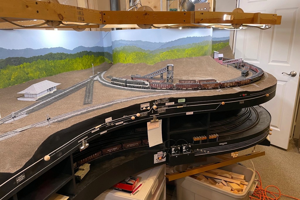
The first layout lights are in! Here’s the “cool white” that I like for daytime
While my light is nowhere near as impressive as God’s light in Genesis, it still makes me glad to see a little more light on the trains in the basement. Now that I’ve got some upper-deck benchwork in, it opened the way to try out the layout lighting I’ve been wanting to do for a while. I’ve looked into LED strings and other bundled lights, but in the end, I’ve settled on using individual multi-color LED “smart lights” I can control with my phone. It’s not the cheapest solution (about $7 a bulb, and my layout needs 40), but it’s bright, and they’re customizable for a dizzying array of colors and brightness!
This is a more modern evolution of the lighting on my last layout which used cheap plastic fixtures and compact 40W lightbulbs. I was able to recycle the fixtures and wiring for this project, but the technology is so much better than my previous little analog dimmer. Not only are the LEDs brighter, but they run cooler, only use 9W each, and I can get a nice “cool white” that looks a lot more like sunlight than incandescent lights. I was also able to play around with the colors and dimmer, and a wide range of effects are possible including a nice moonlit night and a warm sunrise/sunset. It’s also easy to “group” them so one command changes all the bulbs simultaneously.
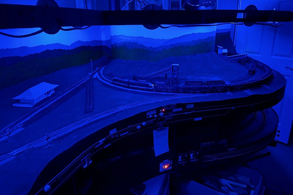
The dimmable, multi-color LEDs can give a lot of different moods like this “moonlit night”
I’ll keep playing with them to try to mitigate the glare spots and shadows. I’m also going to figure out a way to automate going from nighttime to sunrise to day–I’m sure it’s possible with all the Smart Home controls out there now. One thing I hadn’t counted on is the lit portion of the bulb is about 2″ further out from the fixture than the old incandescents. For now that’s creating more shadow along the front of the layout than I’d like. When I put the valance in for the upper deck, I’m inclined to move it out over the aisle a few inches to try to improve this, and I might mount a few of these in the overhead fixtures as well. For now, I’m calling this experiment with 8 bulbs a success, so now I’ve ordered more to keep working around the rest of the layout.
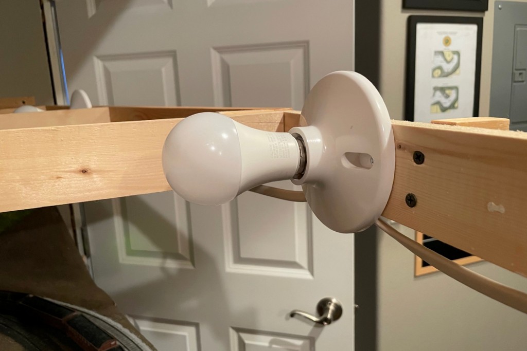
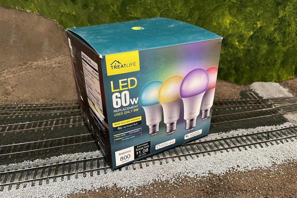
The fixtures for the lighting are simple plastic screw-in basesHere’s what I’m using, TreatLife 60W equivalent (9W actual) multi-color LED smart lights
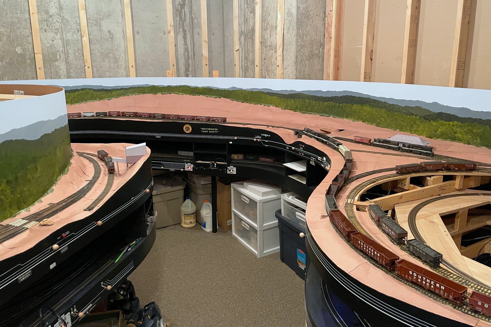
Here’s a look at last Saturday’s progress including finishing most of the lower level scenery base and painting the rest of the backdrop
I had a happy aligning of the stars on Saturday where my wife was gone for the day, I didn’t have any big “chores” to do, and I had just learned how to paint backdrops! All that combined into a day spent furiously trying to finish up the lower-level scenery forms so I could paint the rest of the lower-level backdrop. It was a good day, and I’m pretty happy with the results. I learned that the painting is my favorite part, roughing in the scenery with cardboard strips is my second favorite, and papering over the cardboard with section after section of red rosin paper is a distant third. Round 2 of backdrop painting went a little smoother than round 1 as I think I had a better grasp of the techniques, and the paint brushes seemed to work better on their second use. I liked the results of round 2 so much I went back and redid some sections of round 1.
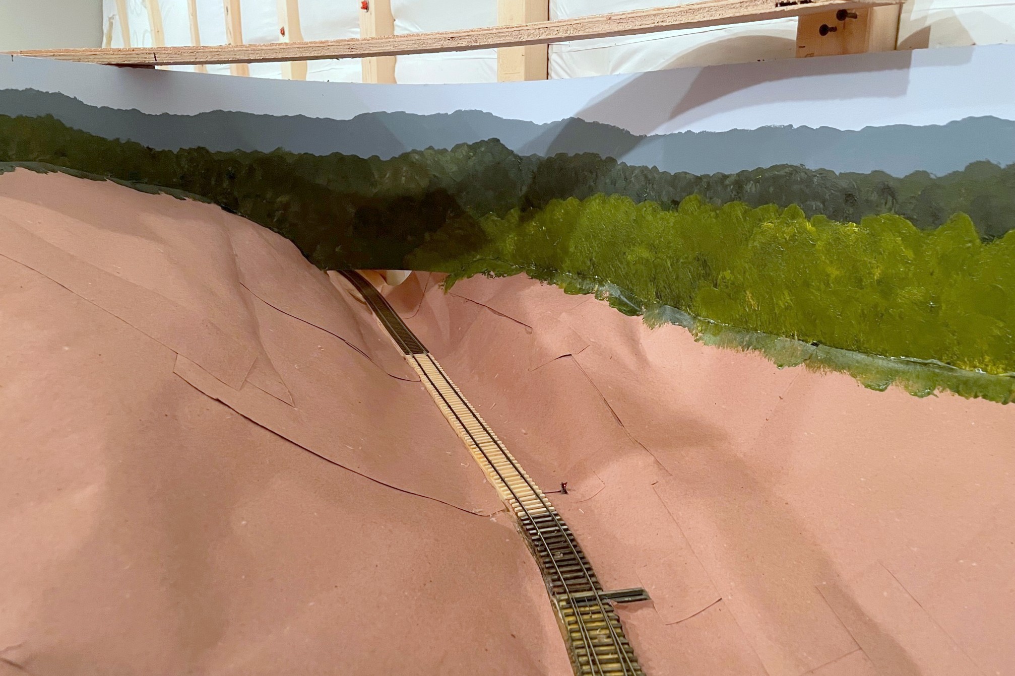
The St Charles Local traverses the wye with the newly painted backdrop. It will soon descend through the backdrop in the corner, a hole much tougher to spot now
The scenery covers over the hidden track along the back wall that joins St Charles and the Mayflower section, so I decided to do a test run… I can now verify that I can indeed – by twisting at odd angles, reaching into small gaps, and fishing it out the last couple feet with a long string of hoppers – free a stuck train from the most remote part of my hidden track! Lesson learned–when you use hot glue for scenery, it tends to leave a lot of strings hanging down, and go figure, locomotives don’t pick up electricity so well when their wheels are covered in bits of glue string! A little wheel cleaning and some extra sweeps of the hand through the area (again at odd angles via small gaps), and trains now traverse this area nicely.
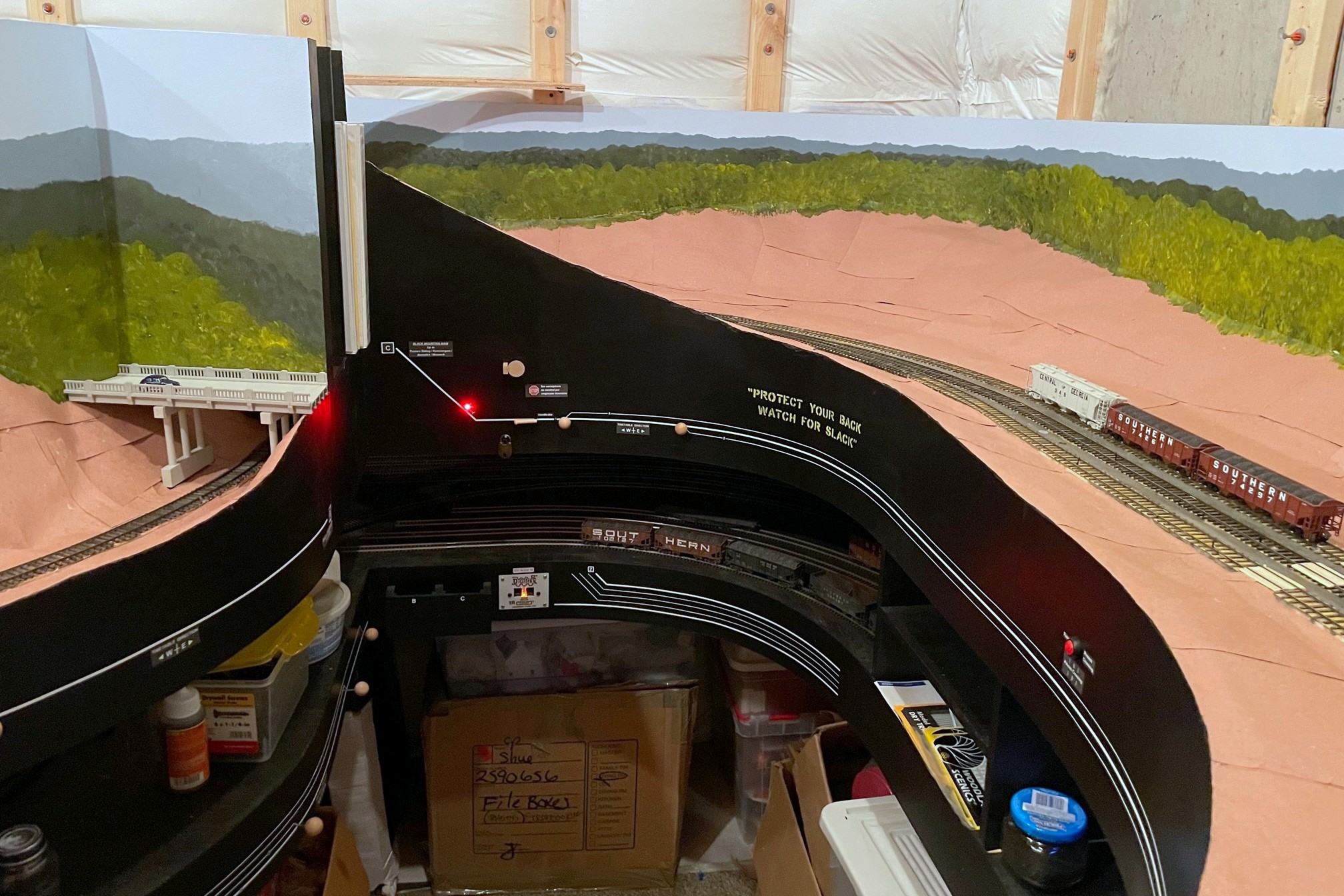
Where the two lower-level scenes transition–the backdrop on the right is lower than the left, hence less blue sky
I’ve only got one section left that still needs a backdrop and scenery forms, over the helix from staging. Painting the backdrop in the corner was the big barrier to adding this, so that will likely be the next step, and the LAST step before building upper-level benchwork… it’s getting pretty real.
Here’s where trains will leave the lower level and enter the helix to the upper level–I think the backdrop painting along with a few trees will hide the transition well
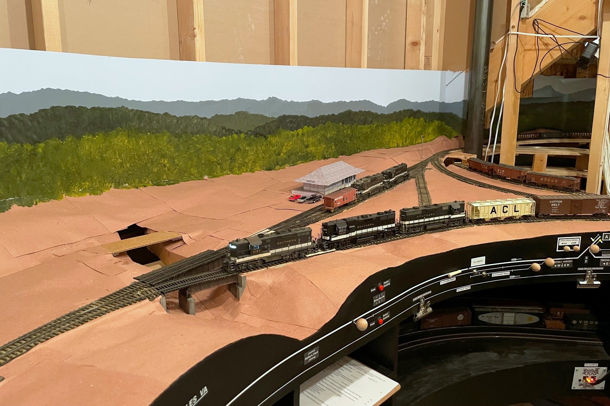
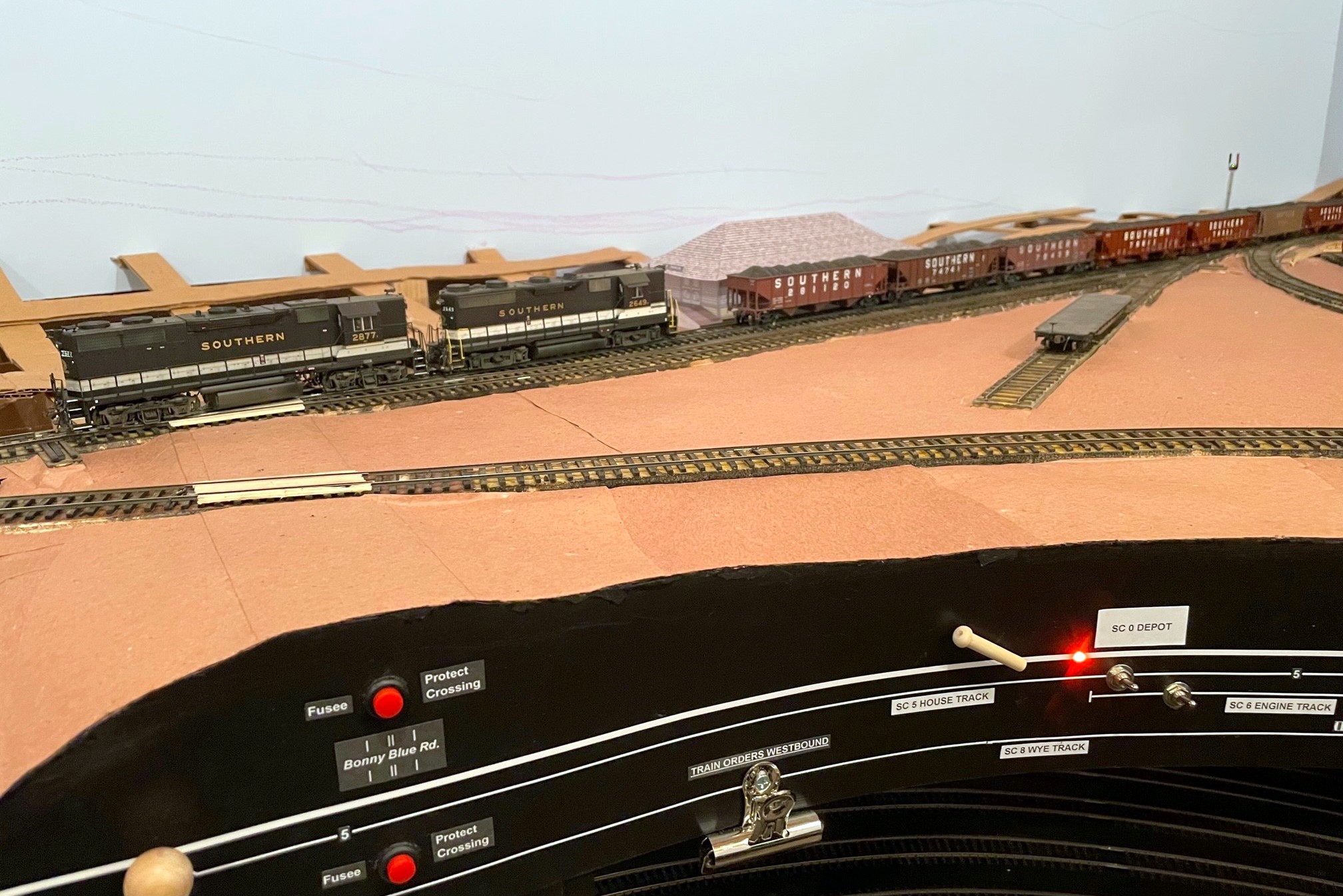
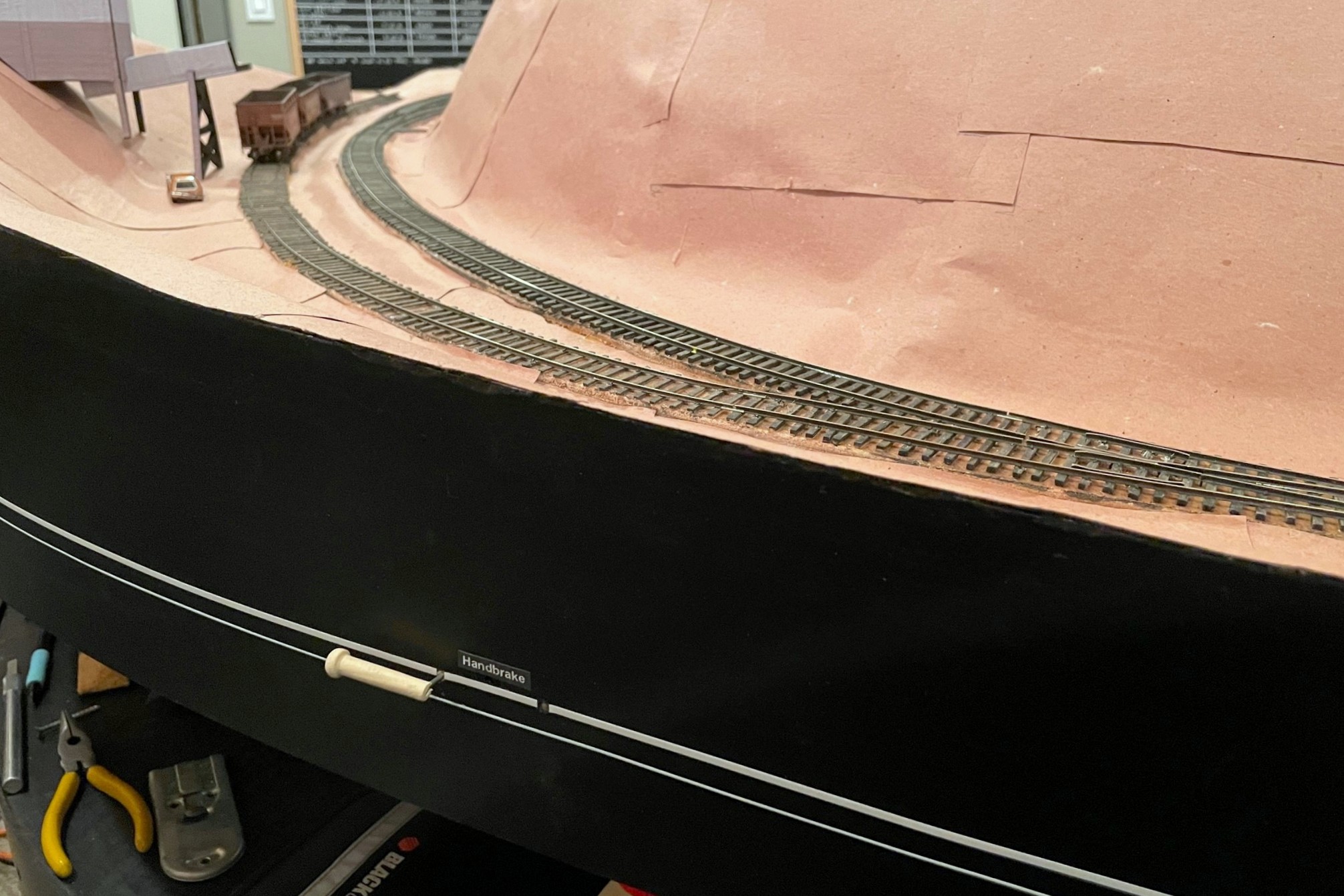
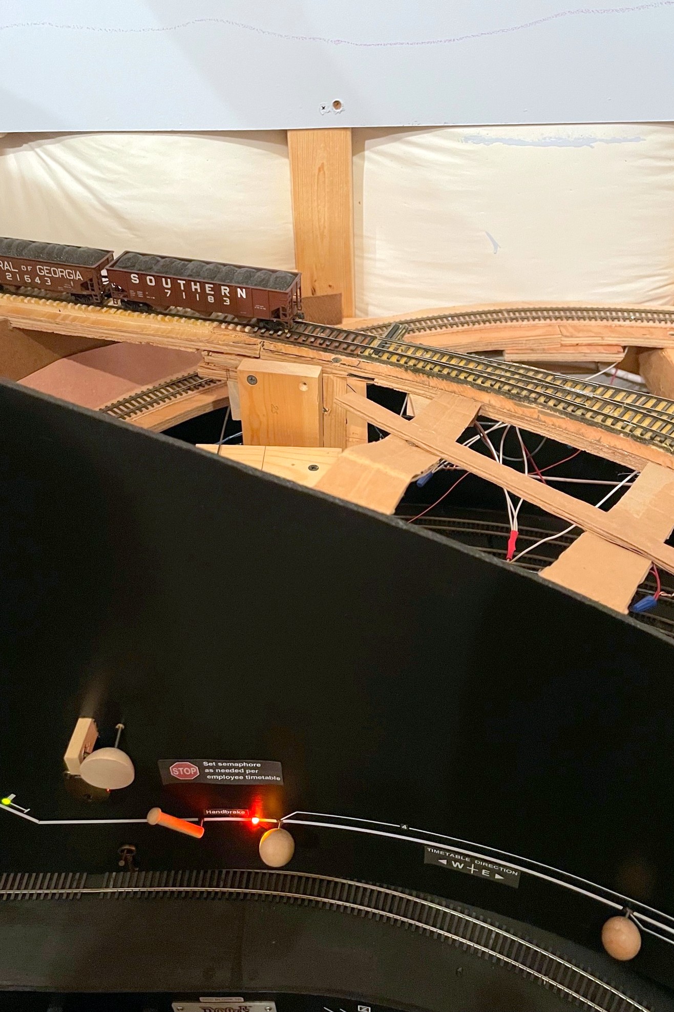
The St Charles Switcher crew sets the handbrakes to leave a string of loaded hoppers on the grade while working the yard
Gravity is a major factor in prototype railroading, but it can be quite troublesome for a model railroad. Very little real track is actually completely flat, so train crews routinely use the handbrakes on individual cars to hold them in place in yards or sidings. Not only do handbrakes hold cars in place, but in the Appalachians where I model, gravity and handbrakes were often used to move cars from empty tracks to tipple loading points, to move loads into the right track below the tipple, or even to run-around a caboose at the end of the line. Modeling working handbrakes on individual cars isn’t very practical, so what is a model railroader to do? Some install springs on the ends of a car’s axles to use friction to hold the car, but this can’t be “turned off” to allow the car to roll freely. Others use little picks they stick into the ballast to hold cars in place, but this can be destructive to scenery, and it leaves an un-prototypical giant stick next to a cut of cars. I’ve adopted a method of fascia-controlled “handbrakes” on the tracks which works well for my needs.
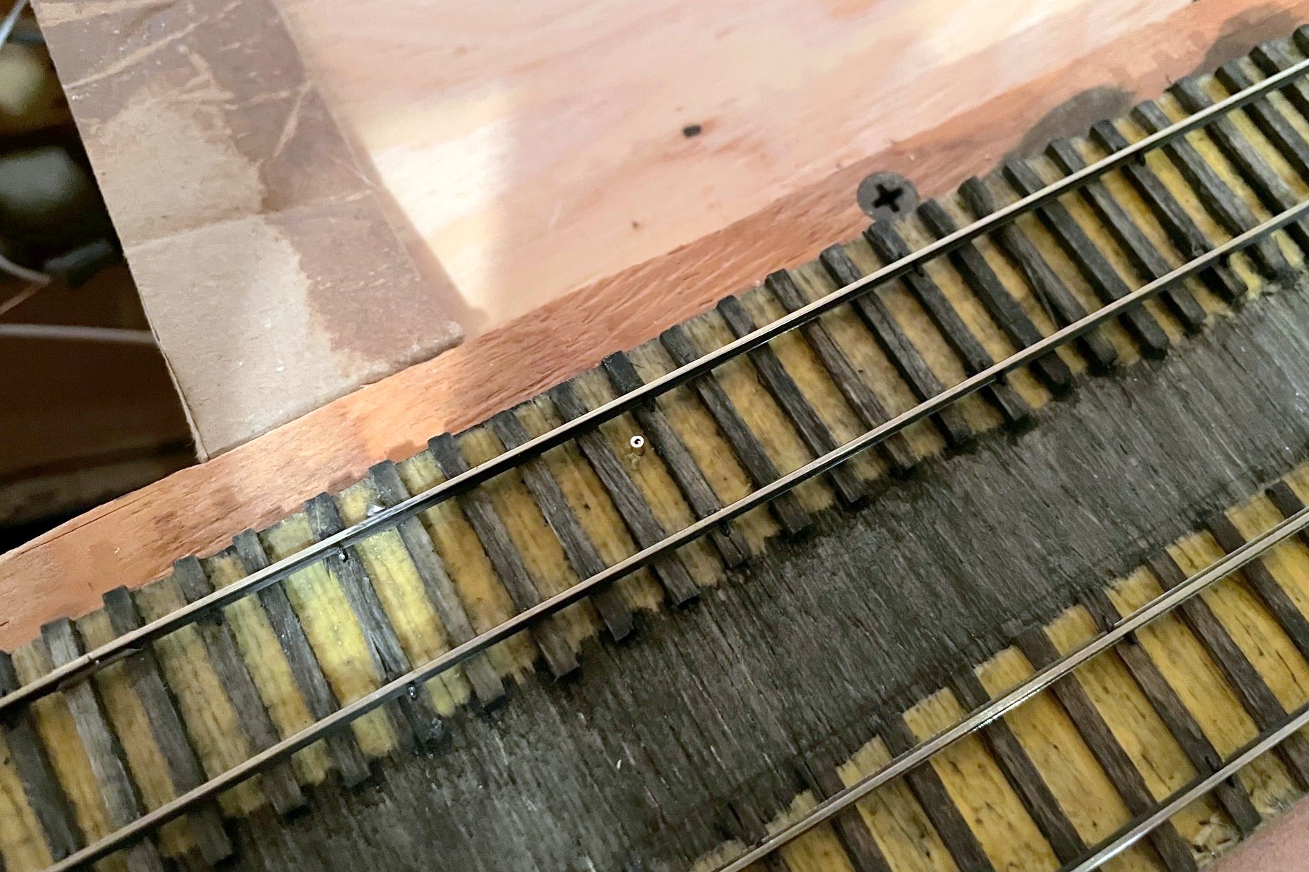
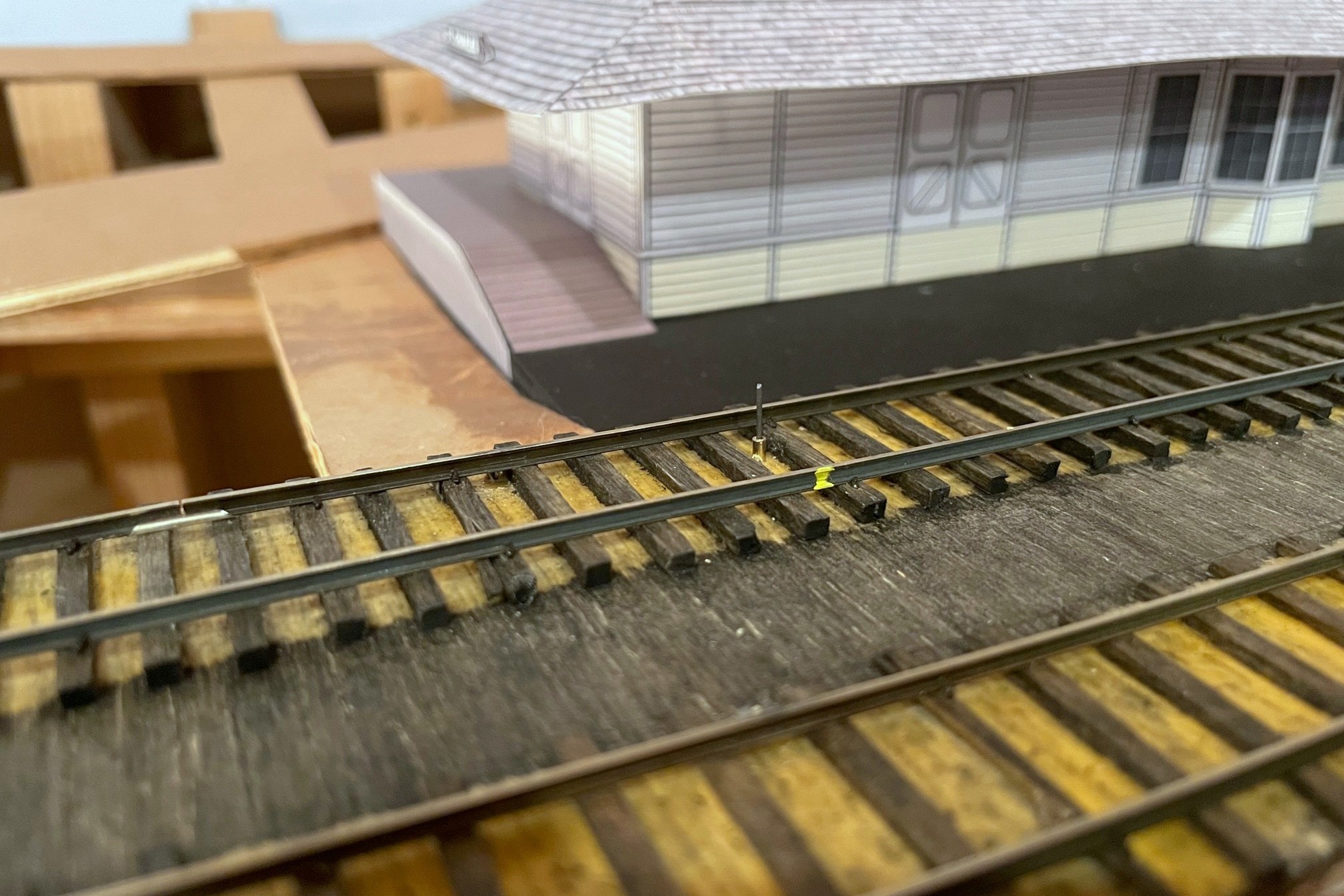
The first step of the handbrake is to locate where you want the brake, drill a hole, and insert a brass rod sleeve for the brake wire
This method is overkill if you just want to hold cars in place on a siding. For this I recommend a drop of CA, a piece of monofilament line sticking up through the tracks, or the end of a soft brush if more strength is needed–I use all of the above for holding cars in place when set out. I use the method here where I need brakes sometimes and free rolling other times, so the first thing you need to do is figure out where you need brakes. I once heard a story about a design presented to a university for a new campus that didn’t show any sidewalks. When the dean of the university asked the designer why there were no sidewalks, the designer replied “wait a year after the campus is open, then you’ll know exactly where the sidewalks need to go based on the trails through the grass.” So, where do I install brakes? Wherever I find I need them when operating trains–a question I also pose to my operators after every session: “is there anywhere you wished you had handbrakes but didn’t.” Generally speaking, they’re needed anywhere a crew will need to leave cars on a grade for a period of time to conduct other work. Since I’ve got lots of grades on the layout, I’ve currently got five handbrakes installed on the lower level alone.
The concept of these fascia-controlled handbrakes is simple: install a movable piece of strong wire between the rails tall enough to hold an axle with a mechanism to retract it when not in use. Once you know about where you need brakes, mark that spot between the rails, and make sure the area underneath is clear enough to install a brake mechanism. Remember, the brake can really be anywhere along a string of cars, so if your ideal spot is not to ideal under the layout or on the fascia, just move it a few inches. I use 1/16″ brass tube as a protective sleeve for the .025″ steel music wire I use as the brake, so once I find a spot, I drill a vertical hole between the ties for the brass rod. I like to offset the rod about 1/4-1/3 between the rails to avoid interfering with truck bolsters (coupler trip pins will also be an issue for those who use them… in fact, a similar mechanism might work for uncoupling too, hmmm…).
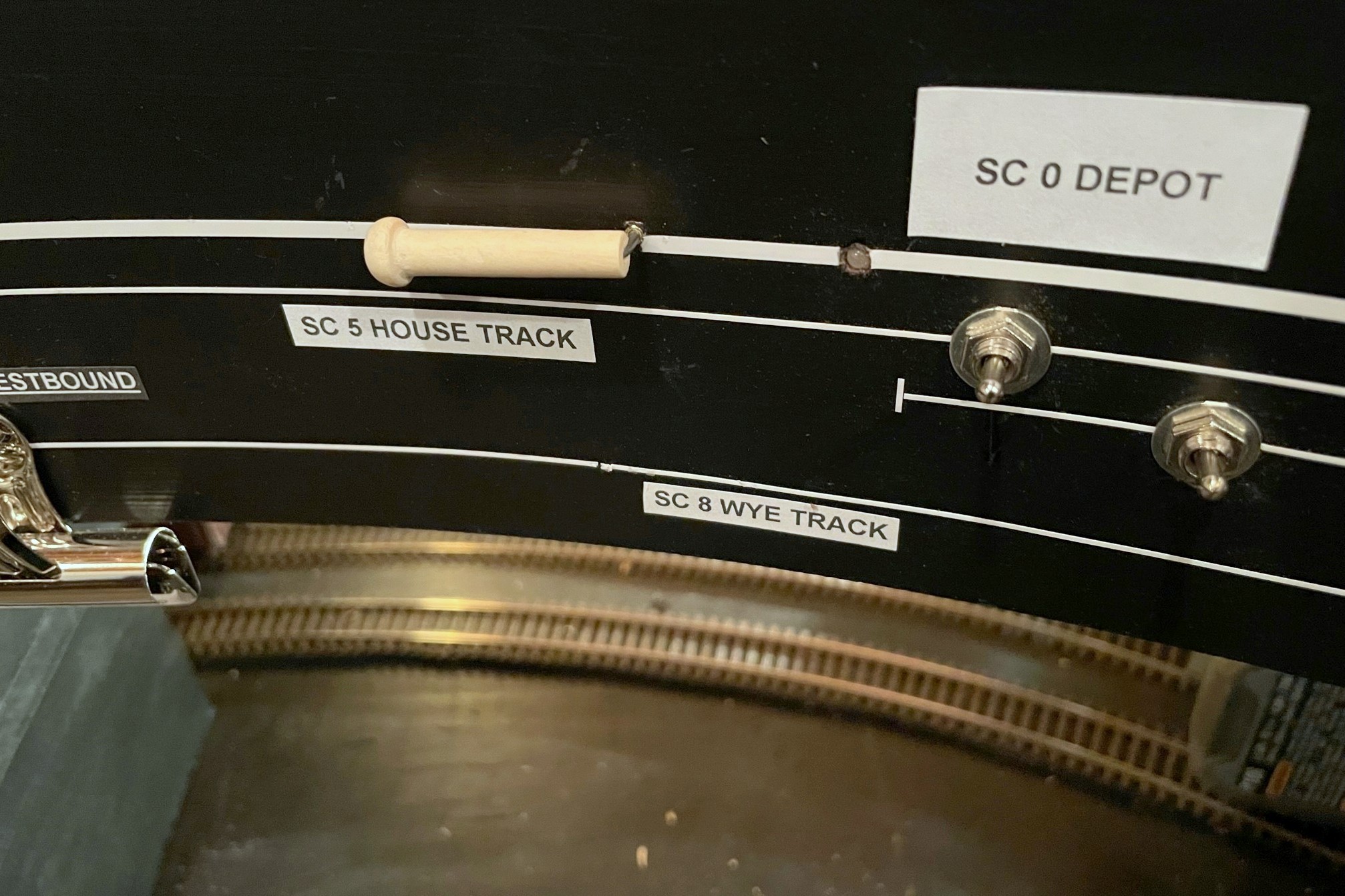
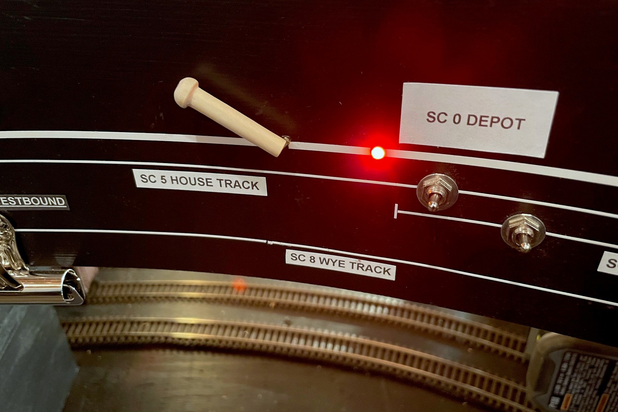
Here’s the finished control in the “off” position (in line with track)
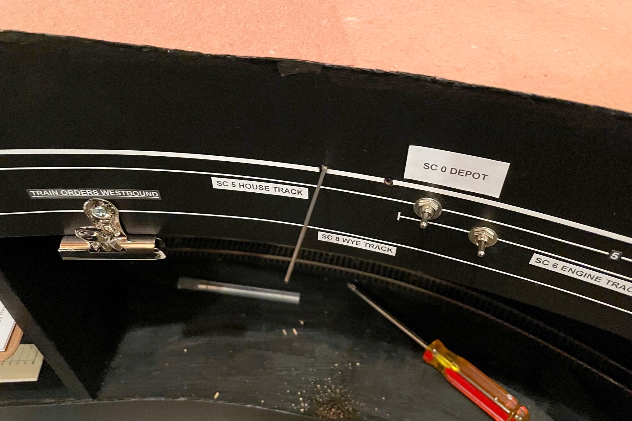
If you’ve followed me for a while, you know I’m a big fan of manual controls using slide switches–I use them for turnout controls, semaphore controls, and now handbrakes. You also know I’m a stickler for creating a fascia where the controls make sense and aid an operator instead of confusing them. In the case of the handbrake, I wanted it to be easy for operators to see when the brake is “set” and when it is retracted, so I settled on a control lever that lies in-line with the track when retracted and sits at a sharp angle when “set.” Just for good measure, I also use a bi-color LED to illuminate amber on the fascia representation of the affected track when the brake is set to help mitigate inadvertently running into a brake with the delicate footboards of a super-detailed locomotive (been there, done that).
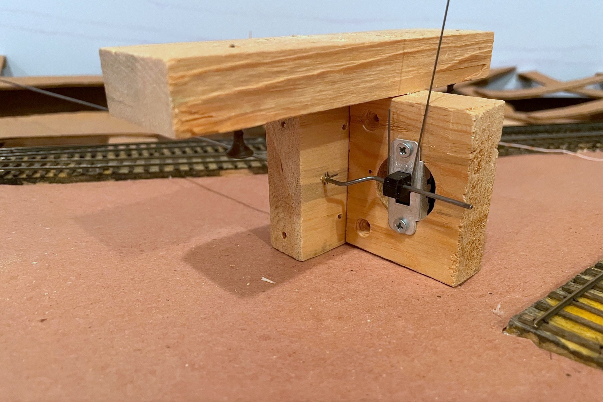
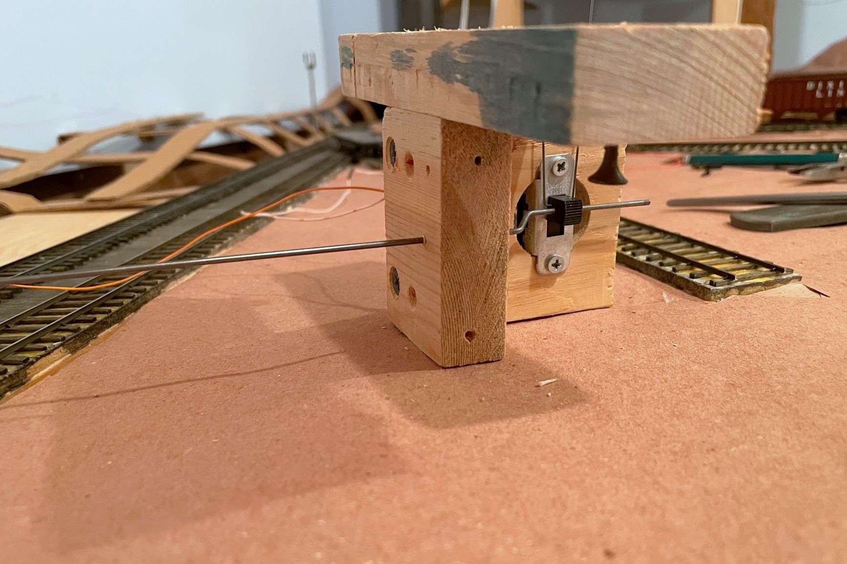
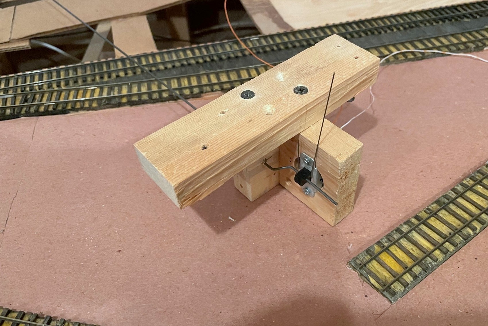
Here’s the completed brake assembly with three pieces of wood, DPDT slide switch, brake wire (vertical), and control rod (horizontal)
For the brake mechanism, I use a vertically mounted slide switch (DPDT in this case) with a 3/16″ throw–this is just enough to catch the axle of a 36″ wheel in HO scale when extended and still retract to almost rail height when recessed. The brake rod itself is a piece of .025″ music wire bent into a squared-off “J” shape running through a hole in the slide switch–initially, make this piece long enough that it will stick up about 1/2″ or more above the rails when in place. The control mechanism is a piece of thick steel rod (.062″ music wire) with a bell crank bent at one end. Th rod should be cut about 3″ longer than the distance between the brake’s track location and the location of the control on the fascia. The bell crank is offset about 1/4″ from the rod. As you can see in photos, I drill a hole in a piece of 1×3″ board centered on the slide switch and offset about 1/4″ laterally for the control rod to pass through (lined with 3/32″ brass tube for smooth operation). I also bend the bell crank at 45-degree angles instead of 90 as this allows me to make adjustments to the crank offset in either direction, shorter or longer. The structure for the mechanism is typically three boards: 1) the slide switch board with a large hole drilled out for the switch (mounted with screws), 2) the control rod board mounted 90 degrees to the switch where the bell crank is secured, and 3) the attachment board on top to make it easy to mount to the plywood sub-roadbed. I use 1×3″ pine for most of my pieces, but I may use different thicknesses of attachment plates to get the control rod at the right height for the fascia control–the brake wire can be really tall and still work, so better to have the mechanism hanging lower than to have to curve the control rod to the right height. Once I’ve got the three boards assembled with 1 1/4″ drywall screws, I disassemble it, insert the bell crank end of the control rod, insert the bell crank into a hole drilled in the slide switch, adjust the bell crank as needed for smooth operation of the switch, and reattach the boards with the screws.
The left is the front side of the assembly that will face the fascia–note the brass rod sleeve in the wood where the rod goes through
For the fascia, I drill a hole for the 3/32″ brass rod sleeve as close to horizontal as I can get it and pointed directly at the brake location on the track. I pick the spot on the fascia that allows me to do this while keeping the control rod as perpendicular as possible to the fascia (you don’t want the control rod coming out of the fascia at a strange angle if you can help it). The LEDs are nice but not necessary, but this is the step where I drill the holes, about 1″ behind the brake control. I like to drill the hole through the fascia the exact size of the LED bulb and then use a second larger bit from the back side of the fascia to create a space for the rest of the LED–this keeps the LED from popping out the front of the fascia. I use bi-color red/green LEDs which glow a nice reddish amber when hooked up to AC (e.g., DCC track bus), and I attach one lead to one side of the track bus (with a 470K resistor), the other lead to the “up” position of the slide switch, and a third wire from the center position of the slide switch to the other side of the track bus. Super simple.
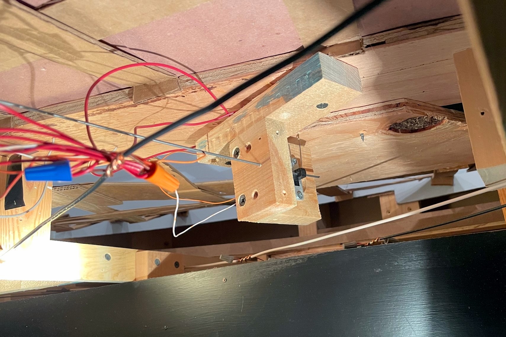
Here’s the handbrake mechanism installed under the layout–the control assembly should orient to the fascia and not the track
Mounting the switch mechanism is a bit of a pain and requires some planning and patience. From under the layout, I run the control rod through the fascia. Then I find the brass rod going up through the tracks and insert the brake rod (it helps if the brass rod is long enough to protrude beyond the plywood of the sub-roadbed). With the mounting screws on the attachment plate ready to go (screwed in so they’re almost through the board), I gently move the mechanism around until the brake wire is more-or-less vertical, the switch operates freely, and the control rod is as straight as possible between the fascia and mechanism. The mechanism is oriented to put the rod and switch perpendicular to the FASCIA rather than the track (angle relative to track doesn’t matter here). Once I’m happy with the placement, I run the mounting screws into the sub-roadbed.
With the brake in the RECESSED position, bend the control rod parallel to the ground
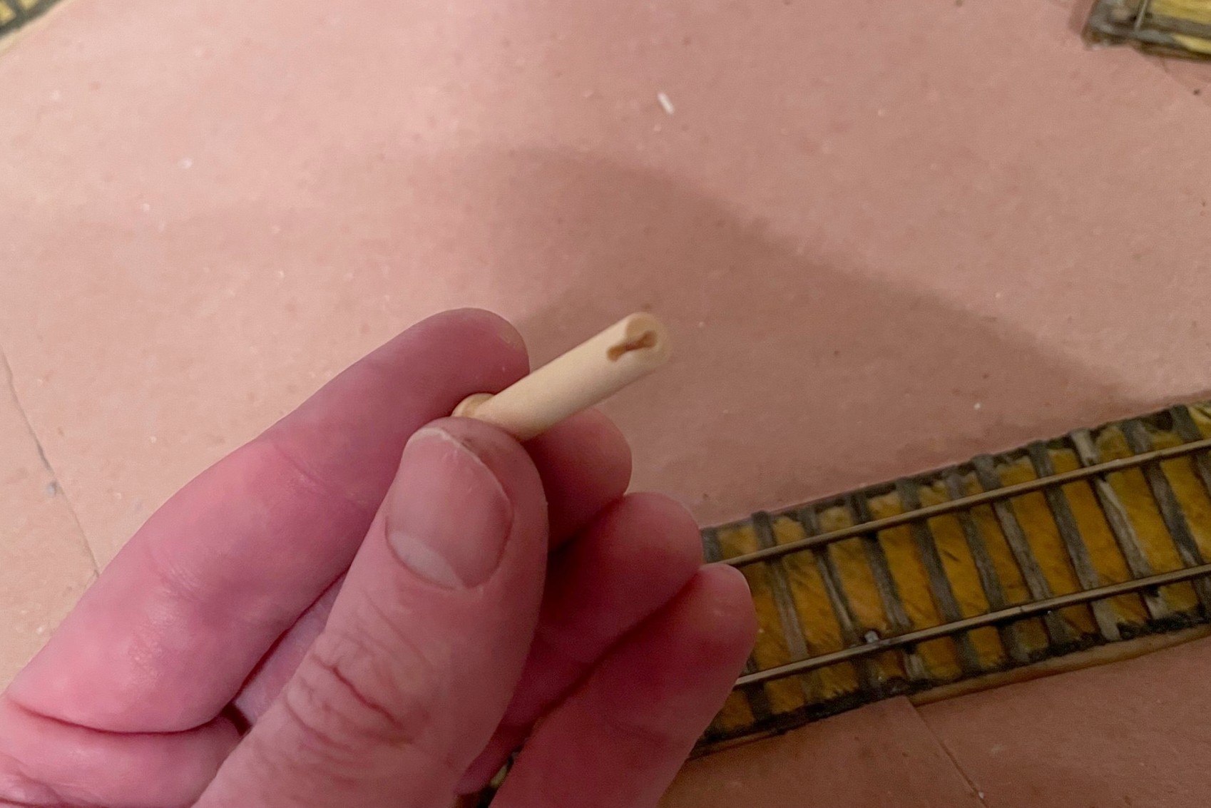
On the fascia side, I now have about 2″ of control rod sticking out. With the slide switch in the DOWN position, I then grasp the control rod with a pair of needle nose pliers flush with the fascia so the bend will be about 3/16″ from the fascia and use my hand to bend the control rod to align with my track diagram (horizontal) in the direction of the bell crank so that “up” on the control = “up” on the brake. My convention is to face the controls and bell cranks to the left, but either works. At this point, I have the leverage to test the mechanism and fix any issues. If all is good, I use a Dremel cut-off wheel to cut the end of the control rod so about 3/4″ beyond the bend. For the control lever, I use a wooden 1 3/8″ “axle peg” which can be found at any large craft store–it’s admittedly an odd shape, but it’s distinct, easy to find, and easy to use. I insert the pegs into a vice and drill a hole the exact size of the control rod about 1″ deep into the center of the peg, then drill another hole in the side about 1/8″ from the flat end into the first hole and use an X-Acto blade to create a notch between the two for the 90-degree bend in the control rod. The peg is usually a press fit onto the control rod.
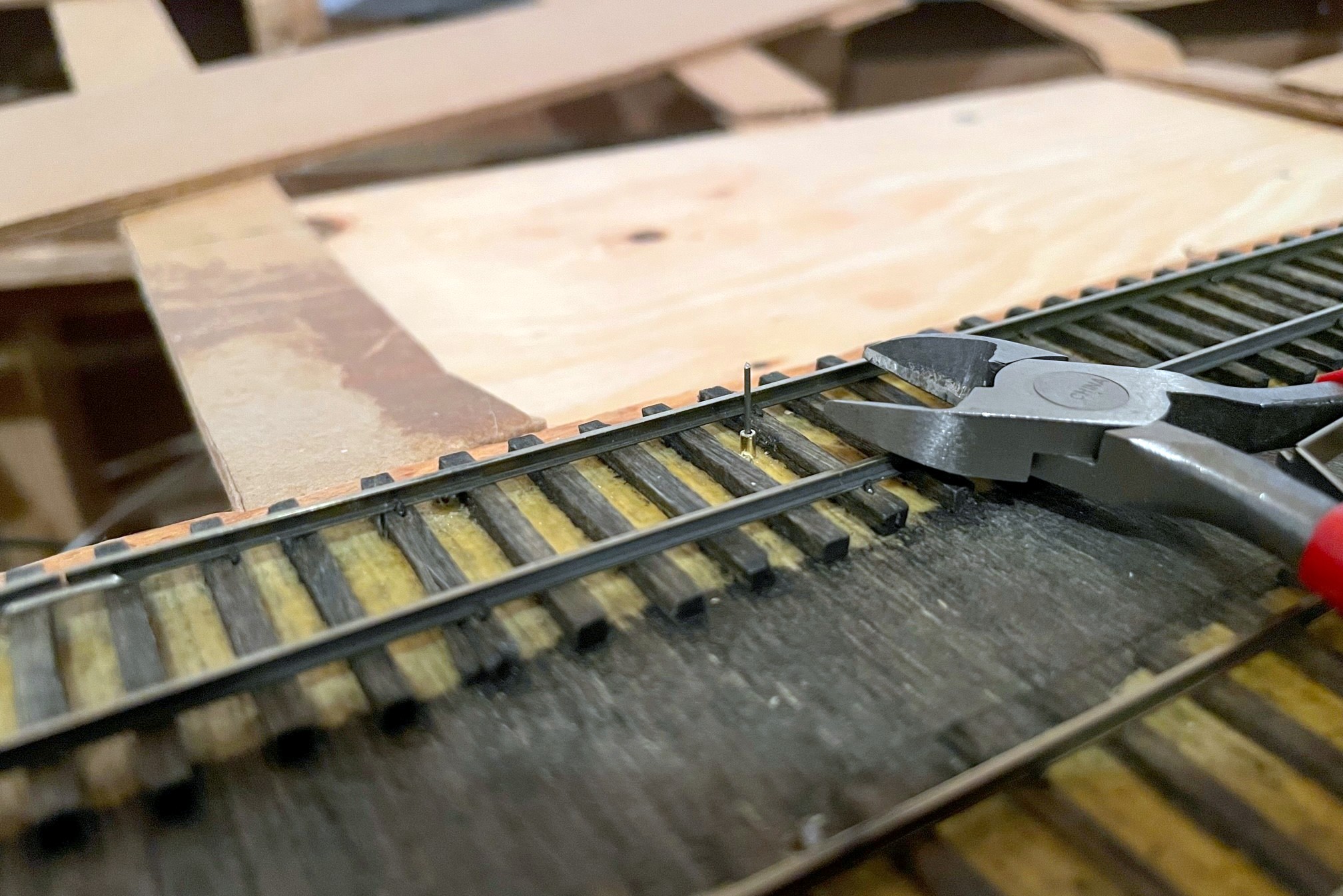
The brake wire should initially be longer than required in the recessed position
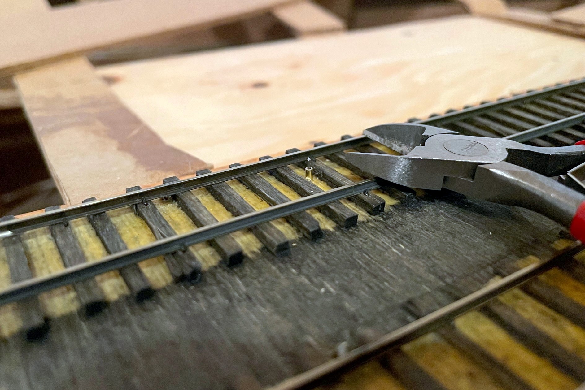
The final step is to trim the brake wire. I’ve found if I use a pair of wire cutters at rail-top level when the brake is in the DOWN (recessed) position, it is low enough for all my locomotives to clear and extends high enough to catch all my axles when needed. Because the wire’s location can be tough to see (especially when cars are over it), I use a little dab of yellow paint on the outside of the rail to indicate where the brake wire lives for easy spotting by crews.
The brake wire can be tough to see with cars on top of it, so I use a little dab of yellow paint on the rail to help operators know the brake location
I’ll also share some “lessons learned” for using this type of handbrake:
The brake will find your lowest-clearance locomotive and keep it from moving until you trim the brake wire–remember this locomotive and use it to test all brake installs
If you try to pull a string of cars when the brake is engaged, you WILL bowstring every car between the locomotive and the brake off the rails (sometimes violently)
If you leave the brake “up” and roll cars into it, they will bounce back quite jarringly upon hitting the brake
If you don’t pay attention and activate the brake under a truck bolster or low-hanging part of the car, you WILL raise the car off the rails and derail it (or topple it)
Other than these “gotchas,” I’m very happy with the operational possibilities these handbrakes add to the model railroad!
The St Charles Switcher crew sets the handbrakes to leave a string of loaded hoppers on the grade while working the yard
The first step of the handbrake is to locate where you want the brake, drill a hole, and insert a brass rod sleeve for the brake wire
Here’s the completed brake assembly with three pieces of wood, DPDT slide switch, brake wire (vertical), and control rod (horizontal)
The left is the front side of the assembly that will face the fascia–note the brass rod sleeve in the wood where the rod goes through
Top view of the handbrake assembly–the top board helps to mount the assembly securely under the subroadbed
Here’s the handbrake mechanism installed under the layout–the control assembly should orient to the fascia and not the track
The control rod should protrude through the fascia at least 2″
With the brake in the RECESSED position, bend the control rod parallel to the ground
I use a wooden axle for the control rod and drill out a hole the size of the control rod along with a notch on one side
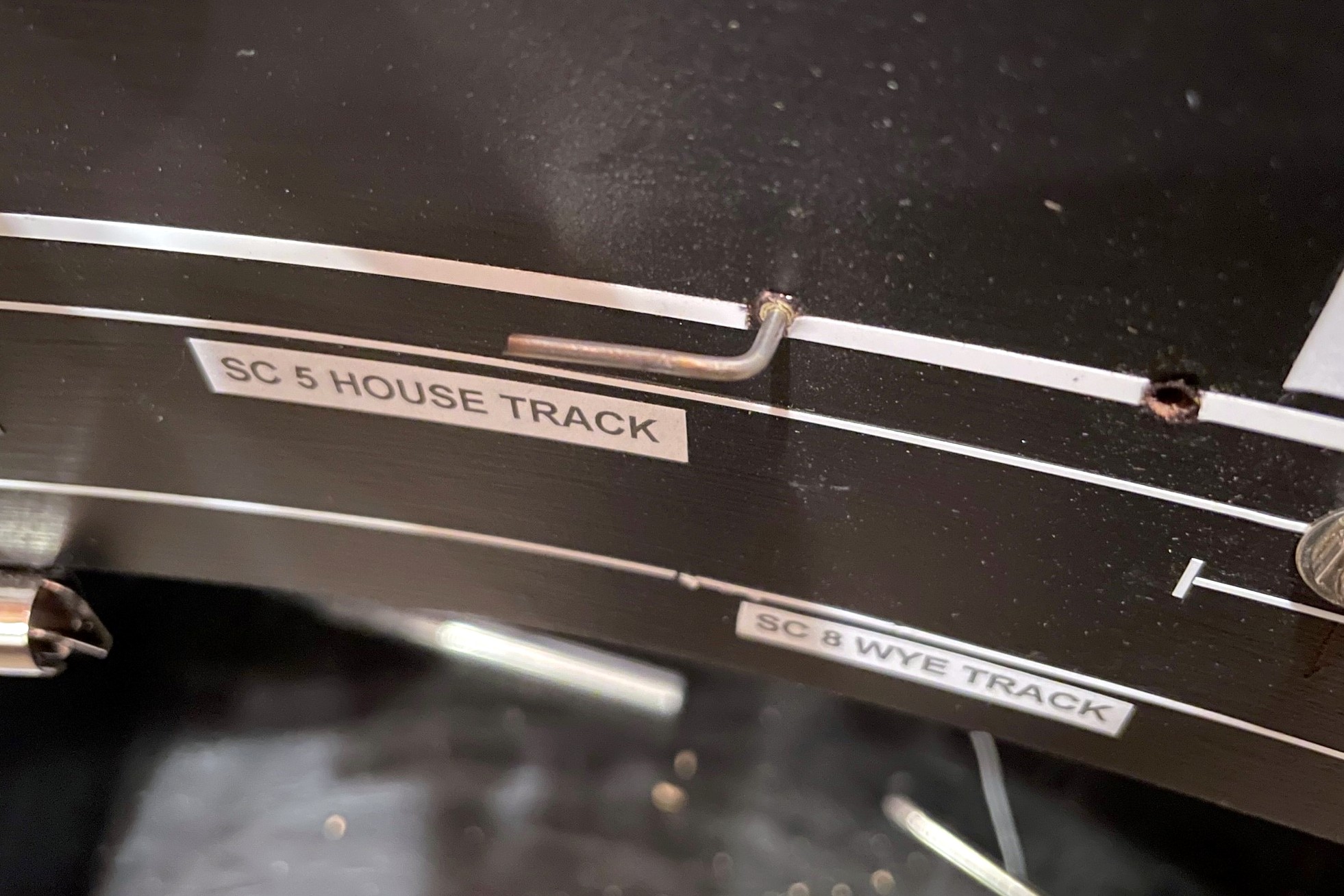
Here’s the finished control in the “off” position (in line with track)
Here’s the handbrake control in the “on” position–the LED helps alert operators that the track is not clear
The brake wire should initially be longer than required in the recessed position
With the brake wire in the recessed position, trim it to just above rail height with wire cutters
The brake wire can be tough to see with cars on top of it, so I use a little dab of yellow paint on the rail to help operators know the brake location
Here’s another handbrake on the main at a location where crews have to leave their train to work cuts of cars through a short run-around just ahead
Here’s another handbrake on a 3 percent grade above St Charles Yard–I use this one to set cars above the yard and use gravity to route them down the right track, just like the prototype would often do