Sometimes progress on a layout is painfully slow, especially for those in a stage of life with kids at home and full-time work. Time working on the layout comes in fits and starts as it takes a back seat (as it should) to other more important priorities. It can be discouraging to look at the accomplishments of a single evening or even a week and say “wow, I only laid three feet of new rail…” or “wow, all I accomplished was new Kadee couplers and cut bars on two hoppers…” I’m certainly not breaking any new philosophical ground here, but to really see progress, it’s important to look further back and see how far we’ve come.
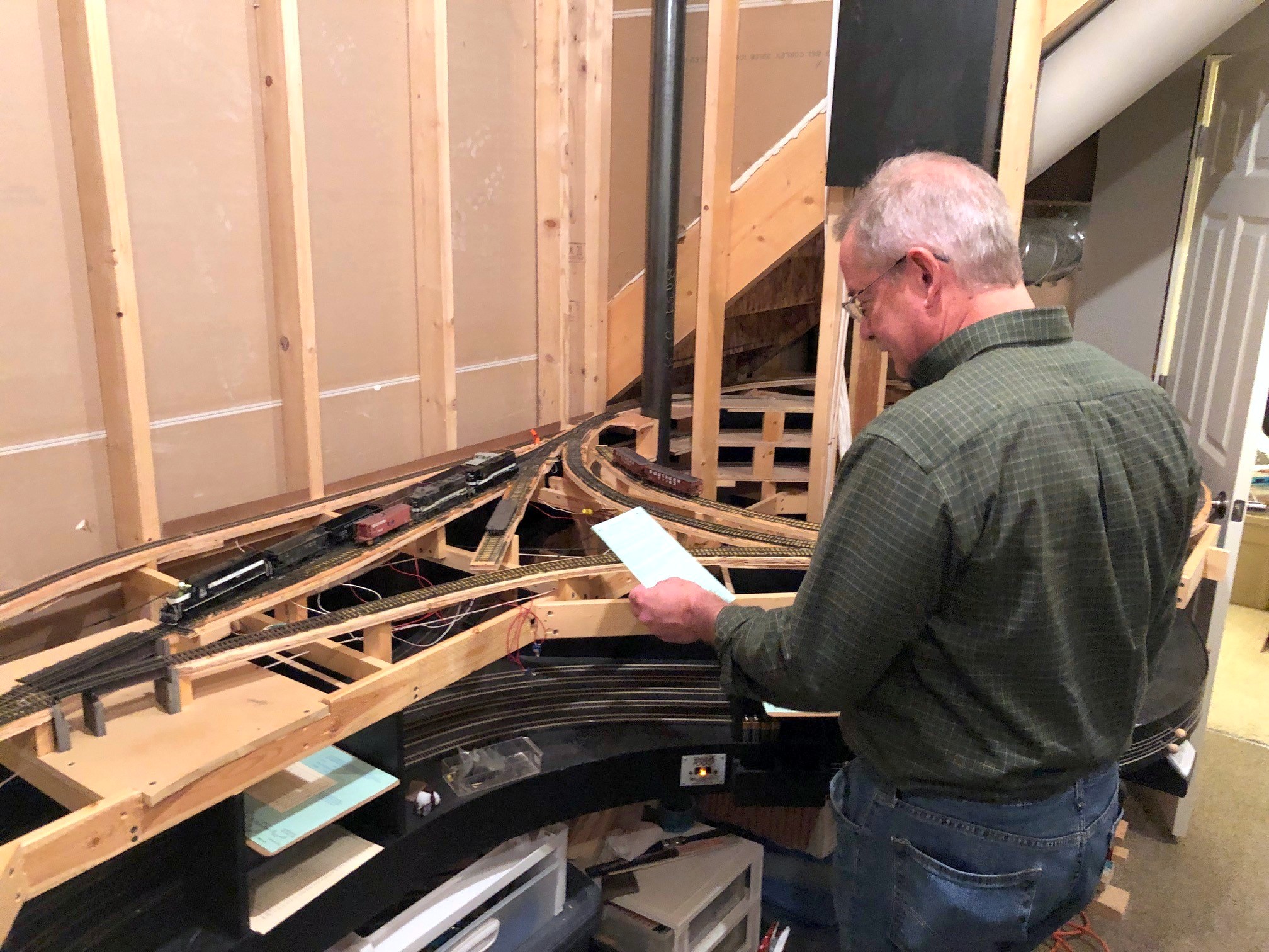
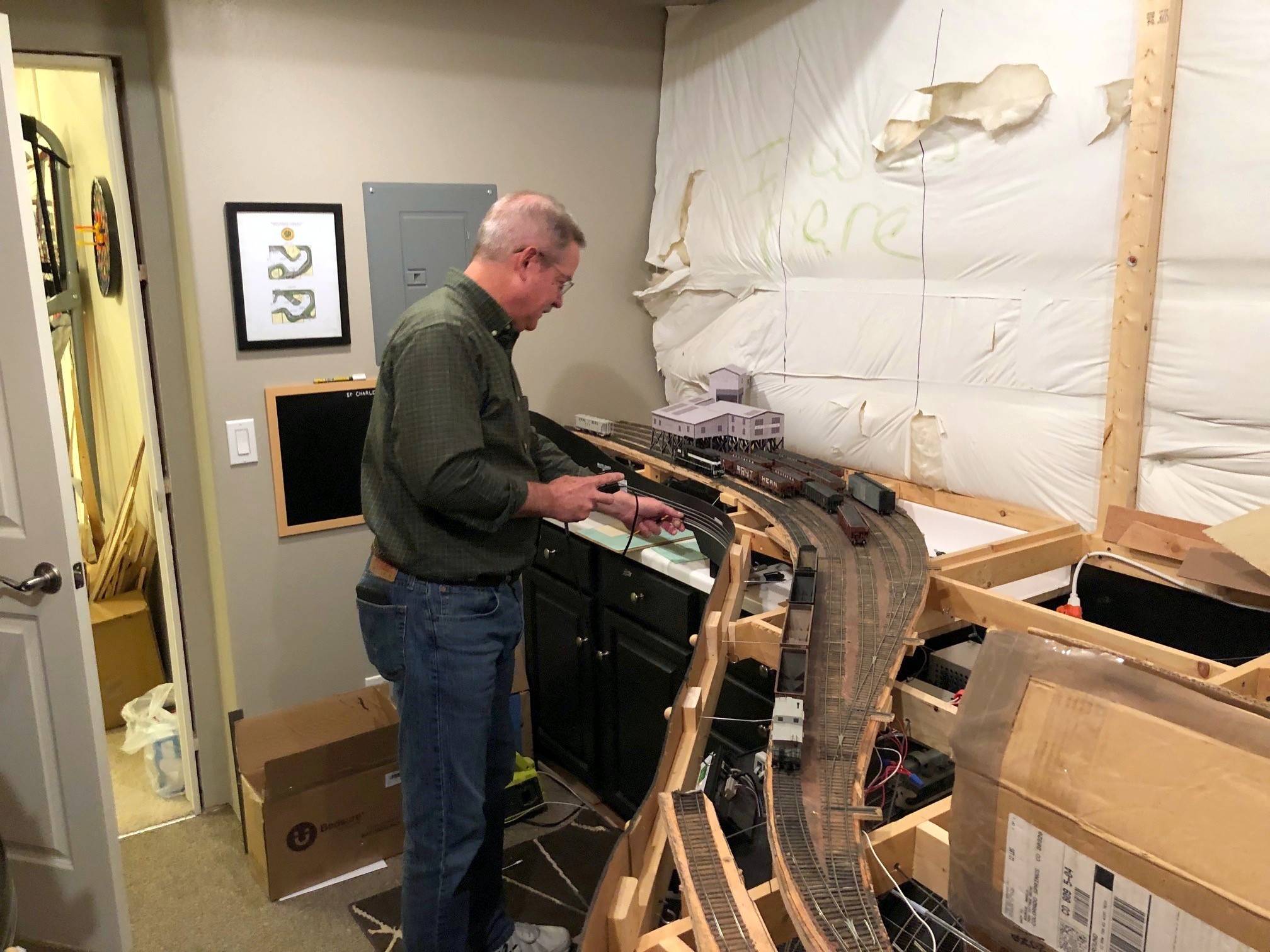
First multi-train operating session in December 2021
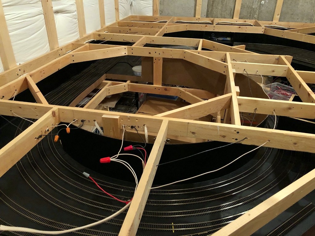
While 2021 will be etched in my brain as “Year of the COVID – Part 2,” it will also go down as a significant year in the life of the St Charles Branch with many important milestones. When the year started, the layout was essentially a staging level, a helix, and a lot of benchwork for the main level–not a single rail had been laid on what will eventually become the part of the layout with scenery. By the end of the year, I had the first real operating session with multiple trains and all the paperwork. Here are some specific milestones:
All the rails on the lower level complete (not an insignificant milestone for 100% hand-laid track)
First “scenic” elements on layout (Bailey’s Trace bridges for St Charles wye)
Several locomotives completed (F3A, GP7, GP35, GP38AC)
Several unique hoppers completed (CofGa short-taper offset, INT “hand-me-down”, SOU 100T “articulated” hopper)
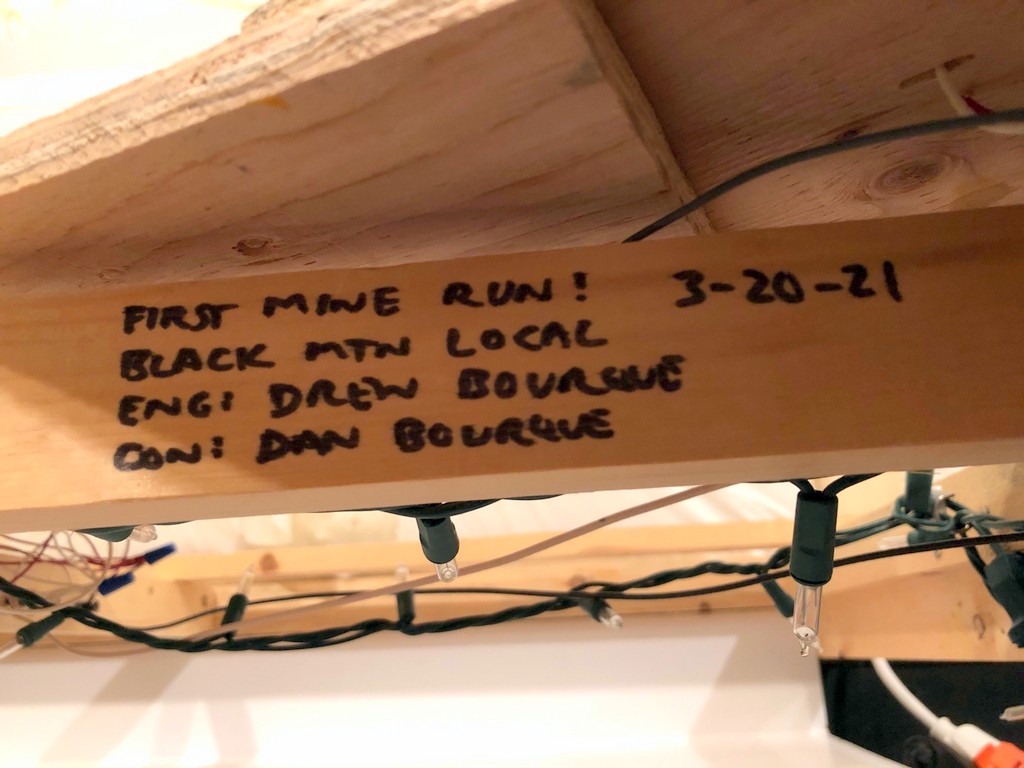
First mine run (Drew and Dan Bourque – Mayflower tipple)
First multi-train operating session (Patrick Tillery and Dan Bourque)
Like reflection on progress, goals for the future are also important. While the layout will always take a back seat to other priorities, here are the things I hope to accomplish in 2022:
Complete main helix between lower and upper level
Complete and paint lower-level backdrops
Finish benchwork for upper level
Build basic terrain for lower level
Lay track for at least one tipple on upper level
Have at least 3 more operating sessions to include first train to upper level
We’ll see at the end of 2022 how I did at meeting these goals. Even if I don’t complete them all, it’ll still be fun–Happy New Year!!!
Patrick Tillery stops at the St Charles depot while running the first-ever L&N CV Local
I’d like to thank Patrick Tillery for informing we he was coming over Monday night to check out progress on the layout which became the catalyst for the first multi-train operating session on the St Charles Branch! Despite some major obstacles such as having to reach under or across the layout to throw switches and a couple turnouts and cars that were acting up under their first real use, we managed to run 3 trains: the St Charles Local, the St Charles Switcher, and the L&N’s CV Local. These are the three primary trains on the layout during “busy times” across all eras of the layout–the timing of the trains may vary, but each serves the same basic function.
The St Charles Local is a scheduled train that runs between Appalachia/Andover, VA and St Charles. In leaner times, it serves as the mine run for the St Charles area branches. In heavier times, it serves to shuttle empty hoppers to the small “yard” at St Charles and pick up loads retrieved by the St Charles-based mine run. This is the “big train” on the layout and the only train to ever be assigned more than two locomotives.
The St Charles Switcher, known in some eras at the Black Mountain Local, is the mine run based out of St Charles that serves the area loaders. It picks up empties dropped off by the St Charles Local and plies the numerous branches and tipples dropping off empties and picking up loads. This train is the star of operations on the layout and the only train that will normally have a crew of two (conductor and engineer).
L&N CV Local runs around its empties at Mayflower with Patrick at the controls–the C420 is still in TC colors
The L&N Cumberland Valley (CV) Local is the only other scheduled train on the layout. This train works the old L&N mainline between Corbin, KY and Appalachia, VA including the modest coal loadings of the Middlesboro, KY area mines and the St Charles Branch. The L&N has trackage rights over the portion of the St Charles Branch from L&N Junction (Pocket), VA to the ends of the branches beyond St Charles which it reached via a short L&N branch between Pocket, VA and the L&N’s CV mainline at Pennington, VA. Despite several loaders in this area, the prototype CV Local never seemed to need more than a single locomotive, an RS3 or a C420, to handle the handful of hopper loads bound for the L&N.
Last night’s operating session took about 2 real hours. Patrick took the first train, the L&N CV Local, up to Mayflower to swap out 4 empties for 5 loads. Leading the train was Alco C420 400 still in Tennessee Central colors (it’s bound for the paint shop soon, but the L&N used ex-TC C420s on this line because they were the lightest on the railroad). The CV Local had to first stop at the depot track on St Charles wye to pick up an extra set of orders from the Southern dispatcher. This job took about 40 minutes from start to finish. After the L&N CV Local cleared St Charles, the St Charles Switcher with me as engineer showed up with 18 cars – 16 empties, a covered hopper of fertilizer for Mayflower, and a boxcar for the team track at St Charles. It took about 20 minutes to assemble the loads from the previous day and replace them with the fresh cars in the tiny 3-track yard. A derailment kept the L&N CV Local waiting for a few minutes until the superior train on the timetable was finally able to depart for Appalachia.
With the home rails now to itself, the St Charles Switcher left the house track next to the depot to serve four tipples with Patrick as engineer and me as conductor. We worked the two local tipples first, JAD Turner and Cavalier, before swapping out the boxcar for a now empty flat on the team track. With the locals taken care of, we swapped roles and picked up the remaining empties an the load of fertilizer and headed up the branch to Mayflower. At Mayflower, it took two sets of run-around moves to place the empties above the tipple and swap out covered hoppers on the tail track. One more run-around set us up to work the stub track at Baker before assembling all the loads and departing town. A little blocking back at St Charles yard rounded out the job which took nearly an hour.
All told, we got 2 hours of operations out of just 1/2 the layout–not bad! Despite working out a few kinks in the rolling stock and trackwork, the overall track arrangements worked well for the jobs–they required enough moves to keep operators thinking and having to make smart moves without being frustrating for lack of sufficient track. I underestimated how handy it is to have a wye for turning trains working the yard instead of having to run around the length of the train. It was also the first major use of paperwork on the layout, something I’ll describe in more detail in a future article.
I’m so glad Patrick was up to playing guinea pig for the first session, and I’ve now got a new punch list of stuff I need to fix before attempting this again. All part of the learning process!
L&N RS3 100 takes a trip around the wye at St CharlesCompleted St Charles yard tracks
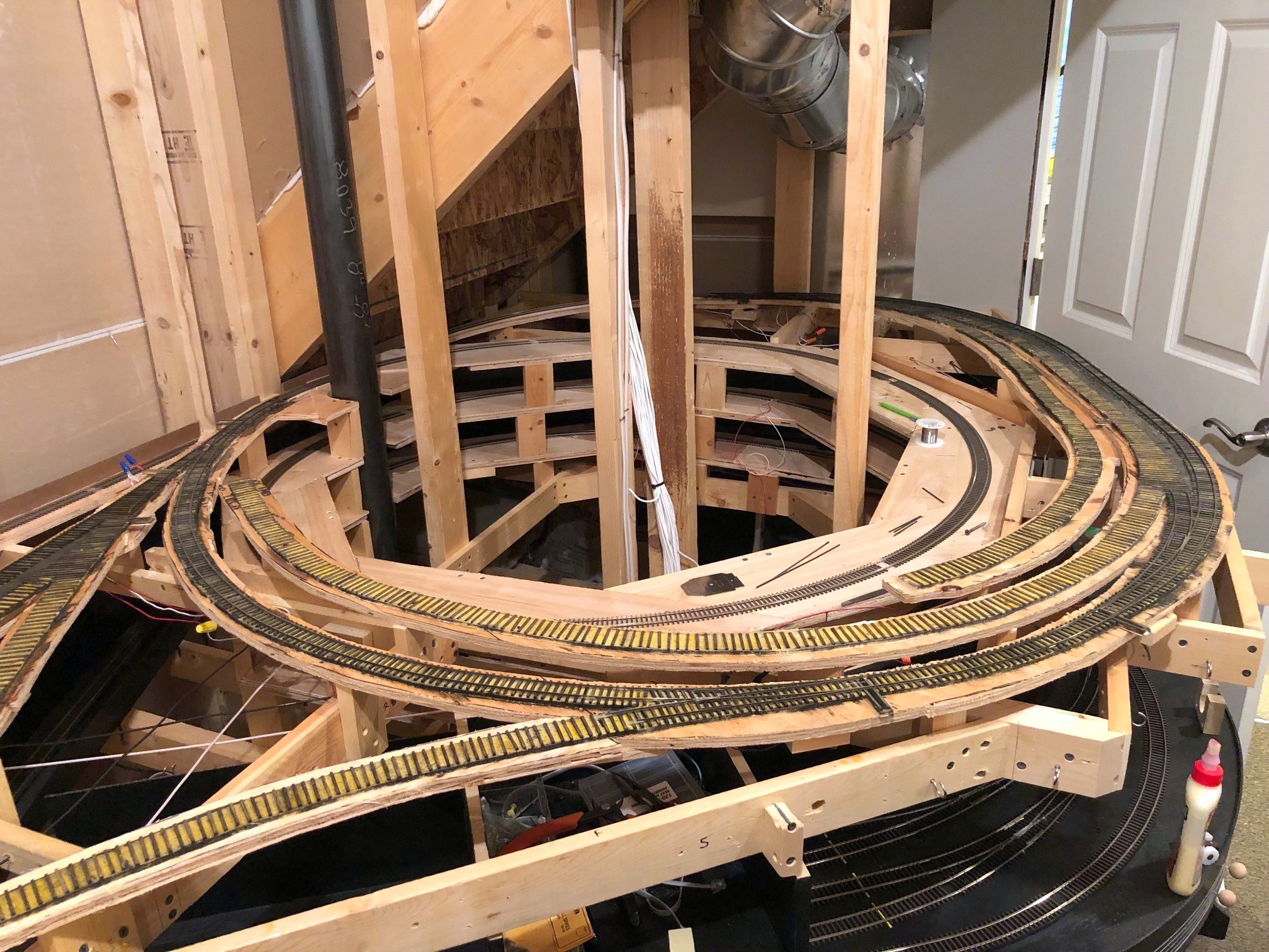
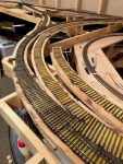
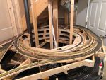
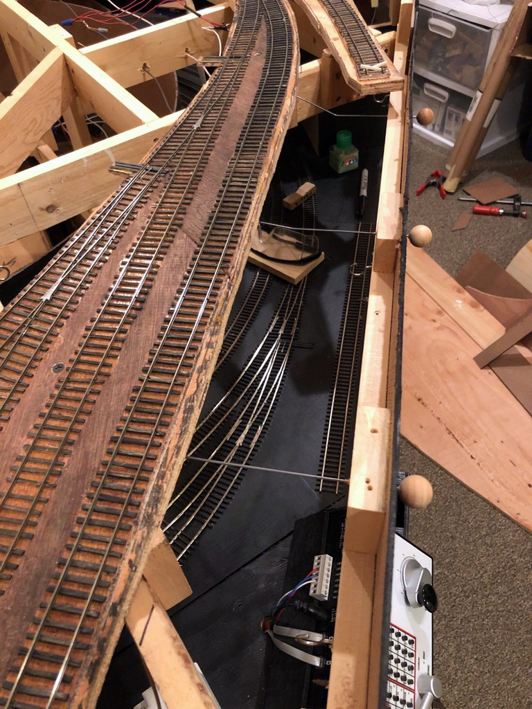
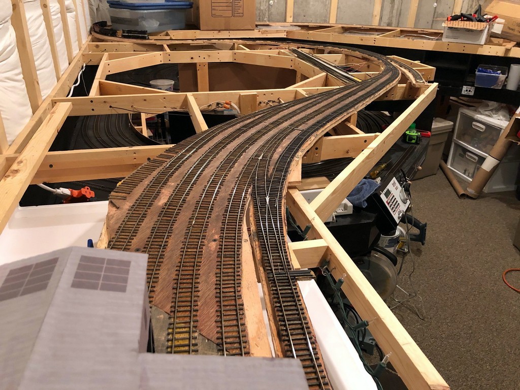
Hit a major milestone yesterday: the lower level tracks are complete! I completed the first scene, the end of the line at the Mayflower tipple, several months ago, and the last few months I’ve been working on the long scene at St Charles. St Charles – the branch’s namesake – was home to a wye, a depot, a couple small tipples, and a three-track “yard.” St Charles was also home to a mine run when the tipples were busy, so this is the central scene on the layout. All told, the St Charles scene is about 26 linear feet long and required 14 hand-laid switches (about 1/2 of them curved) and a couple of bridges.
Electrically, I made the entire Mayflower branch an auto-reversing zone for the wye. Can I just say the On-Guard AR solid-state DCC auto-reversers are awesome? The switching of polarity on the wye is absolutely seamless and unnoticeable–I highly recommend them! I also isolated a single rail of both the “house track” and “engine track” in the middle of the wye and will place a switch on the fascia. This will allow me to turn the power off to the two tracks that would hold idling power in case any sound locomotives get annoying. Next step is fascia and switch controls.
This is the current “end of track” just above the St Charles yard
L&N RS3 100 takes a trip around the wye at St Charles
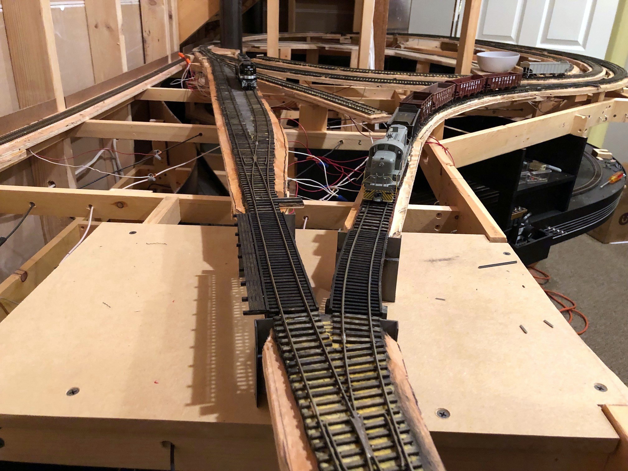
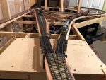
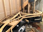
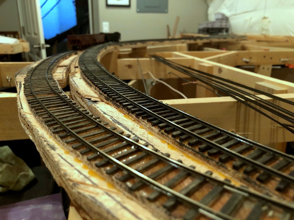
Overview of the Mayflower leg of the St Charles wye
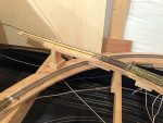
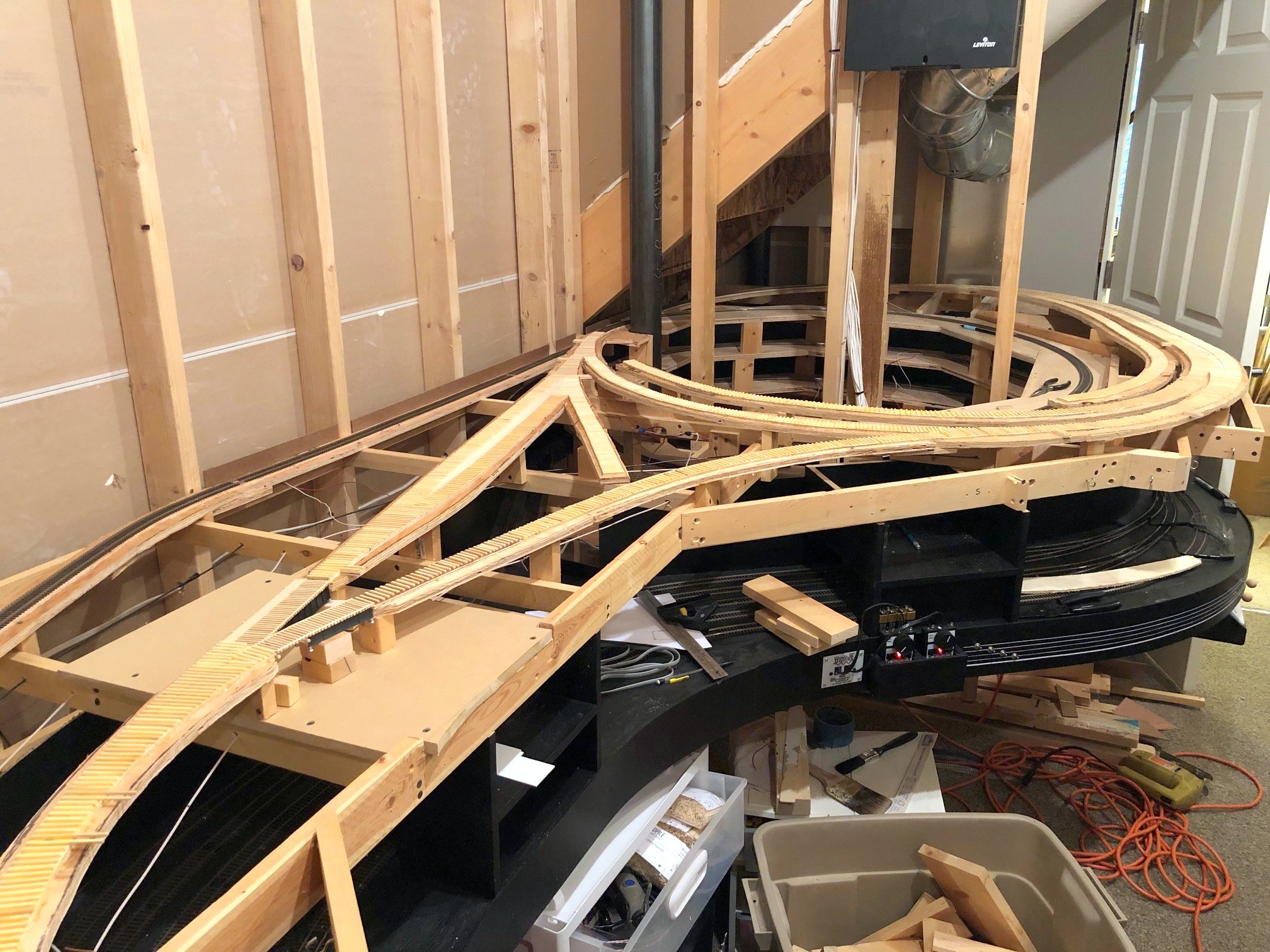
Celebrated something of a mini golden spike this week. I completed the mainline track for the Mayflower leg of the wye in St Charles. With this bit of track installed, trains can finally run up from the staging level and to a tipple (Mayflower). It’s not much in the grand scheme of things, but its a milestone nonetheless. Next will come the Monarch leg of the wye with its house track and engine track followed by the two yard tracks above the wye. Getting pretty close to having all the track on the main level installed.
I learned a good lesson on hand-laying track. The frog needs to be electrically isolated by cutting the rails on either side of the frog. To keep the frog and rails aligned, I spike both sides of the cut before cutting. When I wired everything up and applied track power the first time in this new section, it immediately shorted out. I could hear a soft click coming from one of the switches. Usually this means one to three things 1) I wired a feeder to the wrong bus, 2) my cut didn’t make it all the way through or 3) the point rails somehow slid back together with the frog. A check of all three of these things was good, but when I dropped the feeders from the point rails, the short cleared–it was still somewhere on this switch. After a few minutes of jiggling random things and staring at the problem, I finally figured out that two of the spikes that were holding separate point rails down near the frog cut were touching even though the rails weren’t. Go figure, metal spikes attached to metal rails conduct electricity… a quick repositioning of one of the offending spikes did the trick.
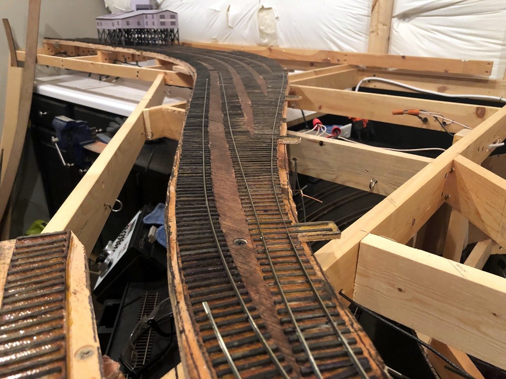
Track laying in progress on the Mayflower leg of the St Charles Wye
Overview of the Mayflower leg of the St Charles wye
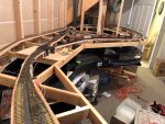
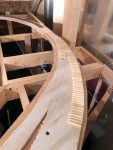
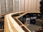
Overall view of the wye at St Charles including the house track and engine track inside the wye and the bridges over Bailey’s Trace
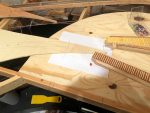
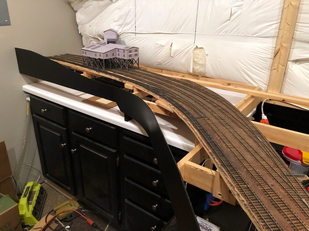
After a nice and productive summer focusing on building models (thank you St. Louis RPM meet for the motivation), I’ve returned to working on the layout. The next step is a big one, the scene of St. Charles, VA. This is the central scene of the entire layout. This is where trains emerge from staging, the site of the local station and engine tracks, the small yard for the branch, and the wye taking trains either up to Mayflower or Kemmergem, Monarch and Benedict. While I could have modeled these tracks in pieces, I decided to do the entire scene at once to avoid further stalling and to limit the need for multiple coats of stain on the ties (takes forever to clear out the smell!).
I’m using basic cookie cutter construction. I lay down 1/4″ door skin ply and draw out the tracks using templates and a piece of flextrack with thumbtacks to hold it in place. After cutting the upper subroadbed, I then trace the pattern only 1/2″ plywood staggering the seams. For this scene, I cut out all the 1/4″ ply to make sure everything fit, then cut the thicker ply. Construction so far is proceeding according to the plan, though I did make a modification to the track plan–instead of having the two small coal-loader tracks butting into one another, I reversed the siding on the wye to place the switch along the benchwork instead of in the back corner where it would be tough to reach. The prototype siding in this area appears to have been double-ended, so it’s not a big deal either way. As a bonus, the new arrangement allowed me to get a few more cars’ capacity on these sidings.
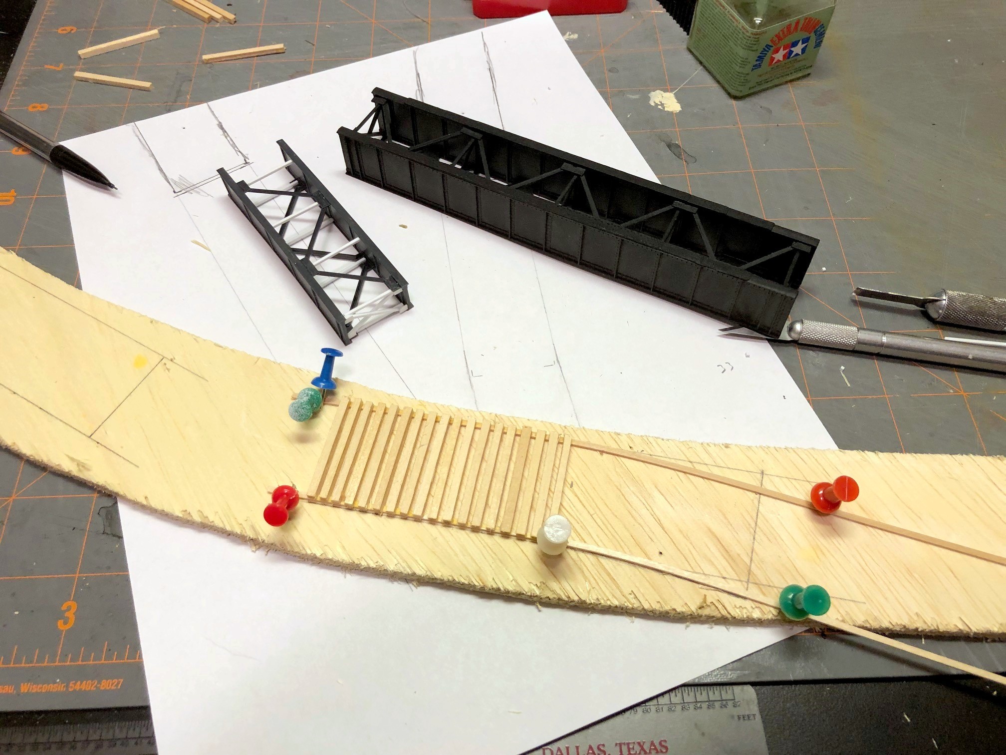
Laying bridge ties for the shorter bridge over Bailey’s Trace
The toughest part of this scene is the pair of bridges across Bailey’s Trace at one end of the wye. On the prototype, there was a plate girder bridge just over 50′ in length on the main, and a shorter plate girder bridge (about 25′) which adjoins a curved bridge portion which appears to have been joined with a short wooden trestle on the curved portion (it’s all been redone with ballasted decks now). I used a 50′ Micro Engineering bridge for one section and cut down a 30′ ME bridge by one section on the other. I hand-laid the bridge ties using a template I drew up on a piece of paper. Next will come the concrete supports so I can attach the bridges and lay the rails across.
It’s encouraging to see progress in the layout room again, and I will definitely have my work cut out for me between now and Christmas hand-laying 14 switches!
First ties laid for the St Charles scene, a 24″R and 30″R curved turnout
Overall view of the wye at St Charles including the house track and engine track inside the wye and the bridges over Bailey’s Trace
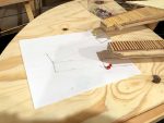
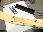
I drew in the bridge locations on a piece of paper
Drawing in the next subroadbed using the paper bridge template
Laying bridge ties for the shorter bridge over Bailey’s Trace
This is the future St Charles yard, just two long tracks on either side of the main
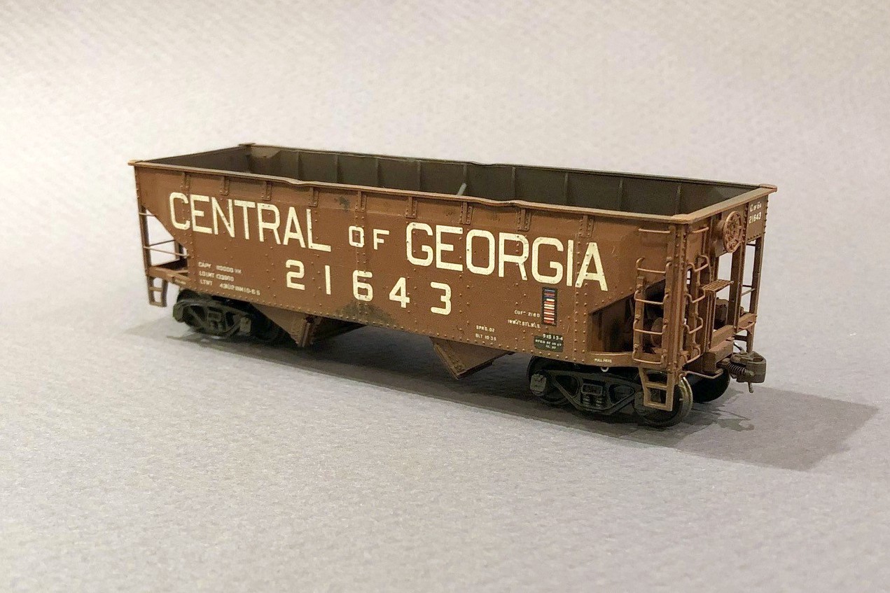
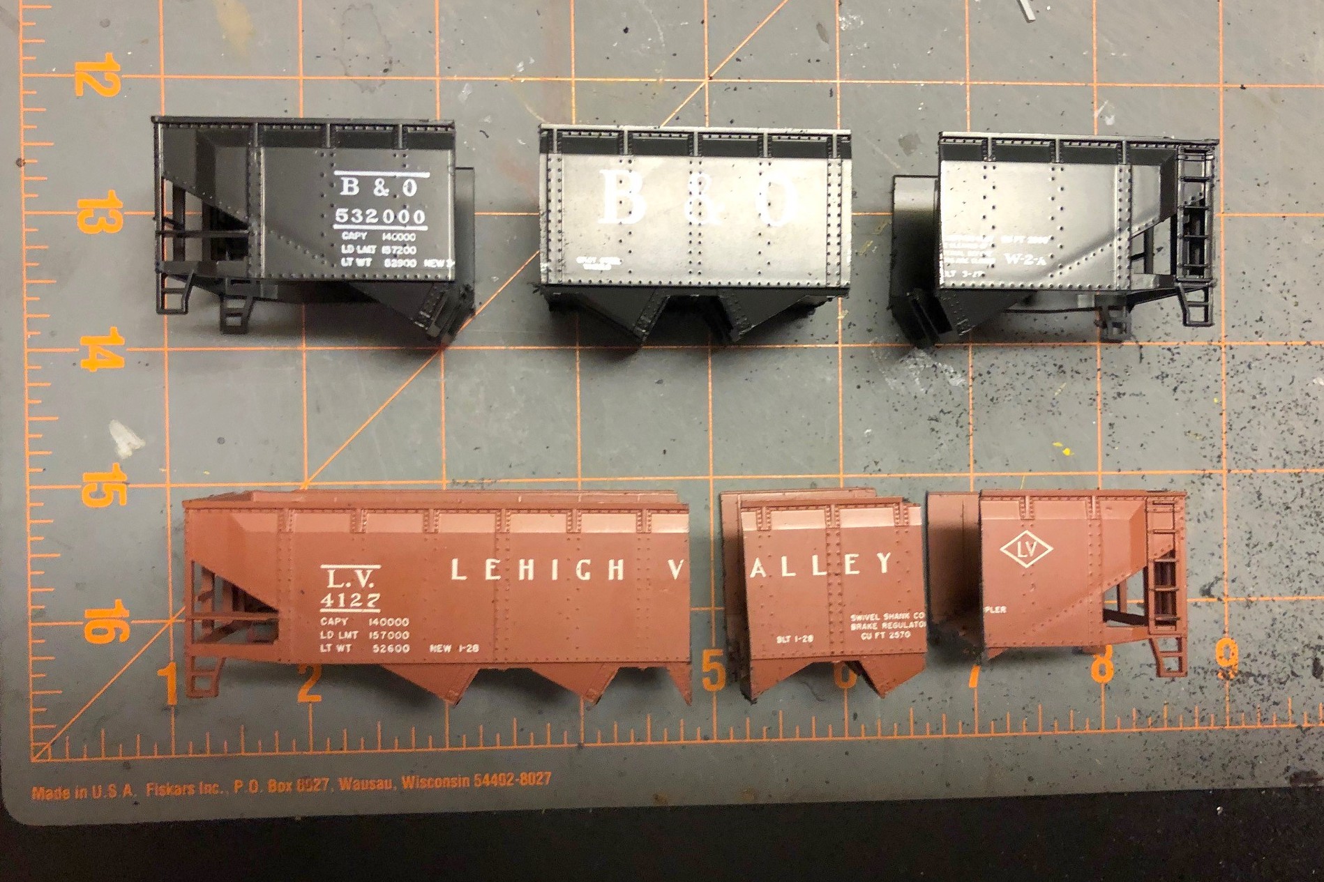
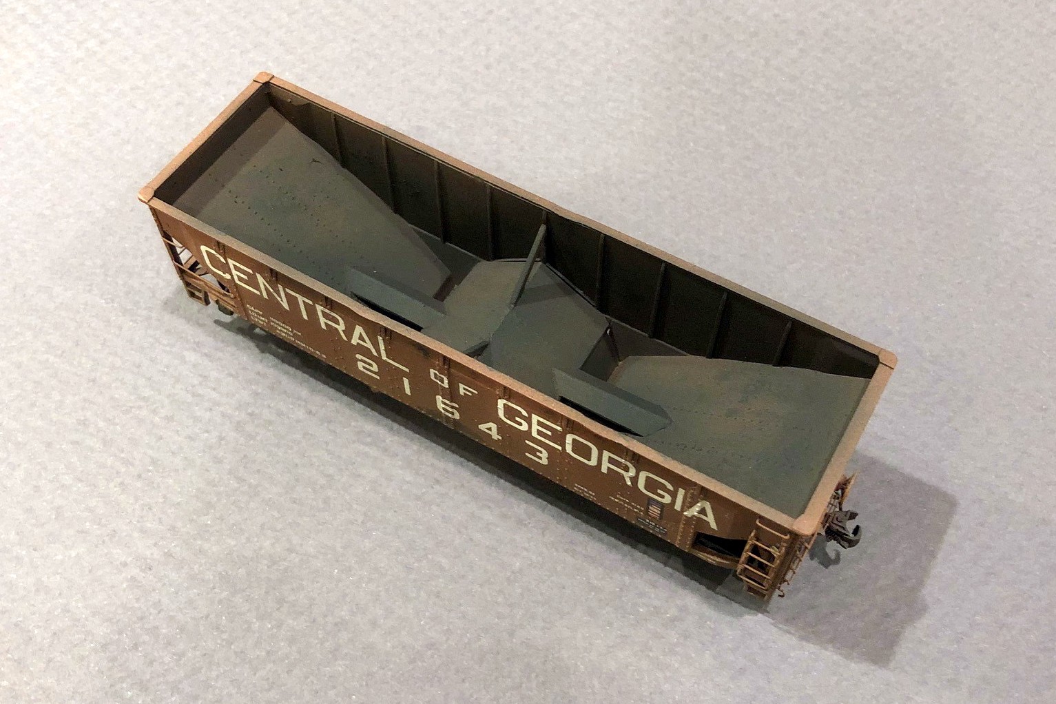
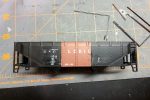
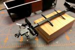
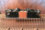
I’d had my eye on this project since the first time I saw a picture of one of these cars online. There were two challenges that held me back. First, no one made the right decals. Secondly, no one makes this car, so it would be a pretty major kitbash. It’ sat on the “someday” list until K4 Decals produced a set of good looking decals. The main excuse was now out-the-window, so I had to bite the bullet and figure out how to kitbash the car. The challenge is the shallower and steeper offset angles–they’re very distinctive and different from the angles on common twin hoppers like the old Athearn and newer Atlas models. The only thing that looked close were the angles on the old Athearn blue box quad hopper. I had one sitting on the shelf, so I took a closer look. It turns out the angles are perfect, as are the rivet strips and rivet patterns along the ribs. So, how to turn a quad hopper into a twin.
Cutting down a quad hopper to make a twin sounds pretty straightforward. If you don’t care about having an extra rivet strip, it is! Of course, I had to care… sigh. There’s an extra rib between the rivet strips on the twin compared to the quad, so I had to figure out how to get the extra rib in there. Turns out, there’s just no way to do it with a single shell (or I wasn’t smart enough to figure it out), but it was possible using two shells–2 quad shells to make a 1 twin… makes sense. I guess technically I could make 2 twins with 3 shells, so I did keep the extra pieces in case the bug strikes again.
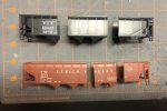
2. Cut hopper bodies
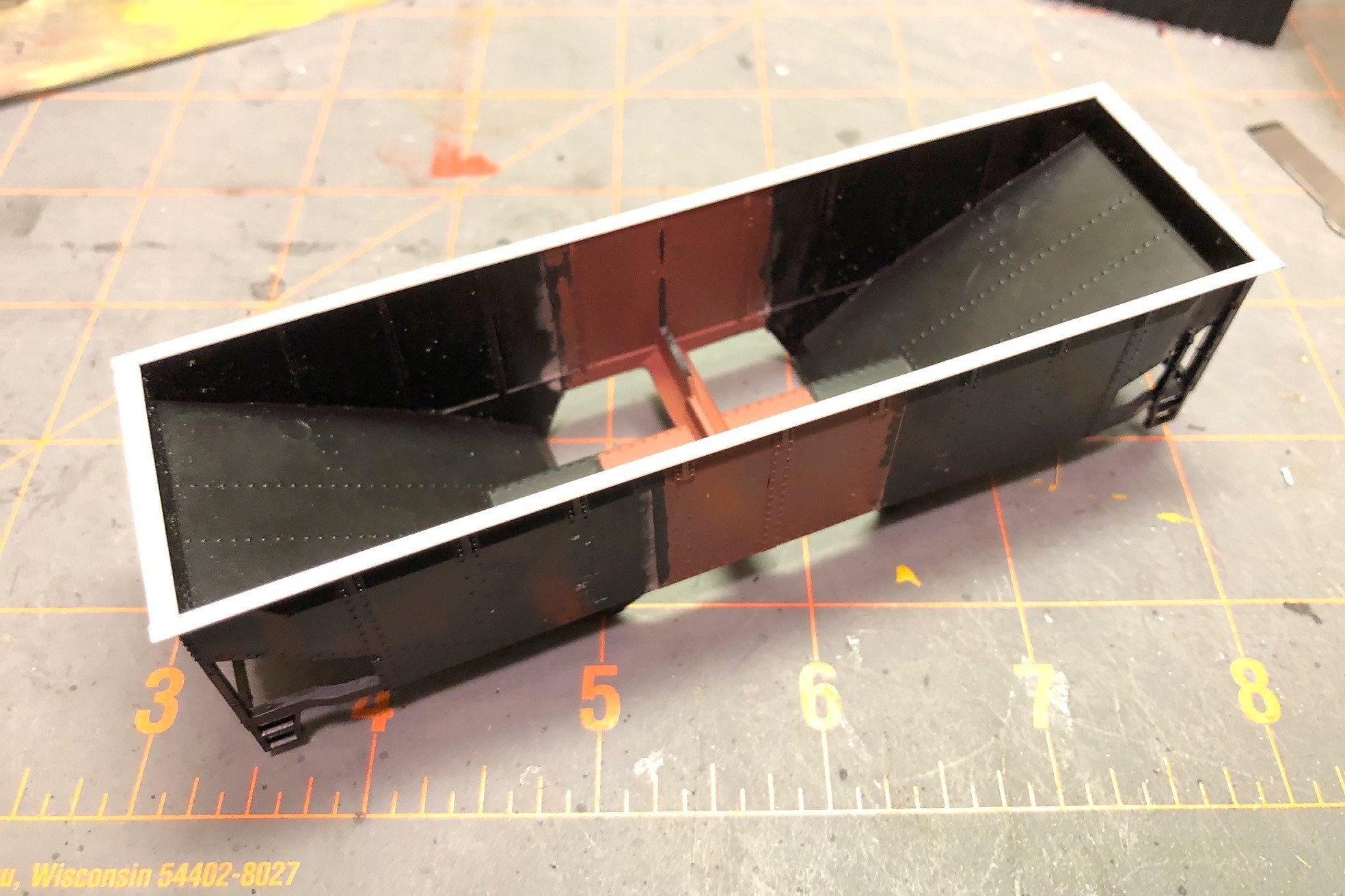
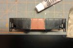
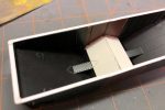
Picture 1 in the gallery shows the two original shells, and you can make out the pencil lines where the cuts need to be. I chose a spot between rivets to give myself a chance of saving the rivet detail in the putty and sanding step later. Using a razor saw, I cut each shell into three pieces as seen in picture 2 with the black hopper providing the ends and the red hopper providing the center. After cleaning the bays off what would become the center, I glued the ends to the new center piece as shown in picture 3. This step is the most critical of the whole project, and it took some filing to get everything square. I used plastic model cement to give myself time to line up the pieces–it’s crucial to get the sides aligned so they’re “level” across the gap. A gap is easy to fill and sand flat, but only if the sides are even with one another.
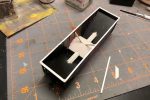
Once this new shell had dried thoroughly, I removed the top chord. The top chord on the original model is pretty chunky, and it would be easier to add a new one across the gap than try to fill every gap on top perfectly. It was pretty simple using a No 11 X-Acto blade swiped repeatedly under the top chord resulting in the shell seen in picture 4. Next, I filled the gaps with modeler’s putty. Using a combination of the back of an X-Acto blade and fine sandpaper, I was able to get the joint pretty smooth, and I was careful to stay away from the rivets as you can see in picture 5. This was also a good time to remove all the molded-on grabs with a combination of nippers and X-Acto blades. I found the corner posts and ladder posts to be really thick, so I whittled them down a little on the back side with an X-Acto. I also trimmed the top of the bottom sill near the ends to make it a consistent thickness instead of a taper like the model.
7. New styrene top chord
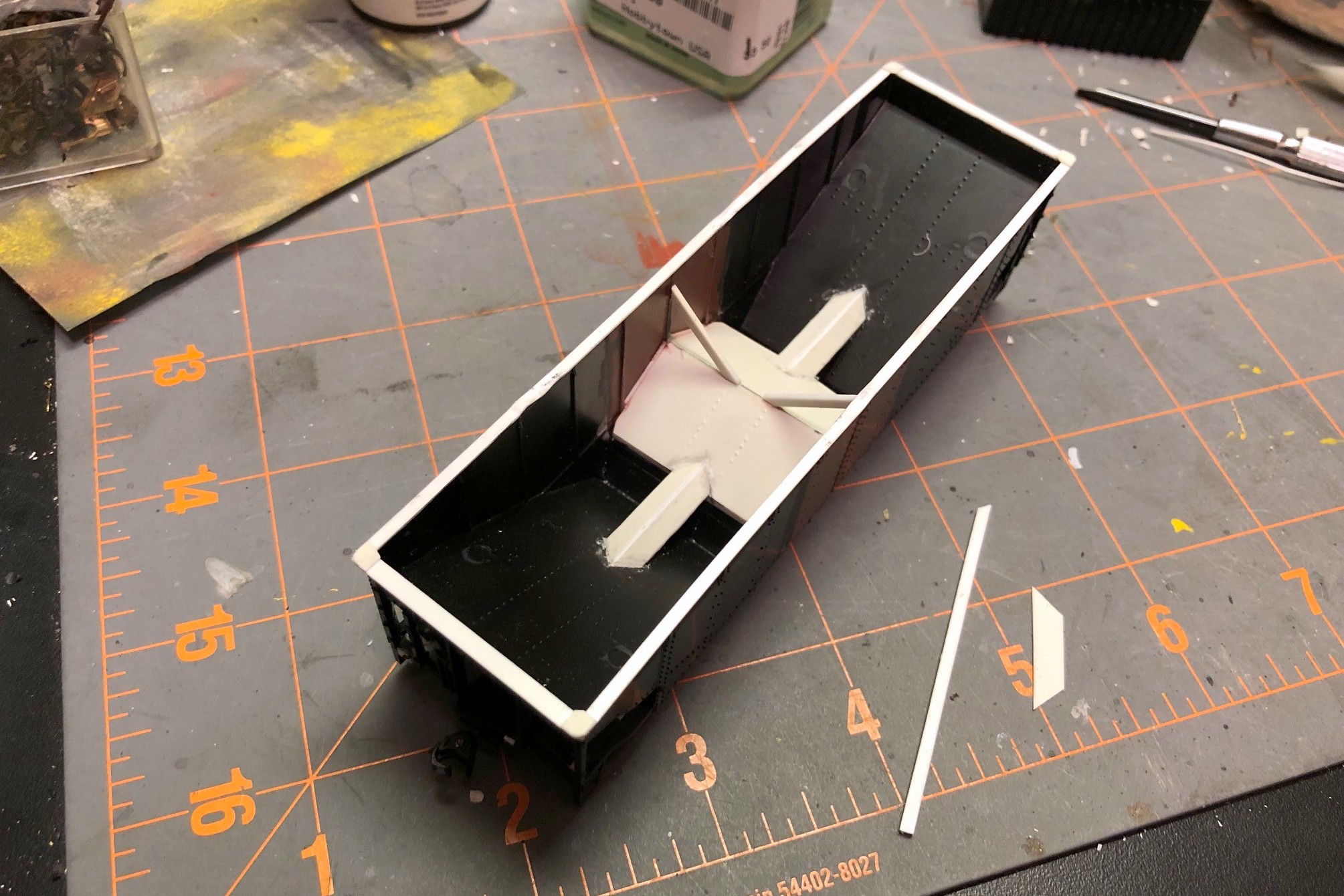
Next I worked on the center sill and undersides. First I cut the center out of a single underbody to shorten it to the right length and joined the ends together with glue. After it set, I used a large X-Acto chisel blade to remove some the material as shown in picture 6. I left a little strip to hold the hopper doors on. Next, I added a new top chord to the shell. I didn’t have the bag to verify, but I believe I used Evergreen HO scale 2×6 for the sides and 2×8 for the end to get to picture 7. I added four corner caps made from .010″ sheet styrene and rounded them on the top and on the corner after they dried using a file. Moving back to the underbody, I removed the existing mounting “blobs” for the brake gear, and in their place, I added angles from the bolster area to the corners using strip styrene (this was a pain, but I found if I cut them to the approximate shape, glued them with plastic cement, then press fit the underbody onto the shell and maneuvered the angles into position while the glue was still wet (I didn’t glue the underbody to the shell yet). When the angles had set, I added the brake parts including some brass wire for piping and a bracket for the reservoir made from sheet styrene as shown in picture 8.
10. Finished interior
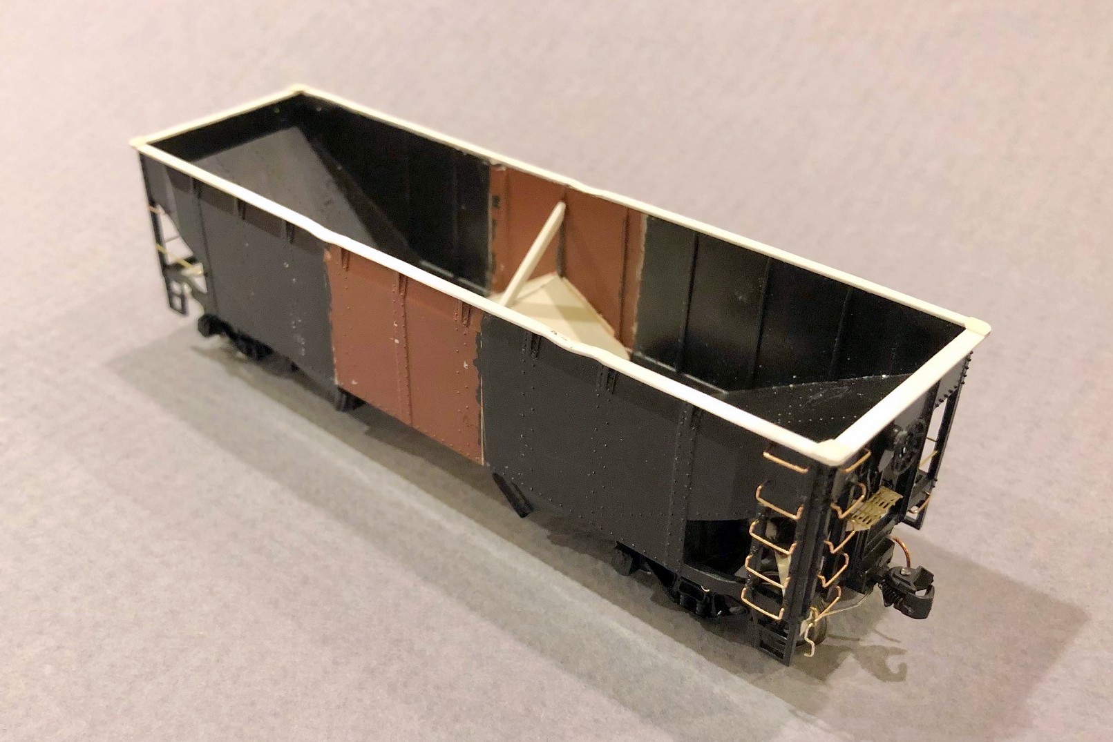
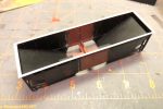
The interior of the car was challenging. I went ahead and glued the underbody and doors in place first, then added some styrene square rod above the doors to get it even with the model’s center sill piece. The new center slope sheets were cut from a single piece of styrene, and I used a pounce wheel to put some rivet lines into it to match the end slope sheets. Because of the ribs, the new slope sheet didn’t quite reach the sides, so I used bits of styrene to fill in the gap between ribs as seen in picture 9. Next came the not-so-fun part of turning the flat center sill ridge inside the car into a tapered one. I don’t have interior photos of one of these cars, but I can’t imagine using a flat top when you want the coal to exit the car. This step was not fun. Not one bit. Lot’s of measuring, cutting, folding, and taking back out and cutting again. My pieces ended up being too wide, but I just glued them on, let them set, then trimmed them to the width of the ridge in the shell with an X-Acto blade. Some styrene strips to make the angle braces and the interior was complete as seen in picture 10.
11. Final details added
Now I was ready for all the little details that you can see in picture 11. I drilled holes and installed all the grabs, making the long grabs on the non-ladder side from brass wire. I added coupler cut bars to a bracket made from styrene and an eye bolt. I made tow loops from brass wire, and I made a new brake platform from bits of styrene and some brass Apex roof walk material. I added the brake line along one side using brass wire and eye bolts. I added some tack boards from styrene on the bottom sill. I added train line hoses made from copper wire from old Cat 5 cable glued between two styrene angle bits (makes for an indestructible train line). A kept the molded on steps as I needed them to be durable for layout handling, but I used an X-Acto blade to shave them down a bit in the back to thin them out. Finally, I added a little buckling to the top chord using a 100W lightbulb held to the styrene for a few seconds and then pushed down using the handle of an X-Acto knife (be careful, the styrene melts really quickly). It was finally ready for paint (picture 12).
16. Final hopper – interior weathering
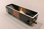
I first sprayed everything black, then gave it a couple coats of “burnt sienna” for the boxcar red. Because the paint was very flat, I sprayed it with a couple coats of Testors Glosscoat (rattle can) to prep it for decals. The K4 decals worked really well and had just about everything needed with the exception of an ACI label I stole from a Microscale data set. The K4 set looks like it’s designed for a 33′ car, and this prototype is a 34′ car. I ended up cutting the road name into “CENTRAL,” “OF” and “GEORGIA.” I place the end lettering first and then centered the “OF” between them, a little more spaced out than the decal sheet. I used about 800 applications of Micro Sol and Micro Set and pushed the decal firmly onto the body using a damp paper towel until everything was nice and snug over the rivets and on the body as seen in picture 13.
Weathering was a three step process. First, I dry brushed a little dark rust color both inside the hopper and in a few spots on the outside using a picture of this specific car as a guide. Next I gave it a couple of washes with very thinned black and then tan paint, wiping it off down the car (like rain streaks). Finally, I airbrushed some black inside the hopper and underneath followed by a couple coats of tan, hitting the trucks and hopper bays harder than the body to get the final model shown in pictures 14-17.
I’m very happy with how this project turned out, but I’m also very happy I don’t need a fleet of these cars. Many will look at this car on the layout as “just another offset hopper,” but I’ll always know the extra work that went into building a more accurate model of a neat prototype.
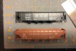
1. The two Athearn quad shells with pencil lines where the cuts will be made
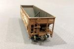
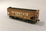
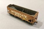
Interstate hand-me-down hopper in transloader service
Added another hopper to the roster today. This car is one of the hand-me-down hoppers given to the Interstate in the early ’60s when the INT was under Southern ownership but still operating independently. The independence didn’t stop the Southern from specifying a Southern-inspired paint scheme. This model started life as an Athearn blue box model–it was a hand-me-down from an old friend and mentor who got me into model railroading as a kid, so the body of this car must be 40 years old! The toughest part of this model was modifying the angular peaked ends to the oval version seen here. The cars in this series were a hodgepodge with various ends, so photos are helpful. Other details include DA steps, tichy grabs, and some homemade tow loops. The decals came from K4 Decals, and the unit received moderately heavy weathering to reflect its age and status as an end-of-life car.
After 1965 when the Southern consolidated its operations at the Interstate’s Andover Yard, most of these cars spent the rest of their lives in captive service between the Interstate and St Charles area mines and the Westmoreland Transloader that was build on top of the Southern’s old yard in Appalachia, VA. These cars became known as “yellow balls” because many of them had a large yellow circle painted on the side. This is actually my first time actually applying a “yellow ball” to a model hopper, and it’s definitely something I’ll duplicate in the future as it makes these cars very distinctive!
Interstate hand-me-down hopper in transloader service
Interstate hand-me-down hopper in transloader service
Finished car with some light black and tan airbrushing on the sides, trucks and interior
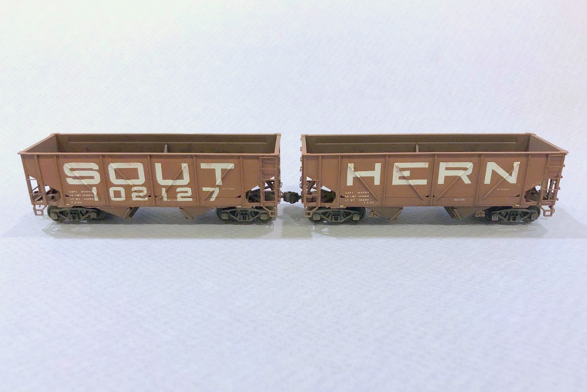
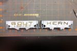
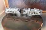
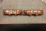
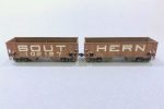
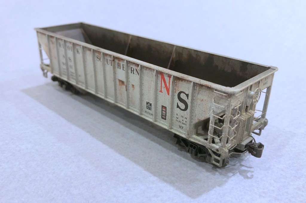
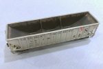
The Southern Railway was definitely known for innovation, especially in the ’60s. They were one of the first railroads to use large numbers of 100T hoppers for moving coal. The Southern still had a large number of usable 50T cars, particularly war emergency rebuilds and ex-Interstate hoppers, so they permanently paired some of them into what they deemed 100T “articulated hoppers.” There was nothing fancy about it, they just removed the coupler cut levers from between the cars, put the brake ends of each car at the ends, and numbered them as a single car. The idea was it allowed 100 tons of coal to be moved in a single car shipment for a customer which gave these old cars a little more life in the 100T era. There were several paint schemes used on these cars include a red version with “SOUTHERN” on the left-hand car and the car number on the right-hand car. Some cars had a black version of this. The most striking and unique cars were those painted with giant lettering and “SOUT” on one car and “HERN” on the other–this is the car I wanted to model.
The base cars were easy enough. They’re essentially stock Proto 2000 War Emergency hoppers with a couple minor modifications. I trimmed the tow loops off the bottom, added small beveled strips of styrene under the outermost ribs, and used bent .012″ wire to fashion new side-mounted tow loops above the styrene strips. I also used dummy couplers on the “A” ends of the cars that I pulled out of an Accurail 50T AAR hopper kit–this will keep operators from inadvertently uncoupling the car on the layout. I only added coupler cut bars to the “B” ends like the prototype, and I added a scratchbuilt train line air hose to each end (piece of bent copper wire from old Cat 5 cable sandwiched between two styrene L-shapes).
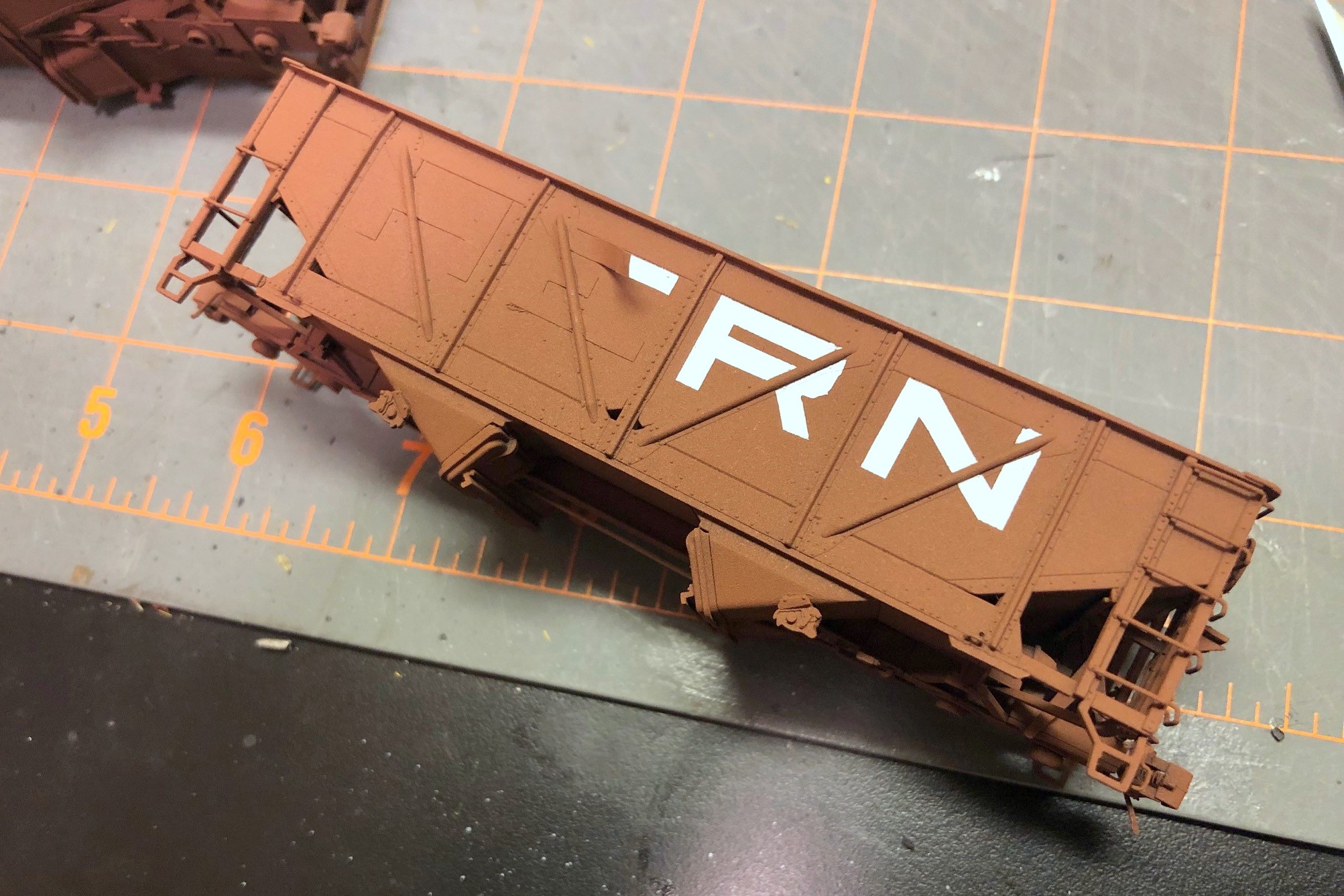
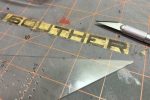
Step 4. Apply the lettering masks to the car, cutting around the ribs
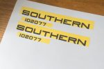
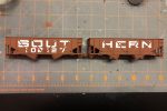
The tricky part of this model is the lettering. No one makes a lettering set that even comes close, so I would need to either make my own decals or somehow mask and paint the lettering–I opted for the latter technique. First, I had to draw up some artwork. I used my favorite graphics program, Microsoft PowerPoint, to create the lettering using large rectangles and quarter circles. Once it looked about right, I copied and pasted the lettering as an image (right click and picture icon) on a new sheet, then I was able to size it and print it with the letters 3′ tall in HO scale and the numbers 2′ tall. Then I covered the lettering with some Tamiya model masking tape and ran it through the printer again to get the ink onto the top of the tape. Warning: even after the ink dries, it still smears a bit, so I used another piece of plain masking tape to remove some of the ink, and I was careful not to get smudgy fingers on the car.
Speaking of the car, I airbrushed the sides white and let them dry overnight. Back to the lettering, I carefully peeled the tape off the paper and placed it on a clean cutting mat. Then I used a straightedge and Xacto blade to cut along all the straight edges. I freehanded the corners which was a bit more challenging. The angled ribs on this car required me to eyeball where the rib would go through the letter (I had a picture of an actual car), so for each rib I removed about 1/16″ of masking tape. Next, I peeled the letter mask off the cutting board and applied it lightly to the car, using a blade to lift and reposition it as needed. After all the lettering was in place, I used the round end of the Xacto handle to burnish the tape onto the sides securely.
Step 7. Carefully remove the masking using a sharp blade to get under the tape
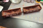
Back to the painting booth, I first sprayed the cars with black as a dark primer and then gave them a couple coats of oxide red and let them dry for an hour. After the paint was dry, I carefully removed the tape from the sides using a blade and careful fingers to reveal the white lettering. I thought I was going to have a lot of touch-up to do, but the tape held up very well and left mostly clean edges. With all the tape off, I then used a brush and white paint to fill in the lettering gaps across the ribs. I sprayed it with some gloss coat and applied the capacity stencils and other small lettering from a Microscale data sheet using multiple liberal coats of decal solvent and decal setting solution. After letting the decals dry for a day, I hit the cars with another coat of gloss (the paint came out REALLY dull, so even with three coats of gloss it’s pretty dull).
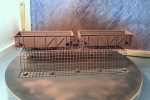
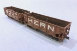
For weathering, I first dry brushed a little light rust and dark rust onto the car, mostly on the inside to simulate a few years of wear with the paint just starting to wear through where the coal repeatedly tugs at it. Next I gave all surfaces of the car a couple coats of black wash (water with a dab of paint). I worked one set of sides at a time (one “SOUT” and one “HERN”) to ensure the weathering was consistent across cars, brushing on the wash, letting it sit for a couple minutes, then dabbing and streaking it off down the sides with a moist paper towel. I followed the black wash with a single wash of tan. The final weathering was some black airbrushing inside the hopper and along the bottom followed by some light tan airbrushing on the sides and trucks.
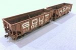
Finished 100T articulated hopper showing the huge “SOUT” and “HERN” lettering
I’m pretty happy with how this car turned out. It’s definitely unique and is bound to be a conversation piece on the layout. I can’t wait to watch the first operator trying to uncouple the dummy couplers so I can give them a little history lesson in Southern innovation!
Step 1. Print the artwork, cover with masking tape, and print again
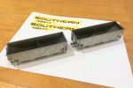
Step 2. Paint the sides of the cars white
Step 3. Cut out the letters using a sharp blade and straightedge
Step 4. Apply the lettering masks to the car, cutting around the ribs
Step 5. Paint the car (I primed with black first)
Step 6. Let the paint dry
Step 7. Carefully remove the masking using a sharp blade to get under the tape
Step 8. Ensure all tape is removed
Step 9. Paint the white lettering onto the ribs using a brush
Step 10. Dry brush some rust–I dry brushed lightly on the sides and a little heavier inside, then I did a black wash and a tan wash
Step 11. Finished car with some light black and tan airbrushing on the sides, trucks and interior
Finished car showing the brake detail on the ends
Finished 100T articulated hopper showing the huge “SOUT” and “HERN” lettering
The next installment in the “heritage fleet” of hoppers is an original Norfolk Southern 70T car still in gray paint. The NS wasn’t acquired until 1974, so this represents a car most likely in “yellow ball” captive service to the Appalachia, VA transloader in the late ’70s.
Orginal NS 70T hopper that’s seen a bit of service
The model is a factory painted Bowser hopper with some detail upgrades. Because it will be a light gray hopper in a sea of black and brown, I figured it would catch the eye more than most cars, so it has a higher level of detail than most of my cars. I removed the molded-on grabs and replaced them with wire, upgraded the brake detail, and added coupler cut bars and a trainline. Weathering if primarily drybrushing for the rust spots. I’m pretty happy with how the inside turned out–it’s two colors of rust drybrushing (dark rust for most with light rust around the paint edges) and a little black airbrushing.
These heritage cars are a lot of fun! I’ll need at least one 55T fishbelly hopper in NS gray as well.
Rusty inside of an original NS hopper made from a Bowser model
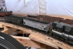
Two Southern “heritage fleet” hoppers being spotted
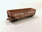
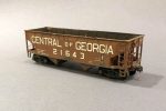
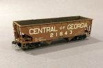
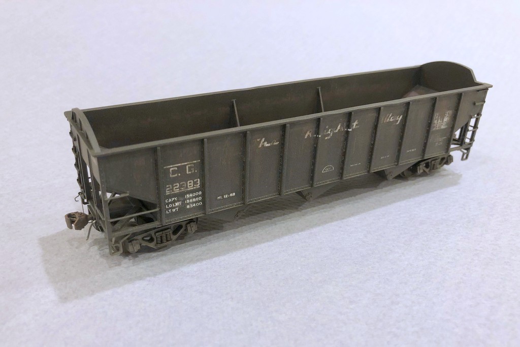
One of my goals is to have a fleet of “heritage fleet” hoppers representing each of the railroads purchased by the Southern and L&N in the 50s-70s. I’ve already got plenty of Interstate RR hoppers from the previous layout, but this is my first completed Central of Georgia hopper. Most of these were repainted into the Southern’s 74000 series, but some kept their CofGa reporting marks well beyond the merger. This model represents a car showing a lot of rust and wear and ready for the shop.
Old CG hopper ready for another trip to the shop for a repaint
It’s a stock, factory pained Atlas Trainman hopper with some detail upgrades including shaved-down grabs and a few wire details like the homemade trainline hoses and coupler cut bars. I spent most of the time on weathering. It’s mostly drybrushing to get the rust effects including the subtle ring inside the car. The data is supposed to represent a shop patch job, but it didn’t turn out as distinct as I would have liked. Lesson learned for next time.
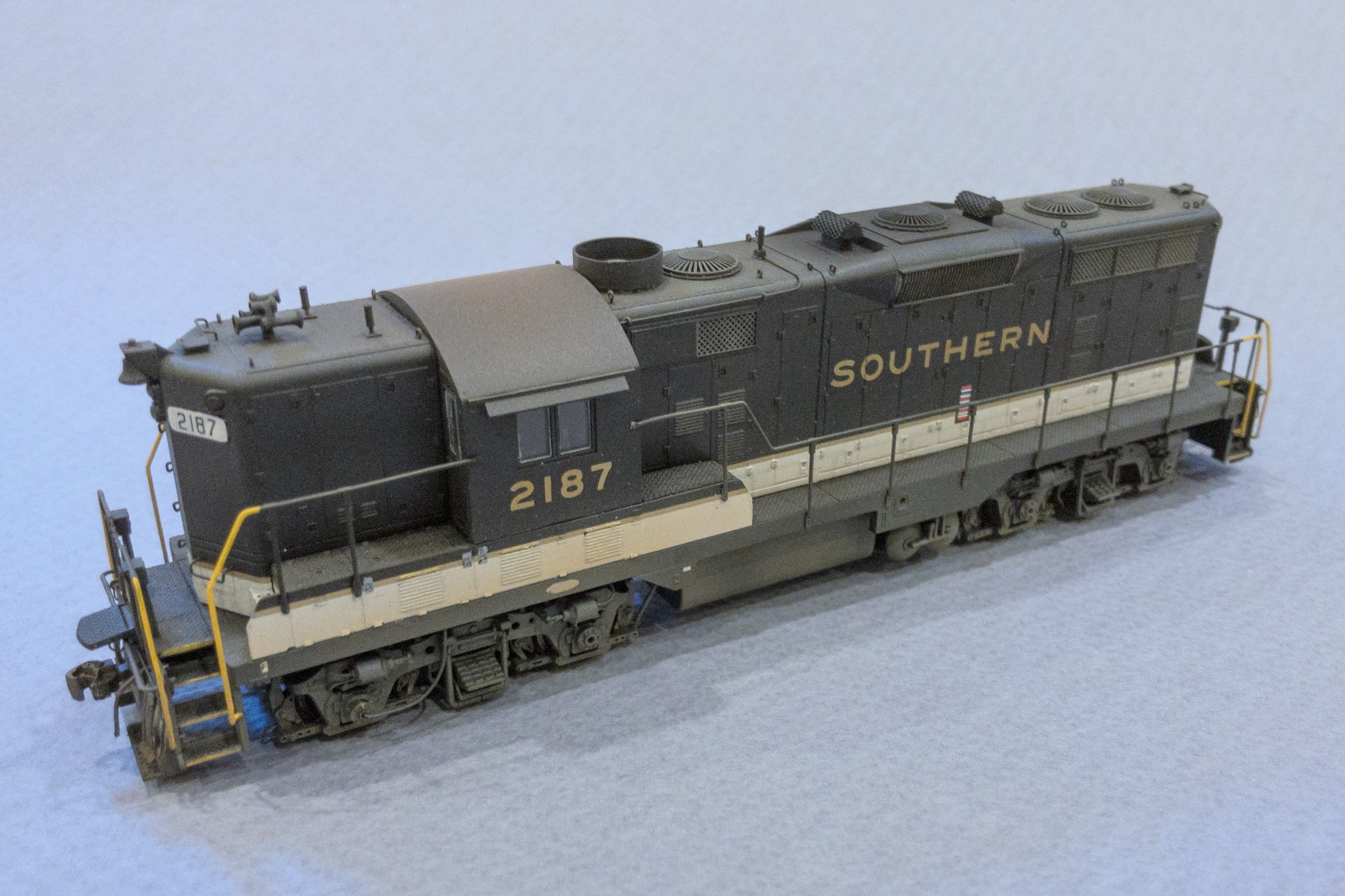
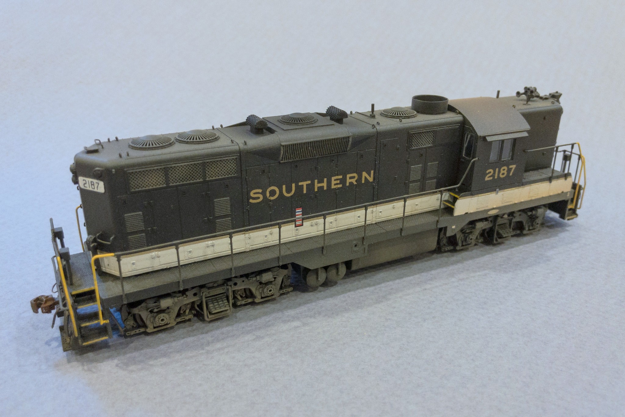
Today was a big day!… but it shouldn’t have been. It’s been an embarrassingly long time since I completed a locomotive model… like 7 years. Now it’s been less than a day as I put the finishing touches on Southern GP7 2187 today. This model started as a Proto 2000 GP7, and I’d gotten it through at least its initial detailing and coat of black paint several years ago. Last week, I finally decided it was time, and I decaled, added the last of the details, and weathered it.
Southern GP7 2187 from a modified Proto 2000 model
I modeled 2187 as she appeared around 1970. This was one of a handful of GP7s the Southern modified with Locotrol in the 1960s (hence the white number boards), but it seemed to spend most of its life in secondary service. Photos place it in southwestern Virginia in the late ’60s and again in ’71 after a trip to the shop that added the Southern-style sunshades and ACI tag. Modifications to the model include a 36″ dynamic fan, fan shroud and blank grill cover, scratchbuilt spark arrestors, modified fuel tank skirting, Southern-style sunshades, 5-chime horn, and Locotrol details like the 3 antennas and extra conduit.
Southern GP7 2187 from a modified Proto 2000 model
Southern GP7 2187 from a modified Proto 2000 model
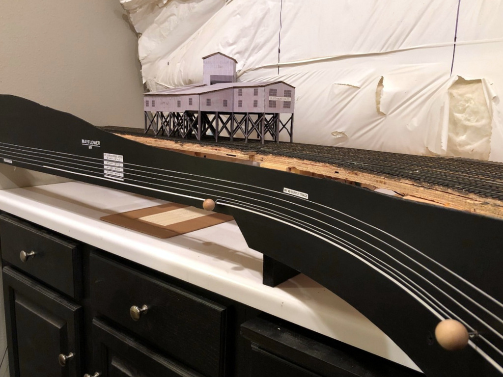
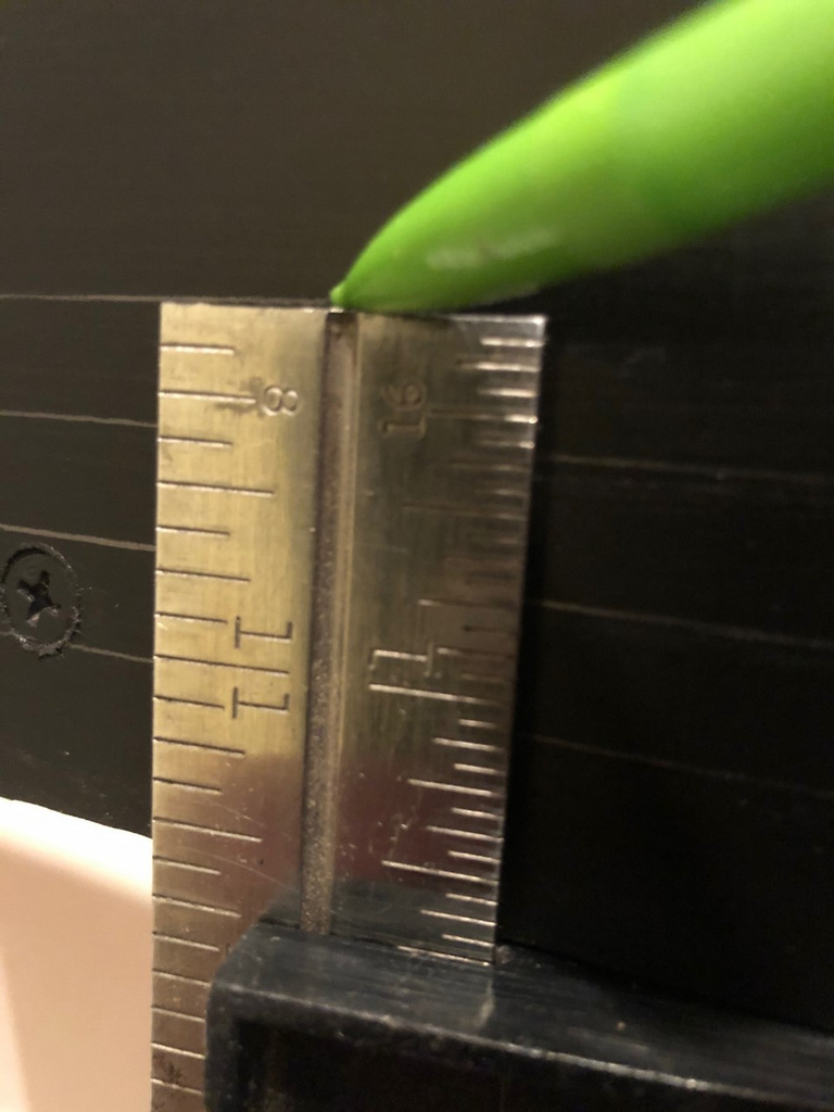
Finished fascia and labels at MayflowerI set a combination square to the right height and slide it along the bottom of the fascia while dragging a pencil across the top to draw straight lines for the track diagram
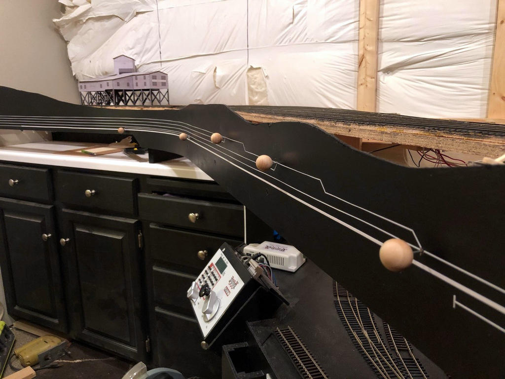
Working on the fascia is very mundane and unexciting, but as a human factors engineer by education, I take my fascia very seriously! On most layouts, the fascia is the primary interface between operators and the layout. It’s often where we place controls and place names, and it’s also a blank canvas we can use to help our operators better understand the scene they’re interacting with. Like many who perform switching operations on their layouts, I like to use the fascia to help operators understand as much as possible about towns, tracks and industries to aid in making their switching moves.
As far as construction goes, my fascia is just sheet Masonite fastened to the benchwork with drywall screws. I cut it in thick strips that will account for all the vertical scenery contours along the front edge. Where there are noticeable gaps or indentations from the screws, I touch things up with lightweight spackling compound and wipe it smooth with a damp cloth after letting it harden for about an hour–this saves a lot of time sanding later. Then I draw in the ground contour with a pencil and cut it with a jigsaw. A little black paint, and things are ready for the operator features.
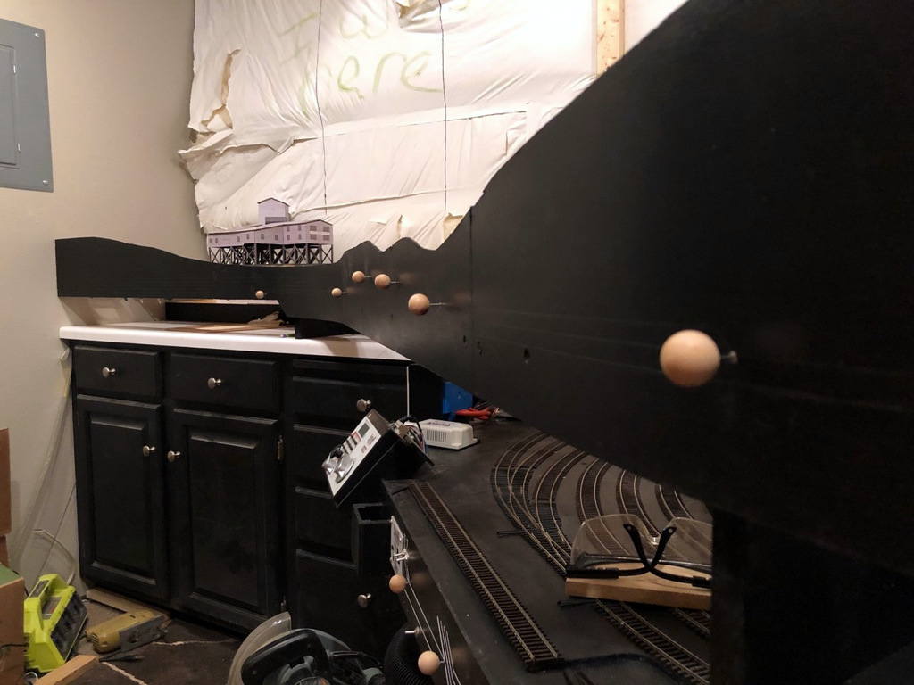
All the Mayflower switch controls installed–they’re at different elevations to line up with the track diagram that will be installed on the fascia
On my last layout, I drew the track diagram onto the front of the fascia, and it worked so well I decided to continue it on my new layout. It’s essentially an elongated track diagram like you’d find in a railroad track chart that lines up with the adjacent track and switches on the layout. I draw the lines parallel to the bottom of the fascia 3/8″ apart. To draw them, I’ll set a combination square so the end of the ruler is at the exact height I want when the square is pressed against the bottom of the fascia, then I’ll run the combination square around the bottom of the fascia while dragging a pencil along the top to draw it onto the fascia. I draw the switches onto the fascia at 45 degree angles with the convergence drawn where I want the switch control rod to be placed (directly perpendicular to the switch mechanism usually). One lesson learned from my last layout I was able to incorporate into this one is that the “straight” line through a switch control is the “normal” position of the switch while the “divergent” line represents the “thrown” position. It required a little “wiggling” of the track lines in the yard ladder to make this work, but it’s intended to help operators understand how to set the switches before departing a town.
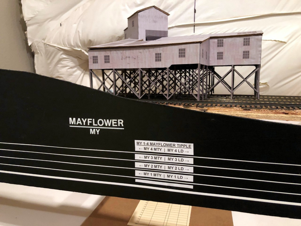
Finished fascia labels with the town name and siding identifiers for the Mayflower Tipple
I installed the switch control rods (see full article on switch control mechanisms here) after the lines were drawn but before placing the graphic tape on the fascia to represent the tracks. I use two sizes of white graphic tape for the tracks, 3/32″ to represent the main, and 1/32″ to represent sidings. This offers another visual clue for operators so they know which tracks not to block and what to leave clear after leaving town. Next come the labels. Every town on the layout has both a name and a unique 2-letter destination code for routing cars. In this case, Mayflower is represented by “MY.” Within each town, each track has a unique number, for example, MY 1 is the tipple track for the Mayflower Tipple closest to the main. For tipples, I also designate where the empty (MTY) and loaded (LD) cars go, so an empty hopper destined to be loaded on Mayflower’s outermost track would need to be placed at MY 4 MTY. Towns are labeled with large dry transfer lettering with the town name above a line and its destination code in smaller letters below. I also cut a small gap in each track tape on the fascia near the switch and use dry transfer numbers to label each track by number. Industries are given white labels with black lettering that gives the industry name, town initials, track number(s) and MTY | LD track dividing line if needed (see picture of the Mayflower Tipple and its labels). If two or more industries are on the same track, I use a “B,” “C” or so forth to denote each spotting location. In the case of Mayflower, I’ve identified a spot on load track 4 where I might have operators occasionally spot cars of supplies and a spot on the tail track of the main where I might have them spot covered hoppers of AN–each of these spots has its own industry label adjacent to the correct track on the fascia track diagram to make it clear where to spot the cars.
There’s nothing really novel here, but I do think this method of using track diagrams on the fascia and integrating switch controls, town names and industry track designators with unique operational codes goes a long way toward making the layout more intuitive and operator-friendly.
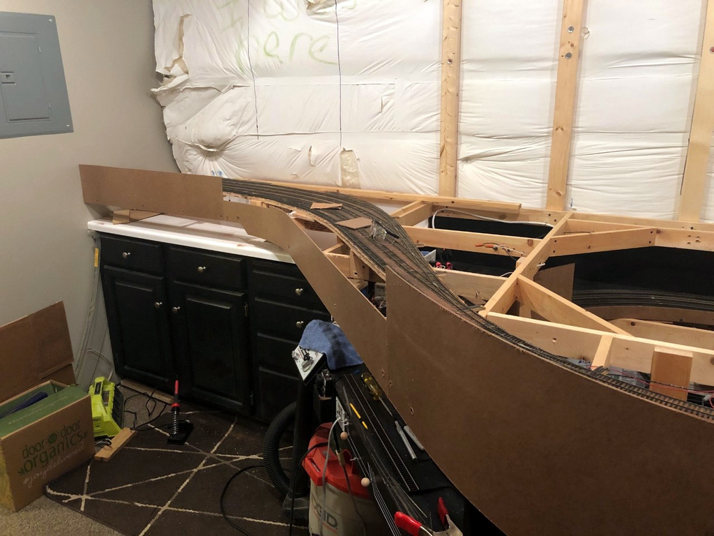
Roughed in masonite fascia awaiting sculpting
Here the fascia has been cut to shape, sanded, and painted
I set a combination square to the right height and slide it along the bottom of the fascia while dragging a pencil across the top to draw straight lines for the track diagram
All the Mayflower switch controls installed–they’re at different elevations to line up with the track diagram that will be installed on the fascia
Extra wood glued behind the fascia supports the switch throw rods and makes the fascia stronger
Nearly final fascia in Mayflower with the track diagram in place
Finished fascia and labels at Mayflower
Finished fascia labels with the town name and siding identifiers for the Mayflower Tipple
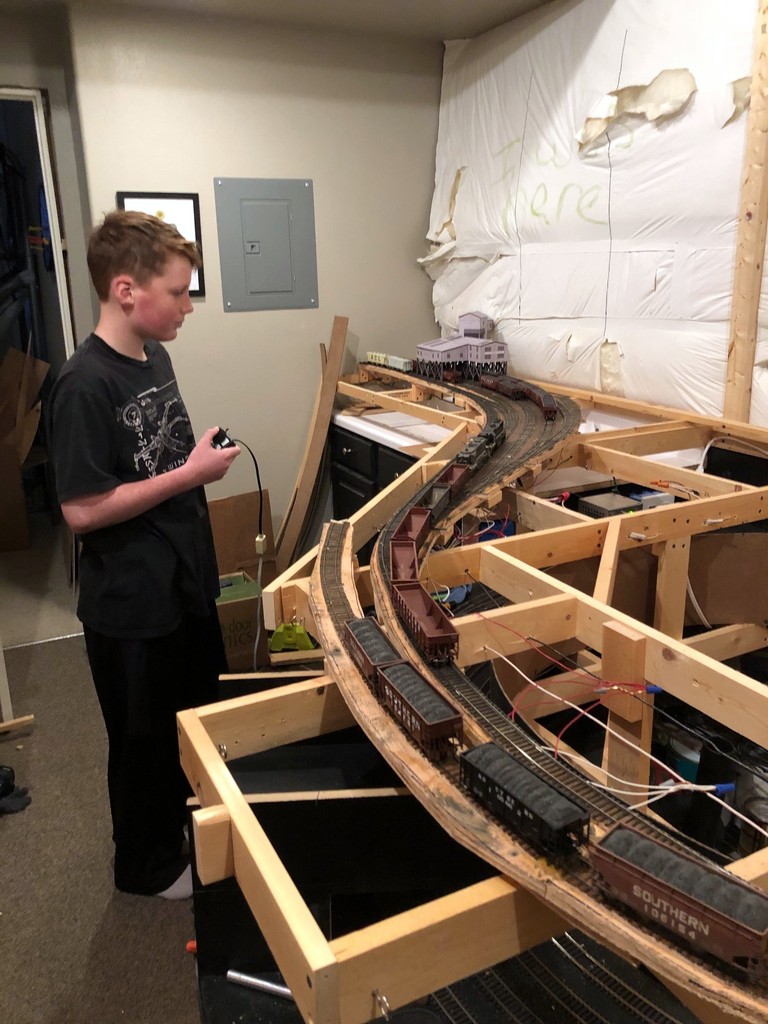
My son, Drew, was the engineer for the first mine run on the layout, a “Black Mountain Local” working Mayflower and Baker
Saturday was a big day–the first operational train worked the first loaders on the layout. It was a “Black Mountain Local” with me as conductor and my son, Drew, as engineer. Things overall went pretty smoothly with only a single derailment in the entire session (not bad for the first time operating on hand-laid track). Our power was GP38 2877 and GP30 2534. We picked up our train of 13 empty hoppers and a single loaded ACL covered hopper (AN for the mines). Awaiting us in Baker were 4 “yellow ball” loads for the transloader in Appalachia followed by 8 loads at Mayflower and an empty covered hopper.
The tracks at both Baker and Mayflower are stub tracks (prototypical), so most of our time was spent pulling loads to clear tracks and running around empties 5-at-a-time in the single run-around track. It was a great time to teach my son about run-arounds, delayed couplers, and how to think through switching moves. Despite the lack of scenery or even operational throws for the switches (I had to reach under and throw the mechanisms directly), it was 30 minutes of pure joy more than 3 years in the making (since we moved in). We finished the shift with the entry of this “milestone” marker on the benchwork to commemorate the event.
“Milestone” entry for the first mine run worked on the layout
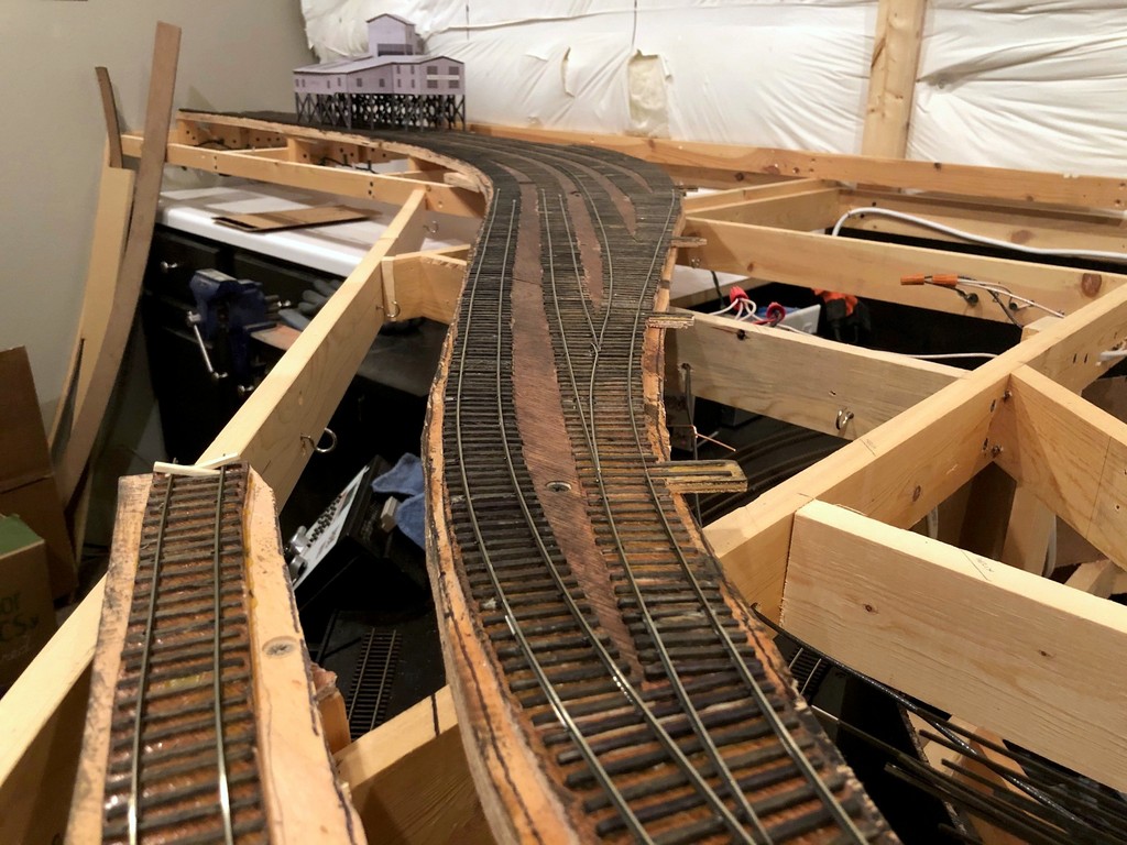
View of the finished load tracks from the top of the tipple–note the track that’s been removed on the left side (thought it would make a cool detail)
I’ve completed laying rails on the Mayflower section of the railroad, and I’m just about ready to run the first mine run–exciting times! Everything is hand-laid, and I’ll share a little about my technique. I lay everything in place instead of using a jig because I find the track flows better. I use code 83 for the main and code 70 for sidings, and I spike everything with small spikes, about every 5th tie except for switches. I like to work outside-in as you’ll see in the pictures of the load yard ladder. This means the first few switches take a while because you’re notching for the points of ALL the switches on that piece of rail, but it speeds up as you go because you’ve already filed pieces up-front. I don’t pay much attention to frog numbers or curves–I just lay them as the ties dictate (and remember, the ties were laid down based on outlines traced around flex track, so that’s where I check radii and things).
You also might notice that I’m not putting in guard rails alongside the frogs for some switches which is prototypical for sidings in some areas of the country. I use them on both sides of every mainline switch, and I use them on the tightest curve side of every curved switch. For the rest, I test cars and put them in as needed. If your frog is straight, you probably wont need them. If your frog is curved at all, you probably will. I like the look of the switches with no guard rails because it emphasizes “siding.” I also use the track to tell part of the story, so you’ll notice that I laid an extra switch’s worth of ties for a 5th track under the tipple that has been removed (try doing THAT with commercial track)–Mayflower had a spot to load on a 5th track, but track diagrams in my era only show 4 tracks. I’ve modeled it as if they just pulled up the rails and laid through the switch instead of pulling up all the ties.
All the feeders (a gazillion) got dropped and attached yesterday, so I just need to set out some cars and recruit my engineer for the first-ever mine run on the layout. Woohoo!
This is the siding for a small truck dump at Baker–I used cookie cutter benchwork to get some good elevation difference, and I laid the rails for the siding very sloppily from side-to-side to show kinks of a well-used and minimally maintained siding
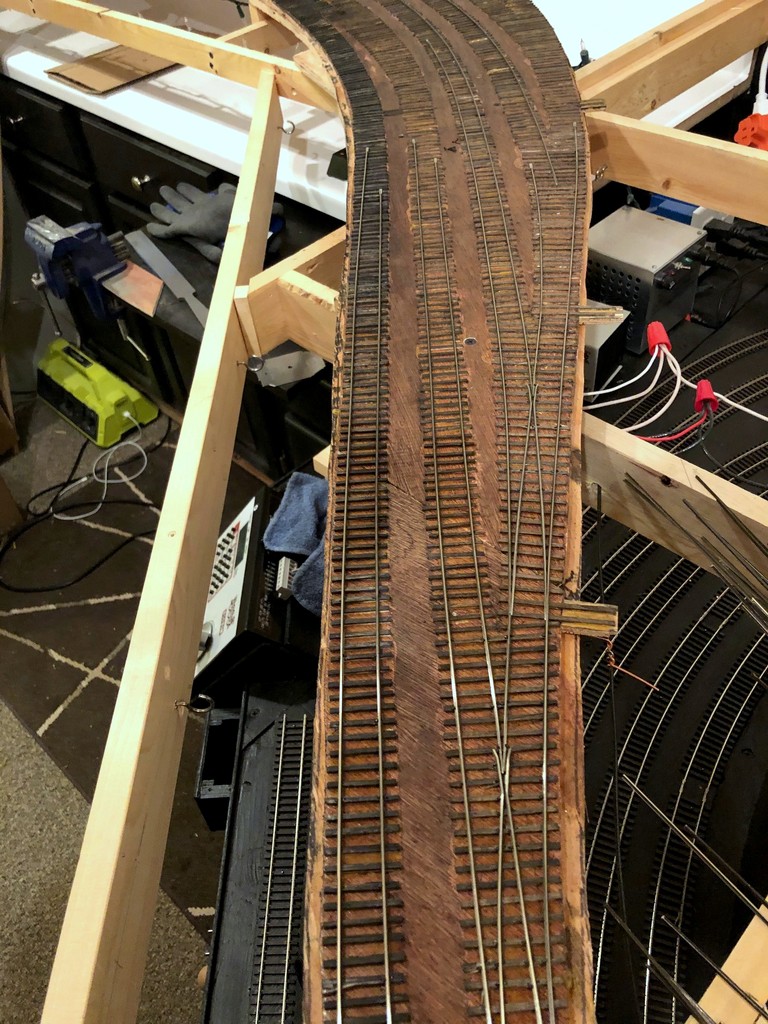
Overview of the ladder in Mayflower with the first couple rails in–I work “outside-in”
A little further along showing some of the “inside” rails being laid
Nearly finished yard ladder. The point rails haven’t been bent yet to put inward tension on the throw bar (which will be inserted soon)
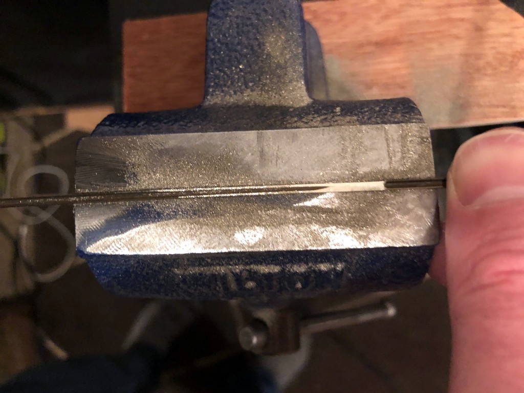
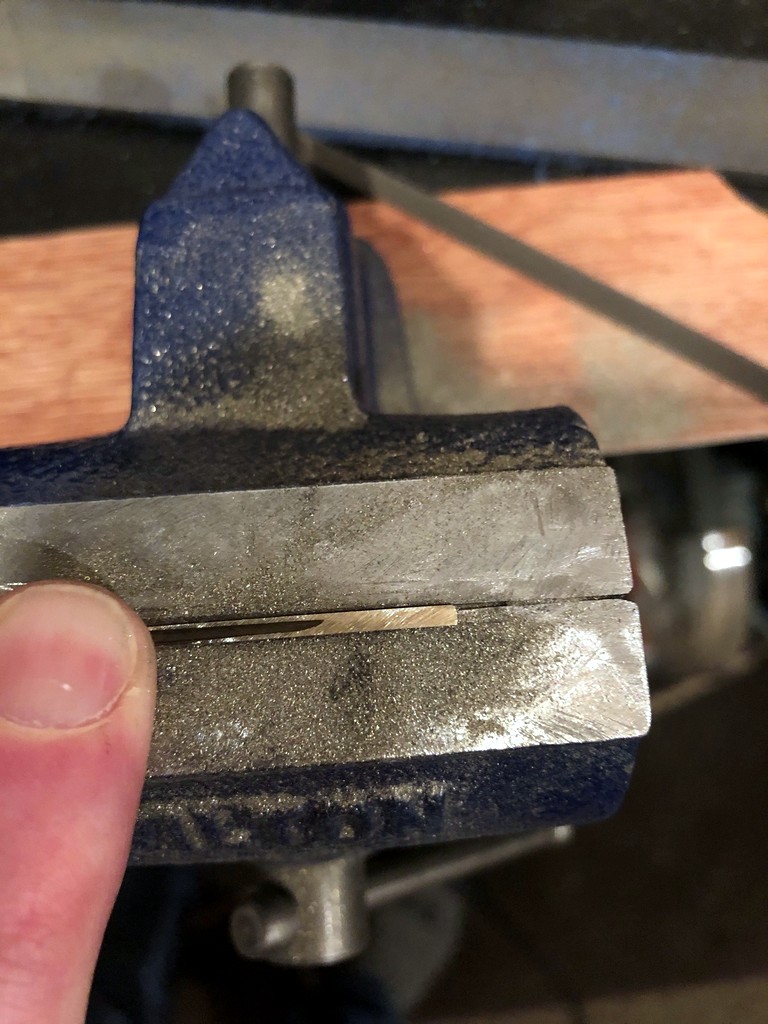
Filing one of the notches in the stock rail–I just use a triangle file and bench vise with the rail sitting in the seam
I file points with a triangle file on top of a small bench vise–the seam holds the rail in place well enough without clamping
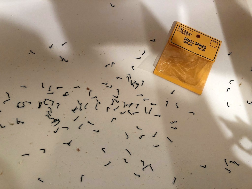
I’m not too impressed with the “new and improved” Micro Engineering small spikes–they bend a WHOLE lot easier than the original
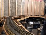
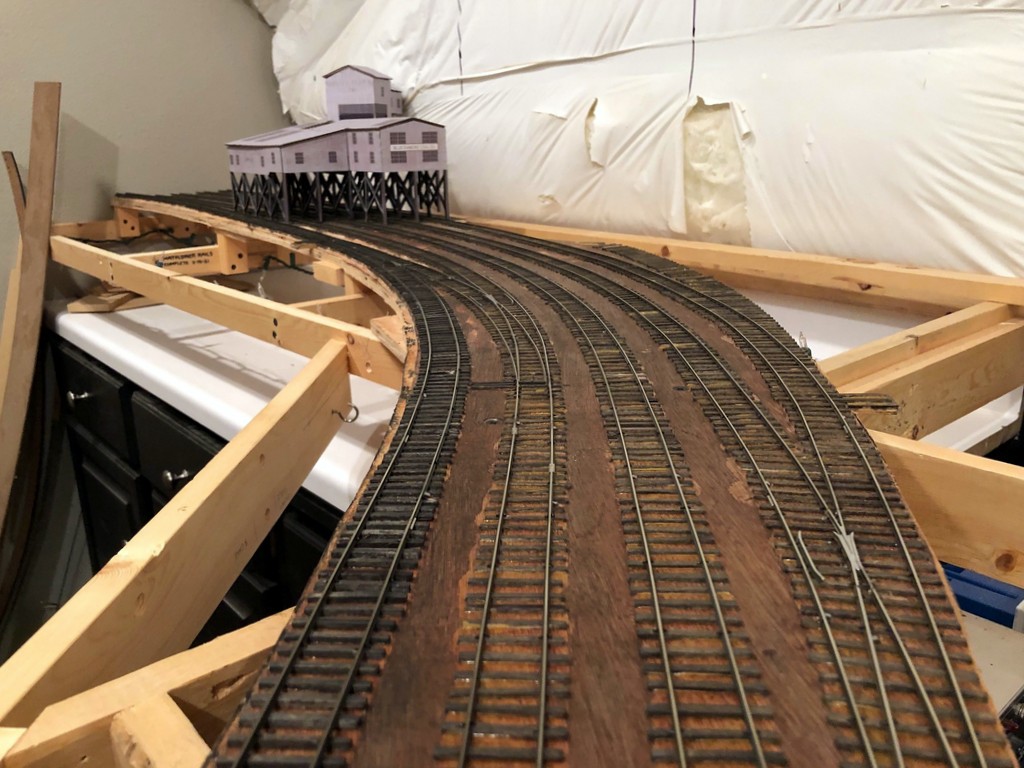
Looking “north” at the finished tracks of the load yard at Mayflower with the tipple mock-up in the background
View of the finished load tracks from the top of the tipple–note the track that’s been removed on the left side (thought it would make a cool detail)
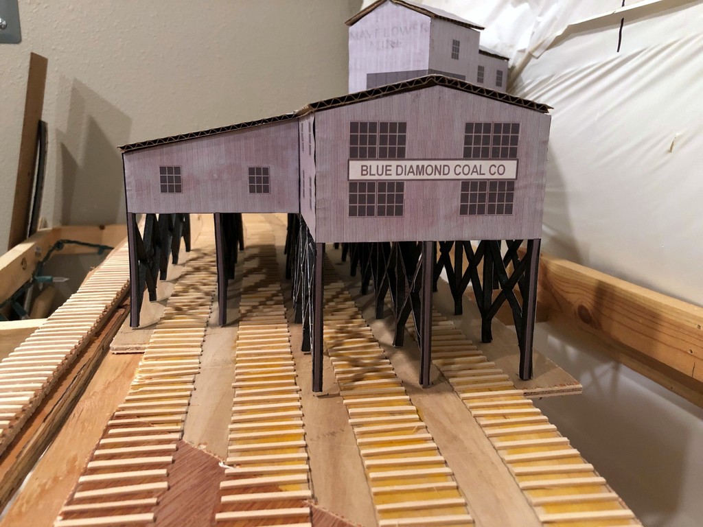
A close-up of the Mayflower Tipple mock-up with ties running underneath
Made some progress this week on the Mayflower Branch section of the layout. All the ties have been laid! This is a tedious but simple process made a lot easier by the outline of track left over from tracing flextrack onto my subroadbed for cutting. I just place the material (1/4″ door skin for me) on top of the layout, place thumbtacks in the holes of a piece of limber Atlas flex track, fasten the track down with the pins using turn radius templates and “eyeballing” the rest, then use a pencil to trace down both sides of the track. For marking switches, I leave a portion of the track fastened and move the loose section to trace the divergent track. After tracing, where the pencil marks diverge is the location for the turnout points and longer block ties. After the subroadbed is secured in place with risers, screws and glue, I’ve got a perfect template for the tracks on the layout for laying ties (more about making and laying ties below).
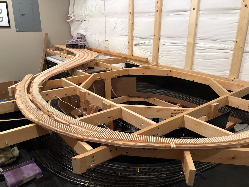
Overview of the Mayflower Branch section of the layout with the ties freshly installed (this one’s for you, Bill)
Now that all the ties are in place and I have the mock-up of the Mayflower Tipple, I can really start to visualize the entire scene. I’m really liking how the track snakes into the scene, and I think the gentle curve into the tipple will really look cool with strings of hoppers hanging out. You’ll also notice the tracks run into the wall–I didn’t have enough room to model the empty yard, just some space for empties above the tipple. This was an easy compromise to make for space because the empty yard at Mayflower was a stub-ended affair, so crews still had to run around and shove cuts of empty hoppers, just as they’ll need to do here. I can’t wait to get the rails down and operate that first mine run! There’s a lot of rail-laying between now and then, but it’s good to see it coming together.
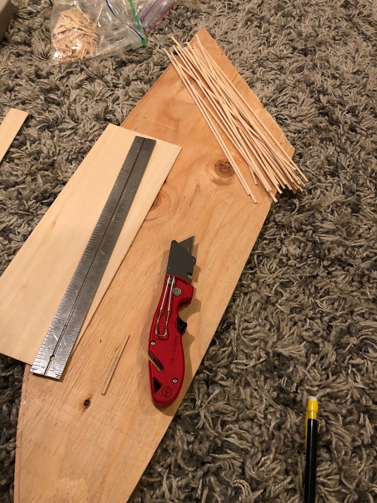
My “workbench” for making ties–I cut strips from 1/16 and 3/32″ basswood to use for siding and mainline ties, respectively.
Making Ties. Rather than buy bags of ties, I cut my own from sheets of basswood, 1/16″ for siding ties and 3/32″ for mainline ties. It’s not that ties on the prototype were different heights, but using different height ties on the layout keeps siding tracks a little lower than the main (very prototypical). I use a “spacer tie” to line up a metal straightedge the proper distance from the edge of the basswood board, then cut it with a couple strokes of a sharp utility blade. Most sheets come in 2′ length, and I’ve found it easier to cut it to 1′ length first so I don’t have to move the straightedge in the middle of a cut. With a bunch of sticks in hand, I then use a Northwest Shore Line “Chopper II” (amazing tool) and a scale rule to cut the ties in .5′ increments from a scale 8.5′ to 16.5′ with a separate, well-marked ziploc baggie for each size and length. Standard ties are 8.5′, and switches require a few of each longer size as you progress up the switch with 16′ ties for block ties at the points.
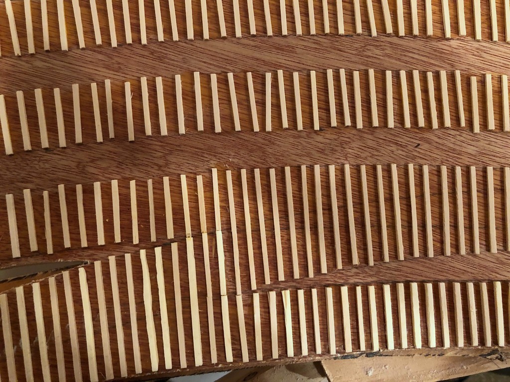
Ties tell a story about the type of track you’re modeling from mainline to well-used siding
Laying Ties. Laying ties is a simple matter of putting down some wood glue on the subroadbed and placing them. I work in sections of about 8-12″ at a time to make sure the glue doesn’t dry before the tie gets there. Ties tell a story about the kind of track you’re modeling, and it’s one of the reasons I love hand-laying track. Mainline track should be in good working order with closely spaced ties perpendicular to the rails and just a little side-to-side variation. Well kept sidings are similar but with perhaps a bit wider spacing between ties. For old, well-used sidings like you’d see at coal tipples, I’m pretty haphazard with my ties, allowing some of them to kink off perpendicular and lots of variation in spacing and alignment from side-to-side. It looks absolutely disgusting before the rails go on, but the effect is more subtle once the ties are stained and the rails are in place. I love disgusting looking track that still runs well, so I can be pretty aggressively messy when laying siding ties!