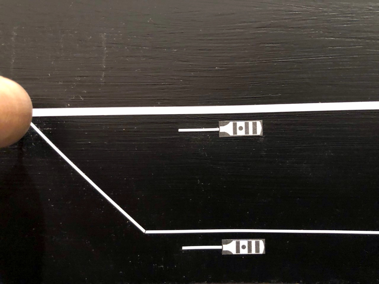
A couple of Southern-style whistle posts on the fascia track chart
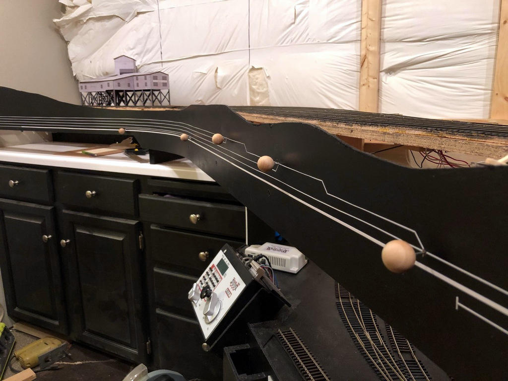
I thought I’d share a little addition to the fascia–Southern whistle posts. I never thought about this on my last layout because none of my locomotives were sound equipped. Now that I’m moving toward sound, I wanted a way to tell crews when they need to sound the horn for grade crossings. On the prototype, posts are set up on either side of a grade crossing to give the crew enough time to sound off their loooong, loooong, short, looooooooong blast of the whistle or horn. While most railroads used a white sign with a prominent “W” for this purpose, the Southern used a vertically elongated white sign with a stripe, a stripe, a dot, and a stripe (for long, long, short, long). I decided I wanted my posts to be Southern-esque, so I created a simple black-and-white version from basic shapes in MS PowerPoint, sized them to about 1/2″ high, and printed them on a label sheet.
I cut them out and placed them about 15-18″ from the sites of future grade crossings (I have no roads modeled yet) which gives crews about 4-5 seconds of warning at 10 scale MPH, probably about right for the areas where these grade crossings reside. After placing the whistle post stickers on the right side of the track diagram (making them horizontal), I added a little 1/2″ piece of 1/32″ white graphics tape representing the post for the sign to ensure operators can tell which direction the sign is pointing. Once I have scenery, I’ll add some real scale whistle posts trackside, but for now, these will give crews one more prototypical thing to remember while operating their trains.
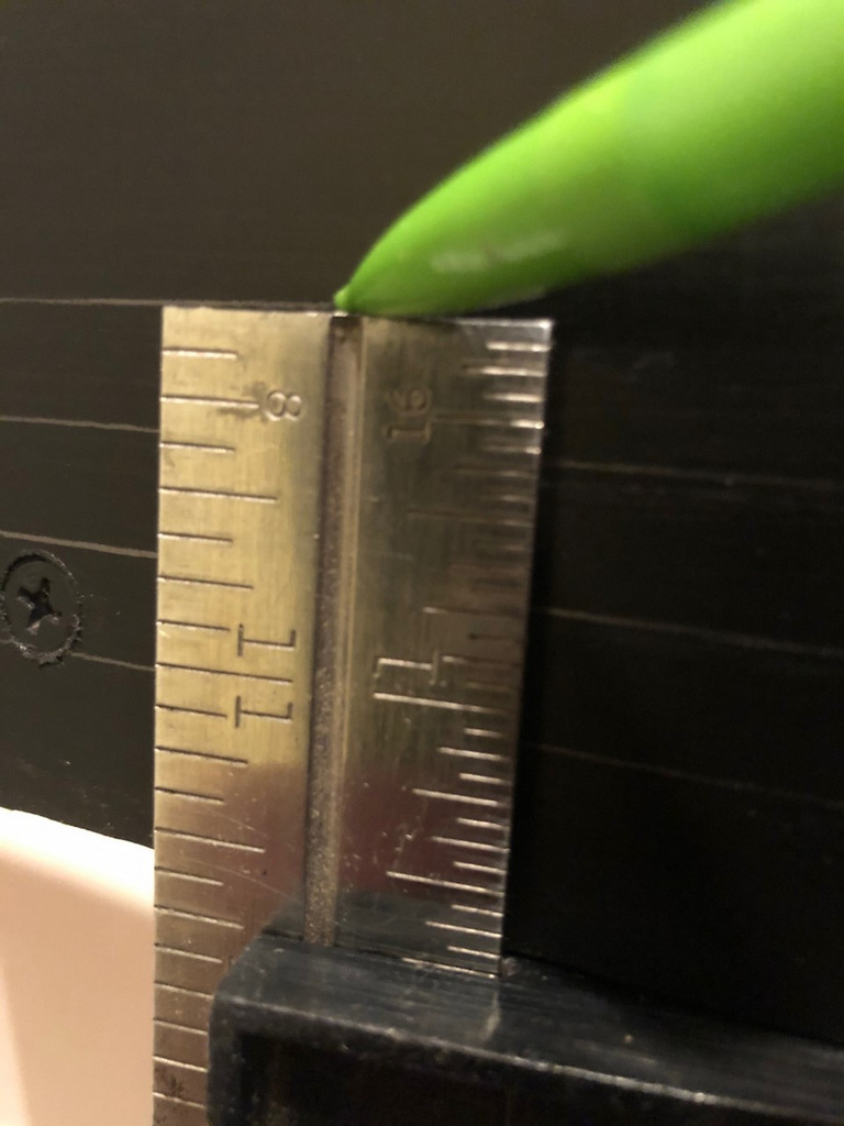
Finished fascia and labels at MayflowerI set a combination square to the right height and slide it along the bottom of the fascia while dragging a pencil across the top to draw straight lines for the track diagram
Working on the fascia is very mundane and unexciting, but as a human factors engineer by education, I take my fascia very seriously! On most layouts, the fascia is the primary interface between operators and the layout. It’s often where we place controls and place names, and it’s also a blank canvas we can use to help our operators better understand the scene they’re interacting with. Like many who perform switching operations on their layouts, I like to use the fascia to help operators understand as much as possible about towns, tracks and industries to aid in making their switching moves.
As far as construction goes, my fascia is just sheet Masonite fastened to the benchwork with drywall screws. I cut it in thick strips that will account for all the vertical scenery contours along the front edge. Where there are noticeable gaps or indentations from the screws, I touch things up with lightweight spackling compound and wipe it smooth with a damp cloth after letting it harden for about an hour–this saves a lot of time sanding later. Then I draw in the ground contour with a pencil and cut it with a jigsaw. A little black paint, and things are ready for the operator features.
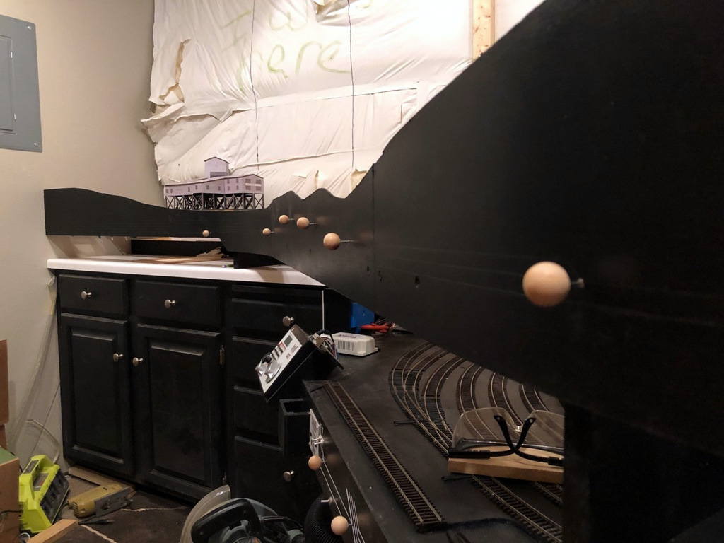
All the Mayflower switch controls installed–they’re at different elevations to line up with the track diagram that will be installed on the fascia
On my last layout, I drew the track diagram onto the front of the fascia, and it worked so well I decided to continue it on my new layout. It’s essentially an elongated track diagram like you’d find in a railroad track chart that lines up with the adjacent track and switches on the layout. I draw the lines parallel to the bottom of the fascia 3/8″ apart. To draw them, I’ll set a combination square so the end of the ruler is at the exact height I want when the square is pressed against the bottom of the fascia, then I’ll run the combination square around the bottom of the fascia while dragging a pencil along the top to draw it onto the fascia. I draw the switches onto the fascia at 45 degree angles with the convergence drawn where I want the switch control rod to be placed (directly perpendicular to the switch mechanism usually). One lesson learned from my last layout I was able to incorporate into this one is that the “straight” line through a switch control is the “normal” position of the switch while the “divergent” line represents the “thrown” position. It required a little “wiggling” of the track lines in the yard ladder to make this work, but it’s intended to help operators understand how to set the switches before departing a town.
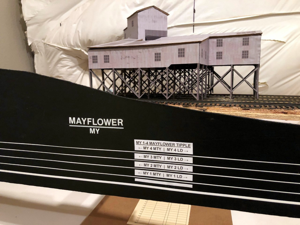
Finished fascia labels with the town name and siding identifiers for the Mayflower Tipple
I installed the switch control rods (see full article on switch control mechanisms here) after the lines were drawn but before placing the graphic tape on the fascia to represent the tracks. I use two sizes of white graphic tape for the tracks, 3/32″ to represent the main, and 1/32″ to represent sidings. This offers another visual clue for operators so they know which tracks not to block and what to leave clear after leaving town. Next come the labels. Every town on the layout has both a name and a unique 2-letter destination code for routing cars. In this case, Mayflower is represented by “MY.” Within each town, each track has a unique number, for example, MY 1 is the tipple track for the Mayflower Tipple closest to the main. For tipples, I also designate where the empty (MTY) and loaded (LD) cars go, so an empty hopper destined to be loaded on Mayflower’s outermost track would need to be placed at MY 4 MTY. Towns are labeled with large dry transfer lettering with the town name above a line and its destination code in smaller letters below. I also cut a small gap in each track tape on the fascia near the switch and use dry transfer numbers to label each track by number. Industries are given white labels with black lettering that gives the industry name, town initials, track number(s) and MTY | LD track dividing line if needed (see picture of the Mayflower Tipple and its labels). If two or more industries are on the same track, I use a “B,” “C” or so forth to denote each spotting location. In the case of Mayflower, I’ve identified a spot on load track 4 where I might have operators occasionally spot cars of supplies and a spot on the tail track of the main where I might have them spot covered hoppers of AN–each of these spots has its own industry label adjacent to the correct track on the fascia track diagram to make it clear where to spot the cars.
There’s nothing really novel here, but I do think this method of using track diagrams on the fascia and integrating switch controls, town names and industry track designators with unique operational codes goes a long way toward making the layout more intuitive and operator-friendly.
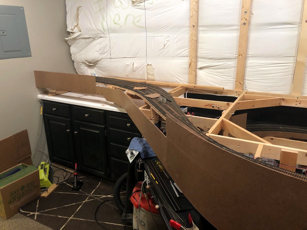
Roughed in masonite fascia awaiting sculpting
Here the fascia has been cut to shape, sanded, and painted
I set a combination square to the right height and slide it along the bottom of the fascia while dragging a pencil across the top to draw straight lines for the track diagram
All the Mayflower switch controls installed–they’re at different elevations to line up with the track diagram that will be installed on the fascia
Extra wood glued behind the fascia supports the switch throw rods and makes the fascia stronger
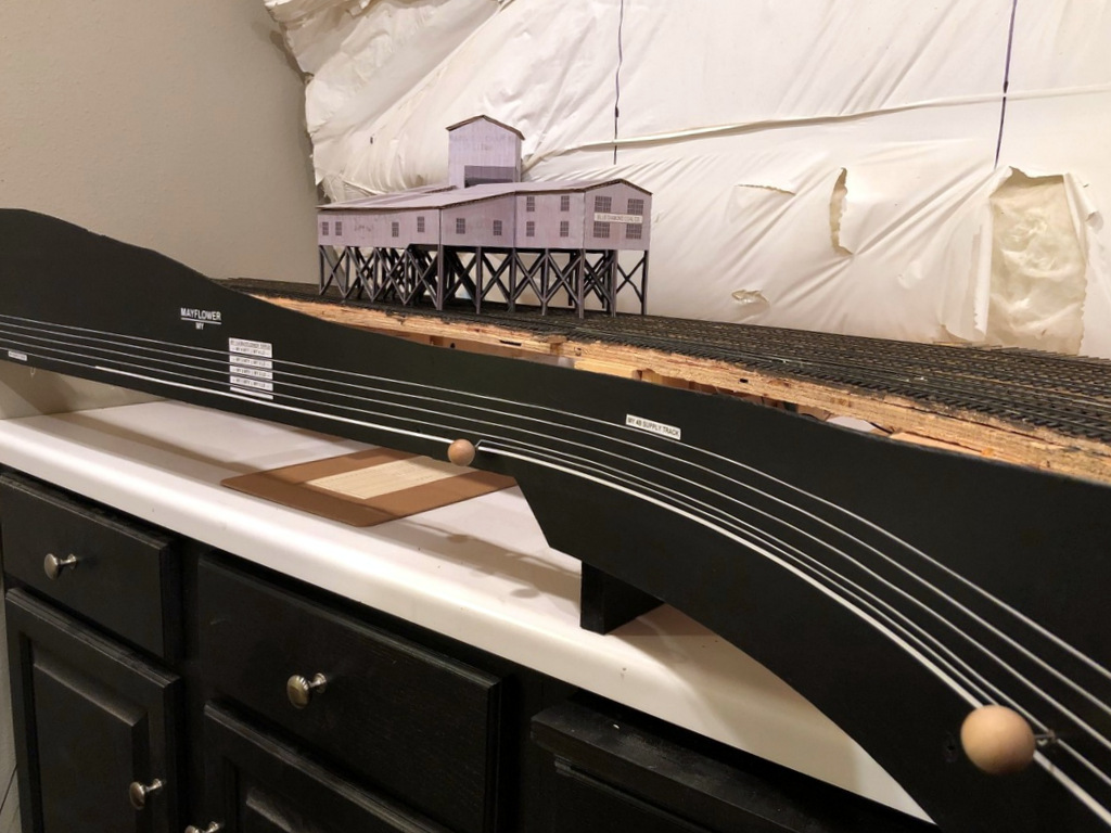
Nearly final fascia in Mayflower with the track diagram in place
Finished fascia and labels at Mayflower
Finished fascia labels with the town name and siding identifiers for the Mayflower Tipple
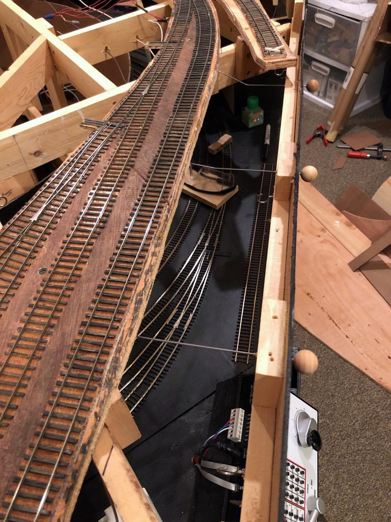
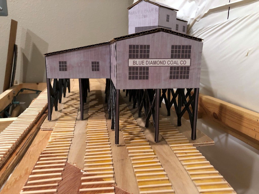
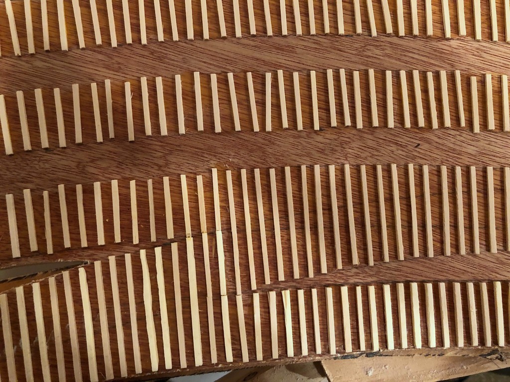
A close-up of the Mayflower Tipple mock-up with ties running underneath
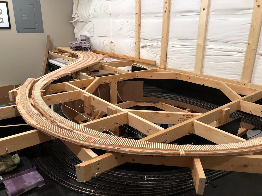
Made some progress this week on the Mayflower Branch section of the layout. All the ties have been laid! This is a tedious but simple process made a lot easier by the outline of track left over from tracing flextrack onto my subroadbed for cutting. I just place the material (1/4″ door skin for me) on top of the layout, place thumbtacks in the holes of a piece of limber Atlas flex track, fasten the track down with the pins using turn radius templates and “eyeballing” the rest, then use a pencil to trace down both sides of the track. For marking switches, I leave a portion of the track fastened and move the loose section to trace the divergent track. After tracing, where the pencil marks diverge is the location for the turnout points and longer block ties. After the subroadbed is secured in place with risers, screws and glue, I’ve got a perfect template for the tracks on the layout for laying ties (more about making and laying ties below).
Overview of the Mayflower Branch section of the layout with the ties freshly installed (this one’s for you, Bill)
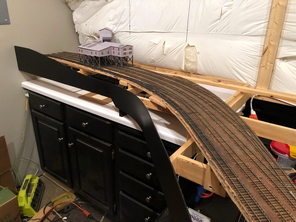
Now that all the ties are in place and I have the mock-up of the Mayflower Tipple, I can really start to visualize the entire scene. I’m really liking how the track snakes into the scene, and I think the gentle curve into the tipple will really look cool with strings of hoppers hanging out. You’ll also notice the tracks run into the wall–I didn’t have enough room to model the empty yard, just some space for empties above the tipple. This was an easy compromise to make for space because the empty yard at Mayflower was a stub-ended affair, so crews still had to run around and shove cuts of empty hoppers, just as they’ll need to do here. I can’t wait to get the rails down and operate that first mine run! There’s a lot of rail-laying between now and then, but it’s good to see it coming together.
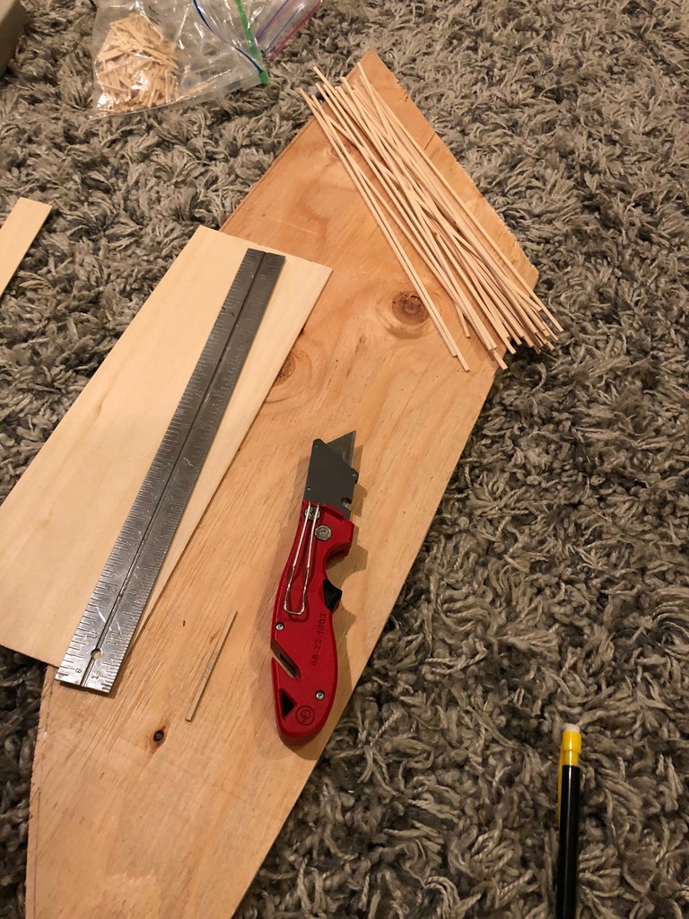
My “workbench” for making ties–I cut strips from 1/16 and 3/32″ basswood to use for siding and mainline ties, respectively.
Making Ties. Rather than buy bags of ties, I cut my own from sheets of basswood, 1/16″ for siding ties and 3/32″ for mainline ties. It’s not that ties on the prototype were different heights, but using different height ties on the layout keeps siding tracks a little lower than the main (very prototypical). I use a “spacer tie” to line up a metal straightedge the proper distance from the edge of the basswood board, then cut it with a couple strokes of a sharp utility blade. Most sheets come in 2′ length, and I’ve found it easier to cut it to 1′ length first so I don’t have to move the straightedge in the middle of a cut. With a bunch of sticks in hand, I then use a Northwest Shore Line “Chopper II” (amazing tool) and a scale rule to cut the ties in .5′ increments from a scale 8.5′ to 16.5′ with a separate, well-marked ziploc baggie for each size and length. Standard ties are 8.5′, and switches require a few of each longer size as you progress up the switch with 16′ ties for block ties at the points.
Ties tell a story about the type of track you’re modeling from mainline to well-used siding
Laying Ties. Laying ties is a simple matter of putting down some wood glue on the subroadbed and placing them. I work in sections of about 8-12″ at a time to make sure the glue doesn’t dry before the tie gets there. Ties tell a story about the kind of track you’re modeling, and it’s one of the reasons I love hand-laying track. Mainline track should be in good working order with closely spaced ties perpendicular to the rails and just a little side-to-side variation. Well kept sidings are similar but with perhaps a bit wider spacing between ties. For old, well-used sidings like you’d see at coal tipples, I’m pretty haphazard with my ties, allowing some of them to kink off perpendicular and lots of variation in spacing and alignment from side-to-side. It looks absolutely disgusting before the rails go on, but the effect is more subtle once the ties are stained and the rails are in place. I love disgusting looking track that still runs well, so I can be pretty aggressively messy when laying siding ties!
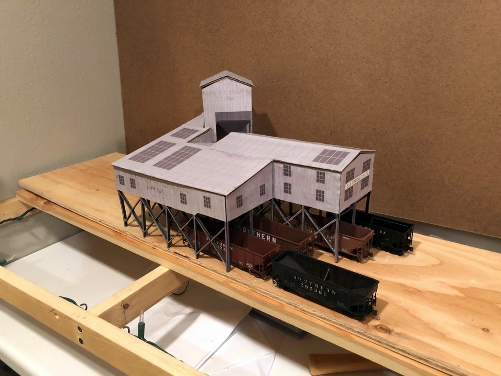
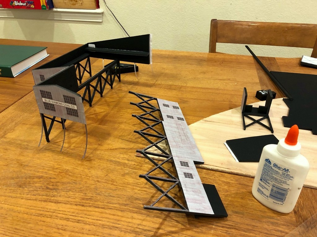
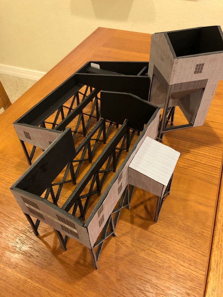
The final tipple mock-up in place on the layout showing its size relative to the benchwork and hoppers
I’ve finally started laying subroadbed onto the main level of the layout, and I’ve chosen the section between Baker and Mayflower as my first scene (see track plan). Mayflower is the first of four large tipples on the layout, so to make sure I’ve got proportions and track spacing right in the plan, I decided to build an HO scale mock-up from foam core and cardboard first. I’ll just warn you, this is not a time-saving process, but it certainly helps you visualize a scene and make adjustments before building more permanent structures and track. Because this was the first and the only large tipple on the lower deck where vertical spacing would be important, I decided it was worth the effort.
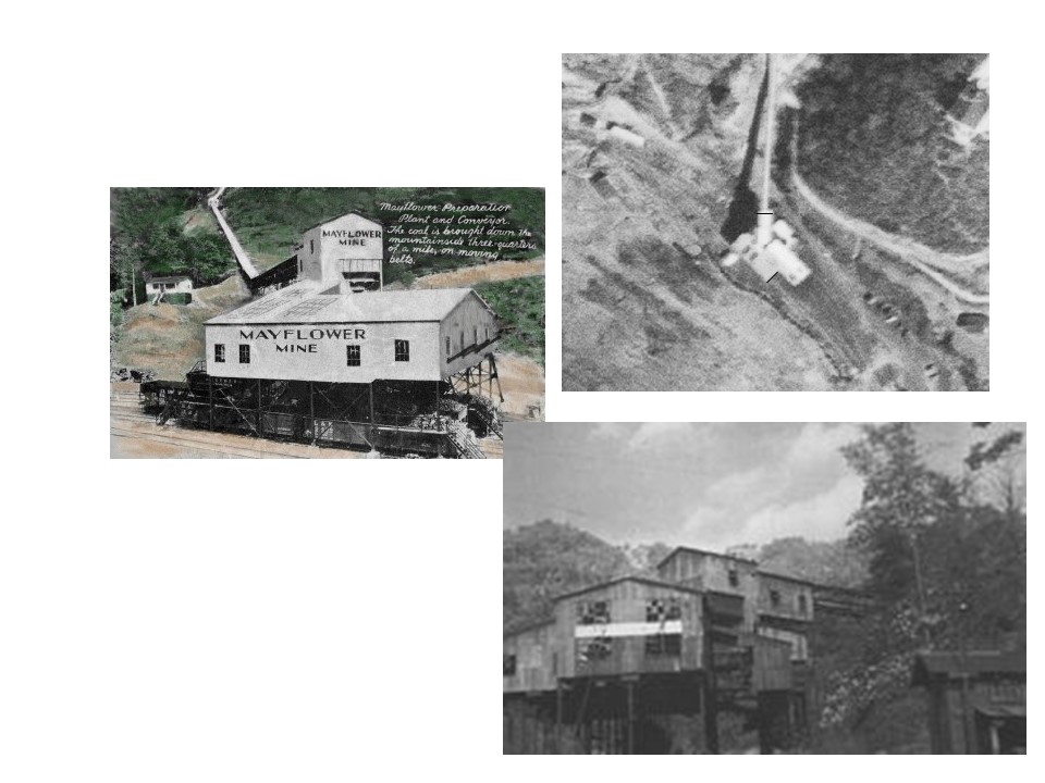
This is all of the photographic material I had from which to draw and build the Mayflower Tipple
Step 1 – Research. I’ve made a commitment to modeling the tipples as closely as possible (rule: no Walthers New River Mine allowed–it’s not a bad kit; it’s just over-used and too recognizable). The trouble is this area is not well documented by photos, so there’s a lot of guesswork and extrapolation involved. The first resource I had was a track chart that showed four tracks under the tipple, a medium-sized operation. Next, I found an aerial photo from the 1960s that showed the basic footprint of the tipple and the distinctive portion of the tipple connecting the tipple to the mine that sits 45 degrees to the tracks. Finally, I found a single grainy photo of the front of the tipple and a painting of it from a post card that someone had posted to Pinterest. With these resources, I had enough to rough-out a drawing.
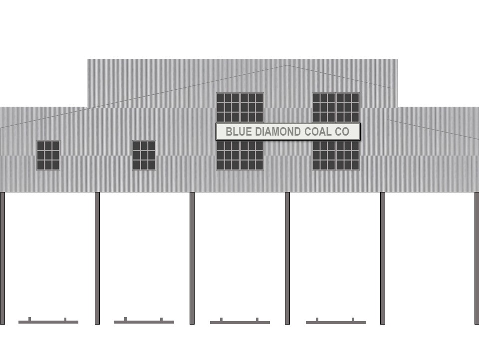
Step 2 – “Scale” Drawing. Regardless of whether or not I’m building a mock-up or the final model, I need some sort of scale drawing to build from, and for tipples that were one-of-a-kind, actual drawings are very rare. I use the word “scale” here loosely because none of the research offered any clear dimensions. Still, distances between tracks and height above hoppers can be estimated, so I did my best. To make the drawing, I used my favorite drawing program, MS PowerPoint. No, PowerPoint isn’t designed for this, but it’s easy to use, and you can draw lines to specific dimensions and angles. I would work on one side, matching it as best I could to the photos. Then I’d copy relevant bits from the one side to use as size references for the next side until all the parts were drawn. Some sides were longer than a piece of paper, so I drew these as two separate drawings I could glue together later. The tricky part was the photo and postcard showed two different time periods for the tipple. The photo showed a section added to the front over two tracks, so I had to figure out how this might have worked in concert with the tipple represented in the postcard.
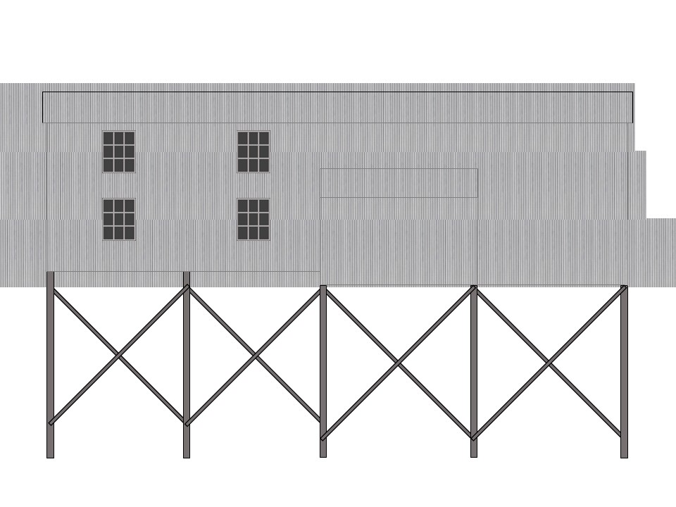
Line drawing of the front of the tipple showing the 2″ track spacing and profile
I decided to draw windows and corrugated metal siding on it as well. This was a simple matter of making a generic window and copy/paste it in place. The siding was just a texture I found online and copied into scale sheets to place behind the drawing (use the “send to back” function on right click). When everything looked decent, I printed it out.
Step 3 – Building the Mock-Up. For material, I used black-on-black 1/4″ foam core picked up at the local big box hobby store. It’s easy to cut and work with and has enough rigidity to make a durable structure. I cut out pieces of the drawing and then glued them to the foam core using normal white glue. Where I have a corner, I needed to pick one wall to recess the width of the foam core so they won’t overlap (i.e., when gluing the drawing would overhang the foam core by one foam core width). As you can see from pictures, the glue caused a little discoloration and warping of the paper, but hey, it’s a mock-up. Next I cut along the edges using a metal ruler and X-Acto blade. The trickest part by far was cutting the intricate frames of the leg pieces (5 total). A mock-up doesn’t really require this level of detail, but I decided it was important enough to judging the look of the tipple that I spent an extra 3 hours or so cutting these out. The glue and paper caused some of the sides to bow a little, so for these I cut out 1/2″ wide strips of foam core to attach perpendicular along the back and bring them back into shape and provide lateral strength. This required laying a heavy book on top while it dried, but it worked well.
Tipple mock-up in progress–I worked one joint at a time
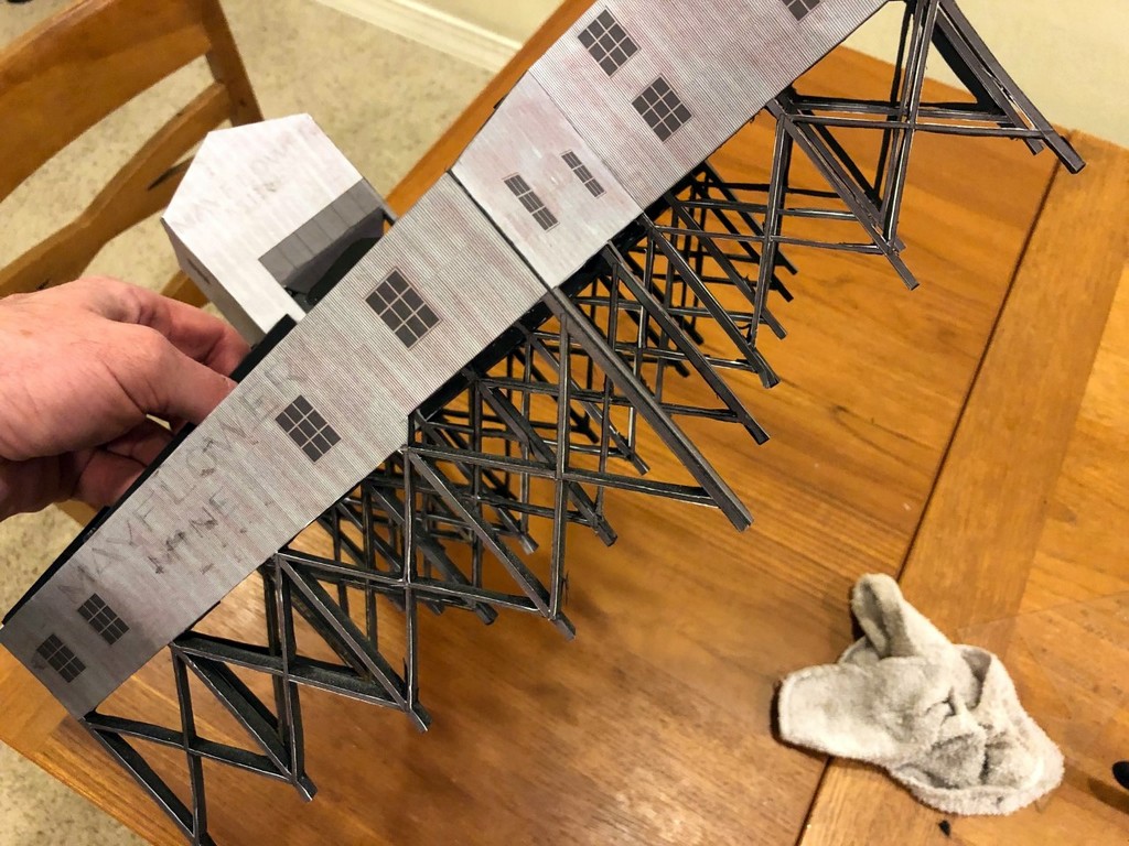
With the pieces cut out and strengthened, I started gluing them together. I worked on one corner at a time and used little pieces of square foam core to keep the corners square. I added structural pieces of foam core wherever needed to keep things sturdy. Again, the trick was to work one joint at a time (no more than two) instead of trying to build it all at once. The glue dried sufficiently in about 30 min, so I’d just come by every 30-60 min and glue another side on. Finally, I made the roof out of corrugated cardboard salvaged from a box–it’s a little thinner than the foam core but still has sufficient rigidity. After test fitting the roof pieces and making adjustments with the blade, I glued on the roof pieces–this is tricky because you have to worry about a lot of edges at once.
Step 4 – Evaluating the Scene. With the Mayflower Tipple mock-up complete, I could now mock-up the scene on the layout and see where the tracks would go, how tight the spacing would be for hoppers (adequate), how far I could bring it out or push it back in the scene, how much space I would have with the upper deck, etc. As it turns out, the tipple fits perfectly and doesn’t need any adjustment, but it would be easy to make cuts and repairs to the mock-up to try different things that would be a lot tougher to do on a final model. Any changes would simply be added to the drawing to use for the final model.
Conclusion. While I could have been halfway done with a permanent model in the time I built this mock-up, I now have the confidence in my drawing and in the scene to build the final model. Besides, it will be a while before construction on the upper deck in this area will be complete enough to install a permanent model, so in the meantime, the mock-up will give me and other crew members a good stand-in to enhance operations that I don’t mind getting a little roughed up. Beats having to use your imagination when switching out empty and loaded hoppers!
This is all of the photographic material I had from which to draw and build the Mayflower Tipple
Line drawing of the front of the tipple showing the 2″ track spacing and profile
Example of a portion of the tipple drawing from the side showing the bracing
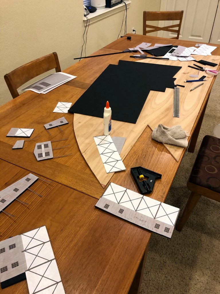
View of my messy workspace for building the mock-up showing foam core, cutting board, tools, and some finished pieces
Tipple mock-up in progress–I worked one joint at a time
Cutting around the leg pieces was by far the most difficult part of building this mock-up
Good look at the final model before the final step of adding the roof–it’s pretty simple with just enough pieces inside to make it structurally sound
The final tipple mock-up in place on the layout showing its size relative to the benchwork and hoppers
I haven’t added an update for a while because the layout doesn’t really look any different. That’s not to say I haven’t been working, it’s just been all the boring stuff – wiring. It may be boring, but if you want your layout to run well, it’s doggone important, so it shouldn’t be left as an afterthought.
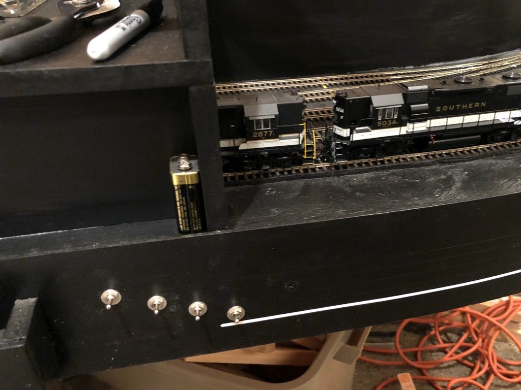
First, I corrected an issue I first noticed when running trains around the staging level – sound! I never ran sound locomotives on my previous layout, and now that I’ve got a few, I noticed how annoying it is to have diesels sitting in staging making idling noises that are easily heard throughout the room. These trains are supposed to be dozens of miles away, and I don’t want to hear them while they’re in staging. Of course, there’s the option to “mute” a sound locomotive temporarily, but I don’t want to force operators to go through an entire consist muting and unmuting every time they pick up or drop off a train in staging (and every time a short occurred, all the sound would come right back on anyway). For a solution, I went “back to the future.”
I installed a small SPST toggle switch (picked up 20 for cheap on eBay) for each staging or locomotive track (9 total) on the fascia where the track diagram will be. Unfortunately, this meant pulling dozens of feeders from the staging tracks and running a secondary bus for one rail under each track that’s connected to the switch. Thankfully this didn’t involve any de-soldering because all my feeders are connected via wire nuts. Now I can turn off the power to any staging track with sound locomotives until they’re needed, and all the operator has to do is flip a single switch. Old school “electrical block” solution to a DCC problem.
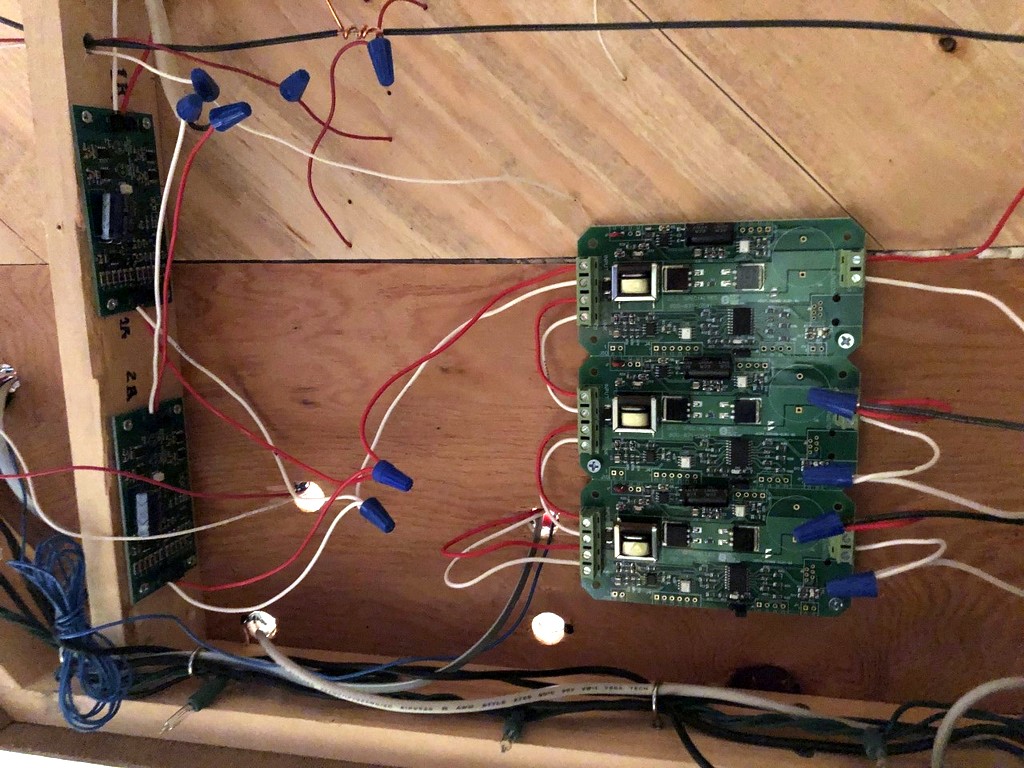
While I was at it, I broke down and ordered a DCC Specialties PSX-4 solid-state circuit breaker to go with my On-Guard-AR auto-reversing circuit breakers. I’ve been planning to do this all along and wiring for multiple zones, but after reading through the PSX documentation, I discovered my understanding of the PSX-4 and how it interacts with AR breakers was a little lacking. I didn’t know that the AR breakers should not be wired off a PSX zone but directly wired to the booster themselves. Turns out with the two reversing zones already protected by an AR circuit breaker, I really only needed a PSX-3 because I only have one non-reversing zone per level (1=staging, 2=lower level, 3=upper level, 1R=staging reverse tracks, 2R=St Charles wye to Mayflower). “Snap” – “hey look, now I have a PSX-3 and a spare PSX-1”. . . smart DCC Specialties! Not gonna lie, it was a little confusing to program the PSX to work well with the AR breakers using the Digitrax Zephyr, but I finally figured it out:
Set the Digitrax booster to .5 sec short circuit trip using booster instructions (CV 18 to “c” on my DCS100)
Solder the Digitrax jumper on each PSX zone per PSX instructions
Set the PSX to programming mode via the jumper per the PSX instructions
Ignore the part about setting the PSX address unless you need the PSX to respond to “on/off” or other special commands from the DCC (If you just need it to be a circuit breaker, you don’t)
Connect a single PSX zone directly to the Track A / Track B from the Zephyr
Turn the track power on on the Zephyr
Put the Zephyr into “OPS Programming” mode
Select CV55 (“CV”, “55”, “CV”)
Press “1” and “CV-W” (add delay to the PSX so the AR zones will trip/reverse first)
Select CV65 (“CV”, “65”, “CV”)
Press “80” and “CV-W” (set delay to 10ms which works for my setup)
If Zephyr shows “Busy,” exit programming mode and try CV65 steps again
Set PSX to ops mode via the jumper per the PSX instructions
Repeat steps for additional PSX zones
I encourage you to read all the instructions first and choose your own adventure–just sharing what worked for me.
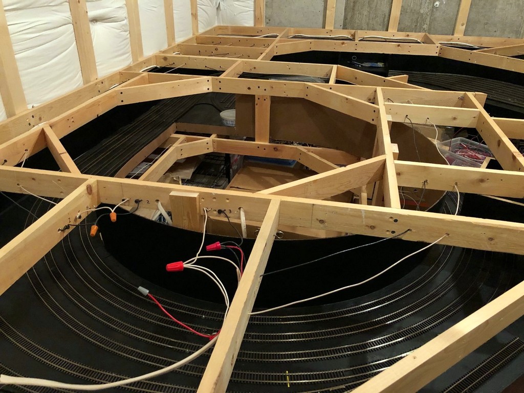
Finally, before I lay subroadbed and track for the lower level, I had to add the wiring bus, or in this case, two wiring buses. Two are needed because the St. Charles wye needs a reversing circuit, and the reversing district carries over all the way to Mayflower. Lots of drilling holes, cutting open Romex, and pulling heavy gauge wire through. I still have to make the little pigtails for feeders, but it’s mostly done. Shouldn’t be long before I’m laying track on the main level!
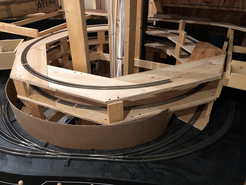
Just one more 1/2 turn to go before reaching the main level
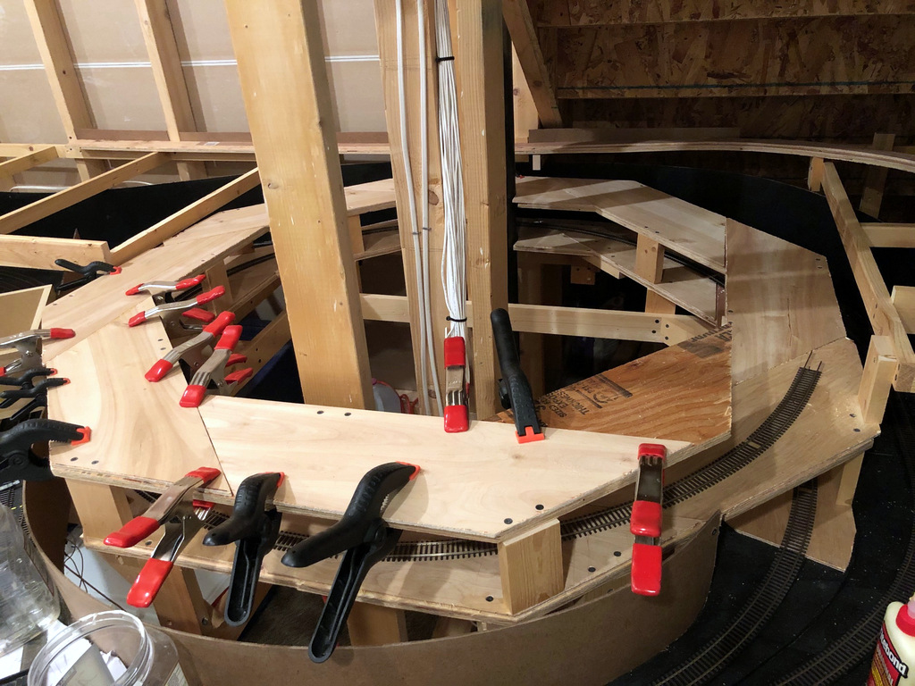
Just [almost] finished the first helix. Man, am I glad not to have to work around a floating wall for the second one! As promised, I’ve written an article on how to design and build a helix that’s strong, reliable, easy to build and an efficient use of space and material–it’s a design I call the “Double Pinwheel Helix.” I’ve built two helices this way now, and I haven’t seen another design that comes anywhere close to being this simple to build using nothing but plywood and a circular saw (no jigsawing for hours), and it’s very forgiving if you don’t cut the pieces exact or your space is a little wonky.
Rather than post it here, I put the article on Appalachian Railroad Modeling where more people would be able to find it and hopefully be inspired to overcome their fear of building a helix. You can find the article here. Here are a couple of photos so you can see the progress.
The key to the double pinwheel design is lots of clamps to ensure the lamination of pieces is thorough
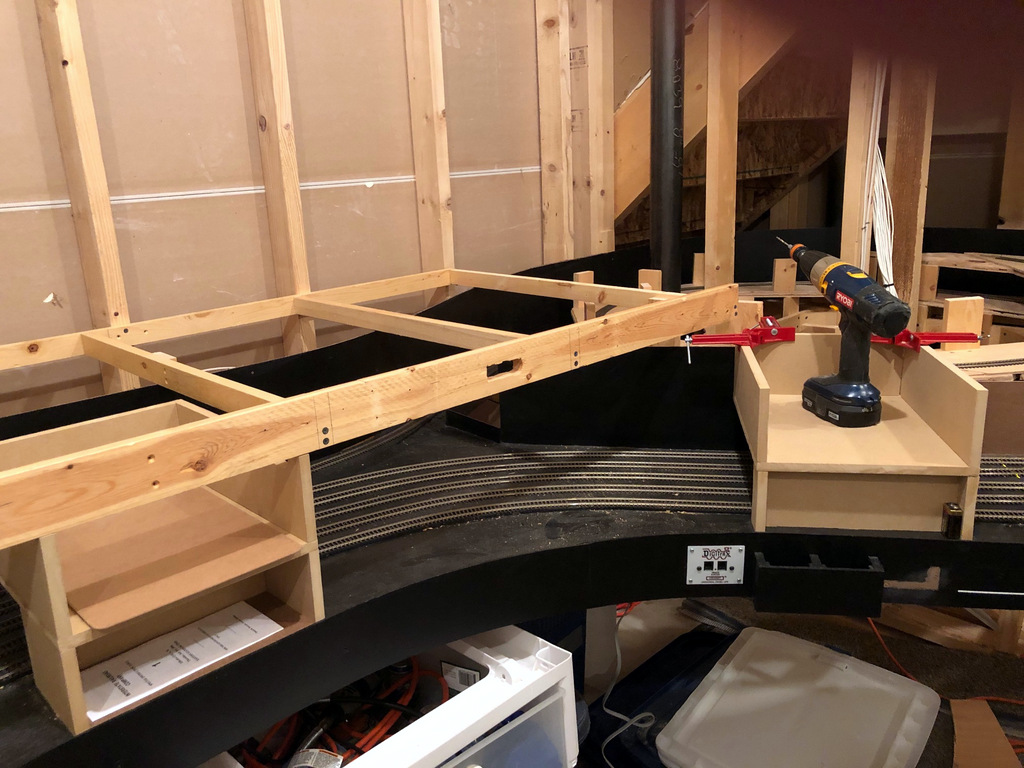
My undergrad is in Human Factors Engineering, the science of designing things so people can use them easily and intuitively. Though I’ve never been a Human Factors Engineer in my work, I enjoy applying the principles I learned to my model railroad. The first step of human factors for a layout is usually the space for operators–designing aisles wide enough to accommodate your people and give them access to the areas of the layout they’ll need. The next step is figuring out what other needs for space they’ll have while operating. One of those space needs is a place to store their “stuff” they use while operating–enter the fascia pocket!
I’m continuing my practices from my former Interstate RR layout. Upon being assigned a train, each operator will be given a clipboard with their train information (location, engine number(s), throttle assignment, etc.), instructions on how to work the train, any applicable train orders, a map/diagram of the layout, a switchlist, a pencil, and a decoupling tool. The operator will need this clipboard throughout the session, and since I DON’T want operators setting their clipboard on top of the layout, it’s important I design in convenient spaces for these clipboards.
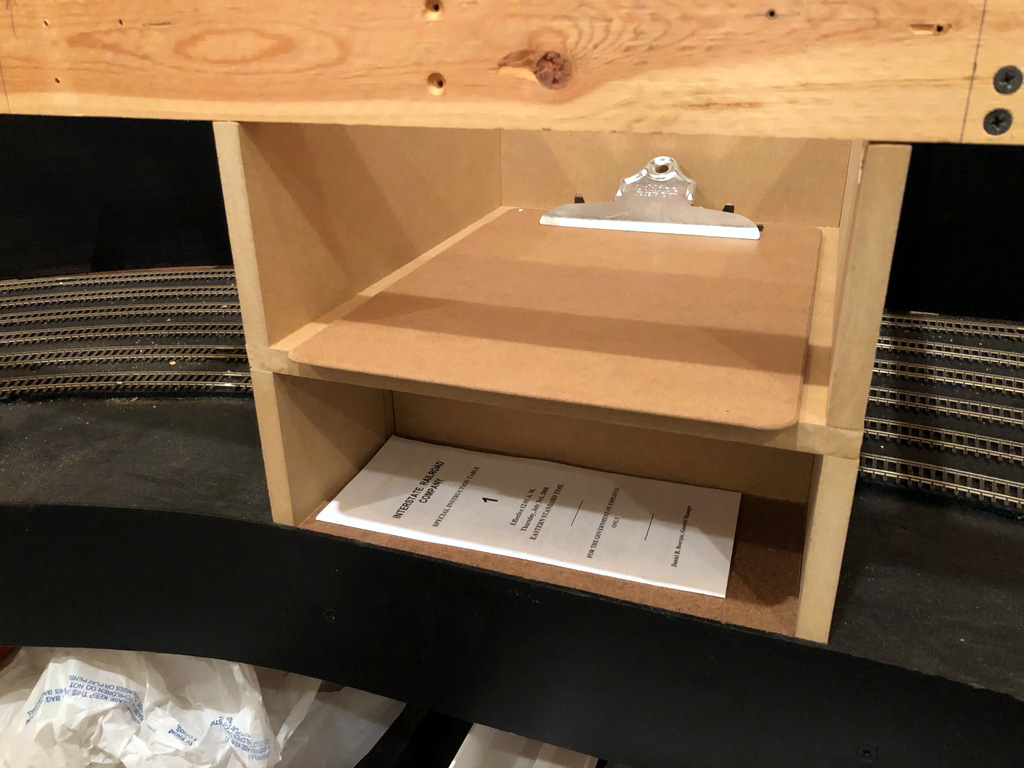
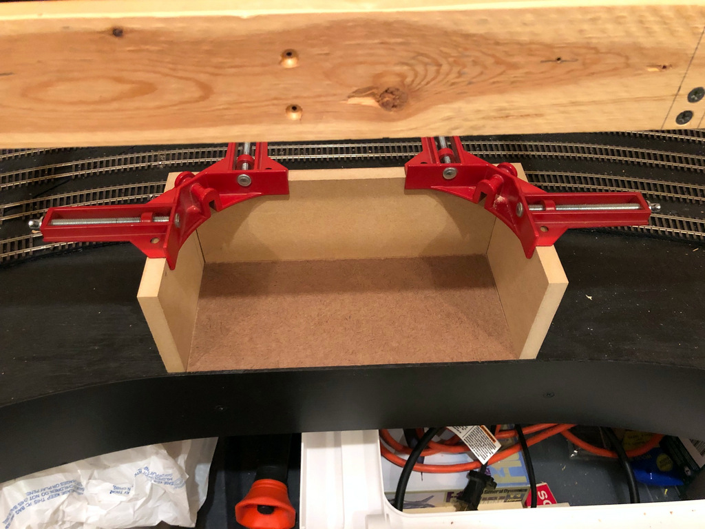
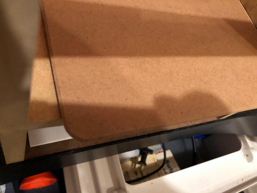
This is what a nearly finished pocket (still missing paint) looks like–this one will store a clipboard up top and timetables or switchlists below
Once I put in the first section of main-level benchwork above the staging level, I had a nice ~8.5″ space between levels that might work for this purpose, but I needed some way to keep the staging tracks safe. I decided to build clipboard pockets over the staging tracks since trains only need about 3.5″ of the 8.5″ for clearance. The clipboards are 9″ wide and 13″ long, so I’m making each clipboard pocket 10″ wide and 12.5″ deep–this will ensure the clipboard sticks out about 1/2″, just enough to ensure the clipboard is easy to grab without impeding on the aisle or snagging on operators.
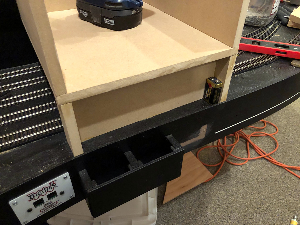
To support each pocket, I need a base about 3.75″ tall between the staging base and the pocket. I’m using these as storage pockets for useful things for operators as well. The pocket depth depends on how far the staging tracks are set back from the fascia. In some areas, I can make pockets 12″ deep for papers. In other areas, I can make pockets 4.5″ deep to hold extra switch lists, timetables or hand-outs. Some areas where the track is close only allow a ~1″ pocket. . . hmm. . . I know, that’s perfect for storing extra 9V batteries for the wireless throttles!
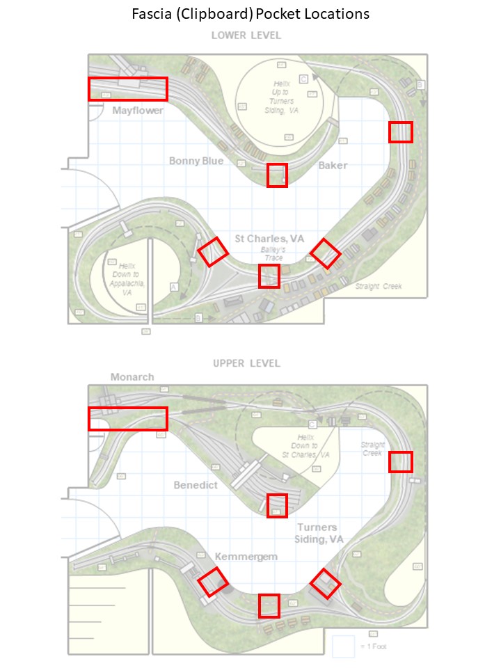
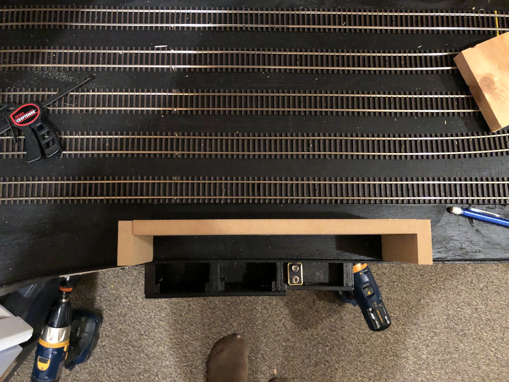
The next step was figuring out where to put them. I wanted them in spots useful for operators, but they also needed to be away from the yard ladders in staging and spread apart enough to allow easy access to all staging areas. I decided on five locations that line up well with the action on both decks. A sixth area is formed by a counter top a few inches under the benchwork for Mayflower. There will be a pocket within 2-3 feet of an operator for about 90% of the layout.
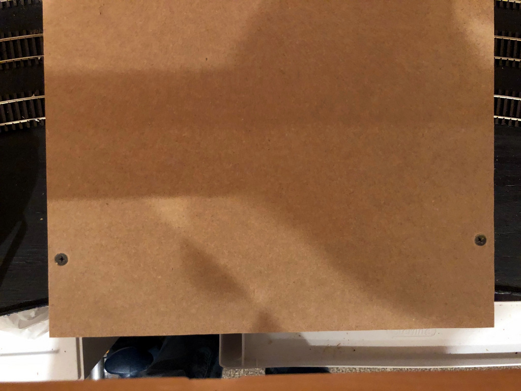
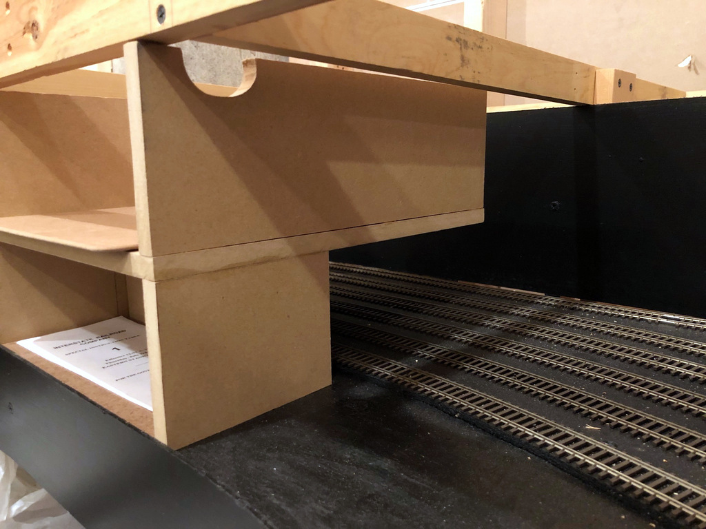
Overview of two pockets showing the ample space between them for accessing staging
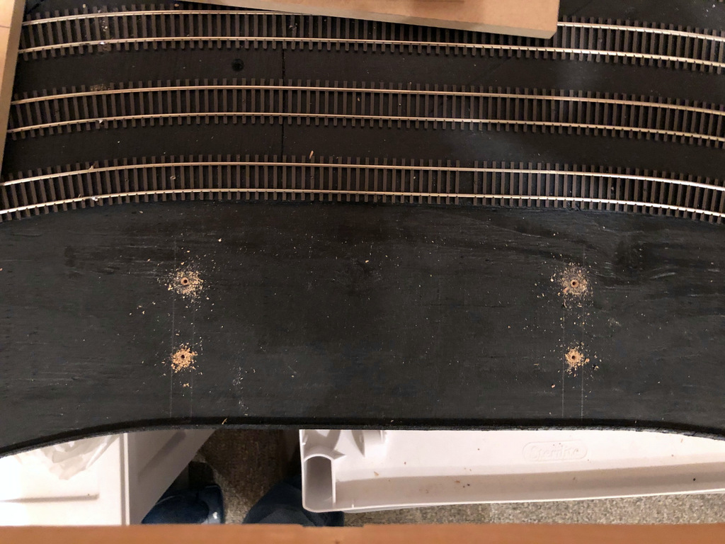
I made my pockets from 1/2″ MDF–strong and smooth. To secure the base to the staging level, I mock fit it in place, drew an outline, and used the outline to drill pilot holes through the subroadbed. After gluing the base pieces in place, I went back and drilled up through these holes into the MDF to lock it in place. Next, I secured the deck for the clipboard pocket to the base using glue and countersunk screws since the back would be suspended over the staging tracks. Finally, I glued the side pieces on top of the clipboard deck to finish the pocket. While I could have made the side pieces solid and mounted the clipboard deck inside them, I figured this method would be more durable as there’s no way for the deck to break away from the sides.
These pockets are certainly nothing fancy or extraordinary, but I find its often the small, ordinary things that make a difference. In this case, I’m hoping the ability to easily find a space to put their “stuff” will make operating on this layout just a little more enjoyable and stress free.
Layout wiring on the St. Charles Branch is simple yet very robust using common household wiring supplies. First, I’ve divided the layout into six blocks: four “main” blocks (1. Staging, 2. St. Charles, 3. Mayflower, 4. Upper Deck), and two reversing sections (1R. Staging loop, 2R. St. Charles Wye). Even though I don’t have a power block distribution circuit yet (like a PSX4), I’m wiring the layout for that eventuality and just tying all the blocks together at the command station as an interim.
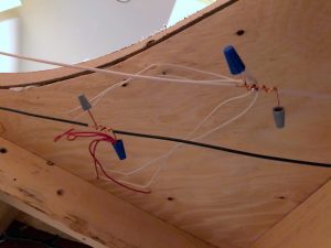
Feeders are connected to the wiring bus via wire nuts connected to pigtails along the bus.
The bus wiring for each block is copper Romex wiring. . . that’s right, Romex, the 14 AWG copper wire you use to wire household sockets and light fixtures. It’s overkill, but it’s easy to find, comes in long lengths, and the current loss for DCC applications is pretty much zero. I strip the outer sheathing, remove the bare ground wire, and use the black and white wires. I run them under the track through holes in the benchwork separated by about 2.5″. Lesson learned: if running the bus for two blocks side-by-side, make sure you label each about every other piece of wood to avoid cross-wiring blocks later.
I drop feeders at least every 5 feet, so on every 2-5 feet of bus wiring, I’ll strip off about 1″ of insulation and make a “pigtail” if you will using a length of 4″ of the bare copper wire (Romex ground wire) wrapped tighly around the bus core about 3 turns and soldered. I leave about 1″ of copper sticking off either end and cap it with a wire nut. I separate the pigtails for the white and black wires by about 4-6″ to avoid accidental contact of exposed wire.
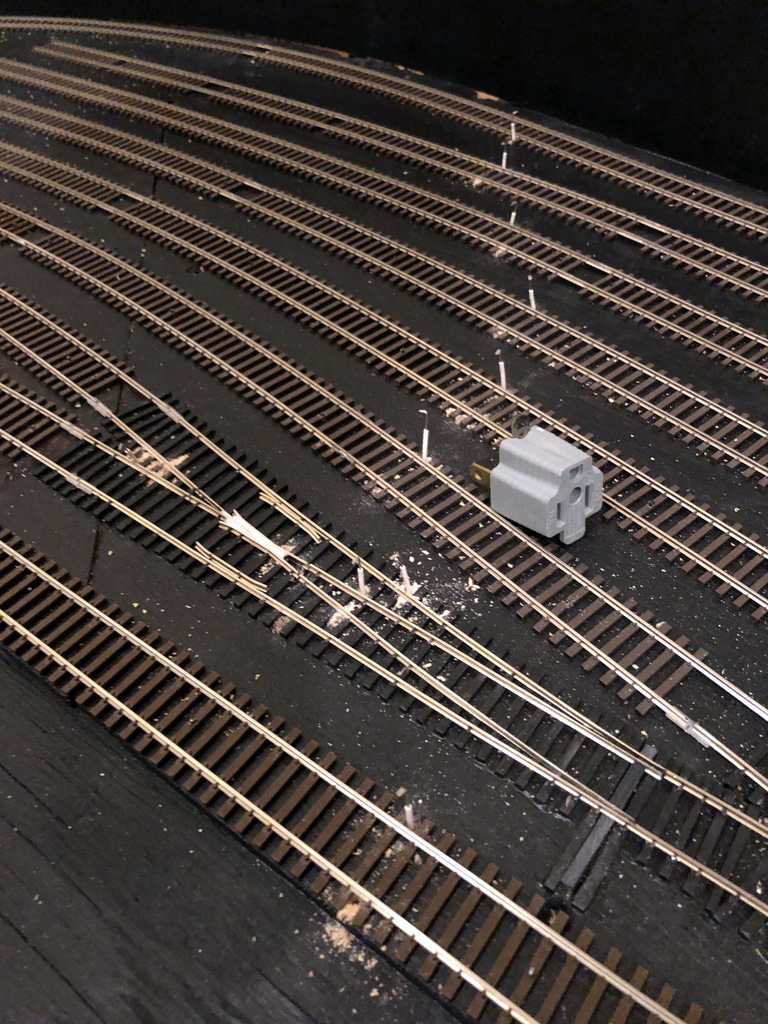
Wiring feeders from the rails to the bus under the layout. The gray plug marks the spot of connection to make it easy to cut wires to the right length.
Finally, the feeders. As mentioned, I try to drop them every 3-5 feet of rail. For bulletproof operation, every single rail on the layout is directly connected to the bus either through its own feeder or a single soldered joint to the rail next to it that’s connected to a feeder (no trusting rail joiners to carry current and signal). I drill the holes first, then drop pieces of 18 guage stranded wire through to connect to the bus. You’ll notice in the picture above the layout the little gray plug. I use this to mark the location of the pigtail under the layout so I can accurately cut the feeders to length, leaving about 1.5-2″ extra length to account for vertical distance through the subroadbed and some wiggle room for orienting the feeder to fit into the pigtail. Because I hand-lay my switches, I need a LOT of extra feeders for the point rails and frogs (connected to switches under the layout).
To make sure I hit all the holes, I leave the sawdust from drilling them in-place until all feeders are in. I also work one color at at time; white for one rail, red for the other. Once all the feeders of one color are in place, I’ll tin them with solder and solder each to the rail. Under the layout, I’ll gather together 2-3 feeders, twist them together, and tie them to the pigtail using a common wire nut (size depending on the number of wires being tied together). A little tug ensures they’re solidly in-place.
I’ve found this method creates rock-solid wiring that’s easy to modify and troubleshoot–just disconnect and reconnect the wire nuts as needed. This method also works perfectly with Digitrax DCC which prides itself on picking a slower data rate that works well with non-high-speed wiring. If using on a different system, I recommend doing some testing first.
I’m all about simple but effective solutions to construction challenges. One of those challenges is laying multiple tracks (like a yard) on a set spacing quickly. In my case, I have staging yards designed on 2″ spacing between track centers. There are several methods for spacing the tracks: I could just measure between them with a ruler every time I put in a nail, I could mark out spaces and draw a line for the edge of the next track, or I could make a really simple tool to make this process effortless.
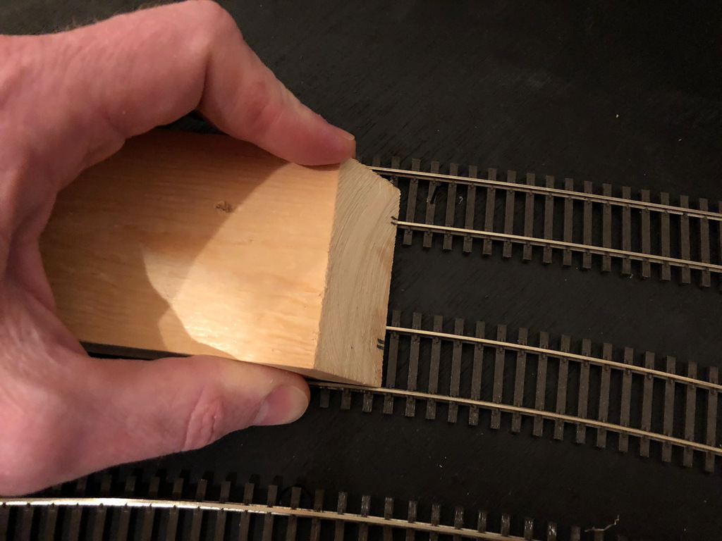
Enter my fancy homemade track spacing tool! It’s a piece of 1×3″ lumber about 4″ long and cut 45 degrees on one end. . . I literally pulled it out of my scrap pile. Using a combination square, I penciled in a mark exactly 2″ from the edge on the bottom of the 45 degree face, then drew a second mark one rail’s width in from the first (closer than 2″); then I repeated this from the other side so it can be used in either direction.
Track spacing tool for 2″ centers made from a piece of 1×3″ lumber and some pencil marks
To use the tool, put the first track into place and secure it. When it’s time to lay the second track, simply place the tool along the inside edge of the outer rail of the first track, move the second piece of track so the inside rail lines up with the pencil marks, and secure it. Move the tool down to the next spot, line up the second track, and secure it–too easy. I’ve found using the inner rail of the first track works better than a smaller spacer between outer rails, especially on curves.
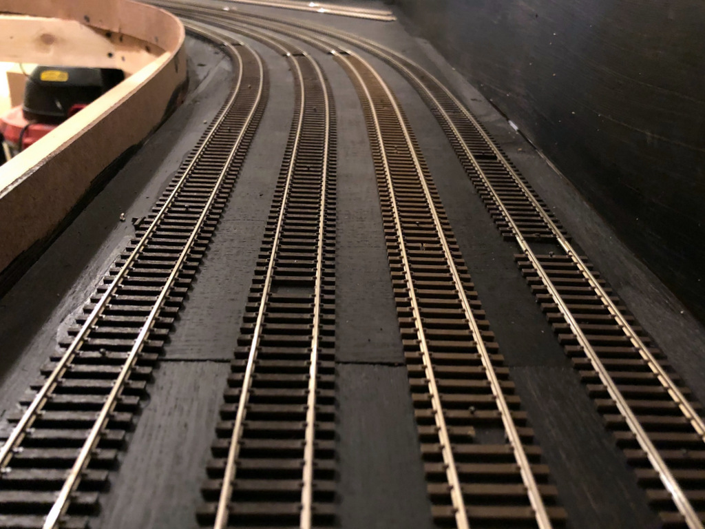
I’ve decided to stop modeling the Southern and model the Pennsy main instead. . . Nope, this is the Southern staging yard laid out using recycled Atlas code 83 flex track from my last layout and my handy dandy 2″ track spacing tool
You can make the tool work for whatever spacing you need just by using different marks and different sizes of lumber. It sure ain’t fancy, but it’s elegant in its simplicity.