


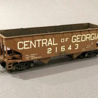
Finished HO-Scale 2-Bay Short-Taper Offset Hopper
HO-scale modelers are blessed with a lot of coal hopper models and kits to work with. One fairly common car that’s still tough to model is a 2-bay short-taper offset hopper. This car is distinct because of the smaller and more steep angles in the side sheets to get from the inside of the car to outside the ribs and the three thick rivet strips at the ends and center. This car was also longer than most 2-bay cars at 34′ versus the 33′ of a more common offset. Most people would be content to just use a 33′ car (and I don’t issue any judgment here), but I’m kind of a hopper nut, so…
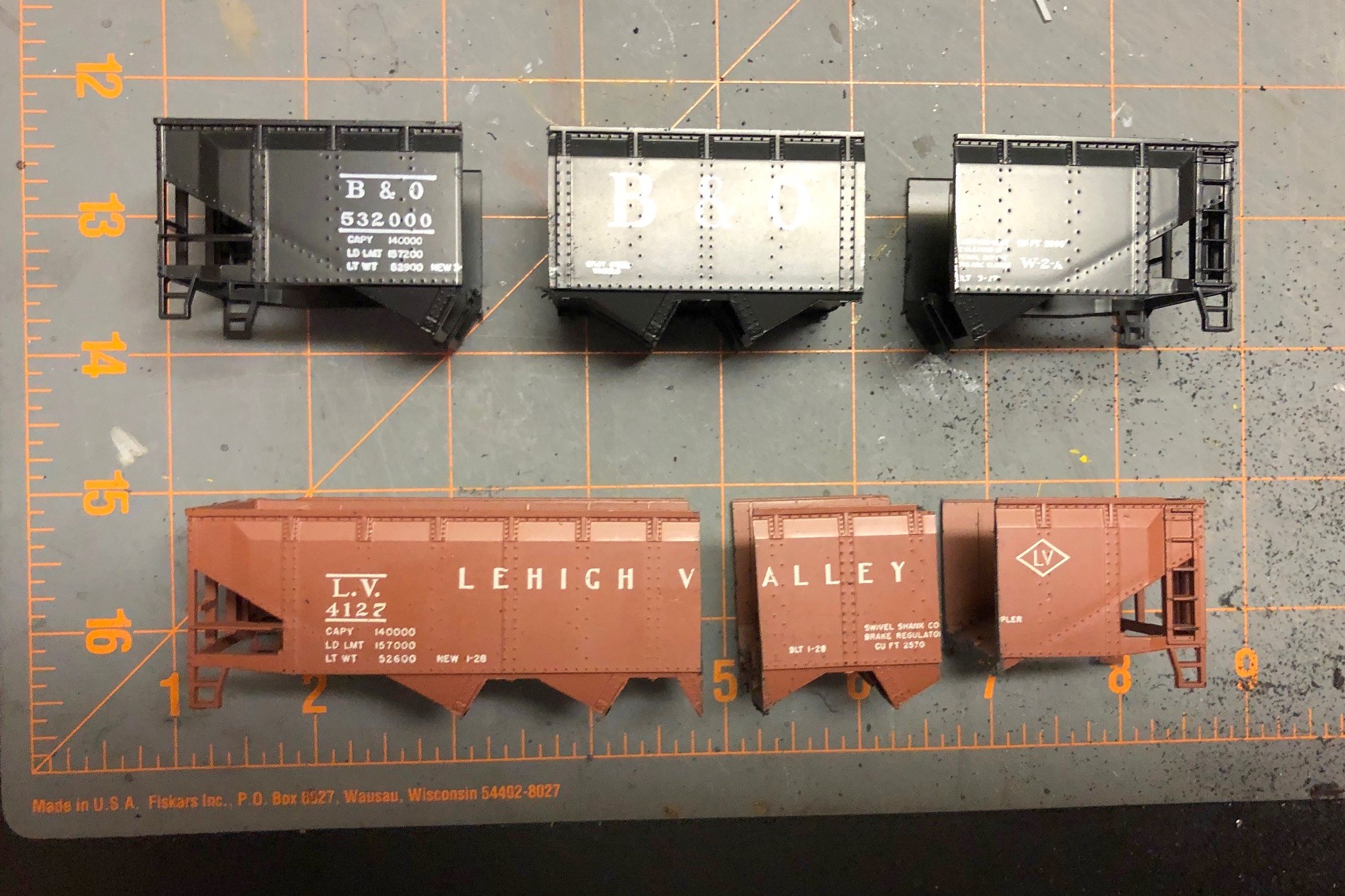
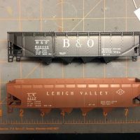
Athearn made an old blue-box kit for a 4-bay version of the short-taper which can still be found on eBay or at swap meets. The model has good overall dimensions for height and width, and the angles look good. Cutting down a quad hopper to make a twin sounds pretty straightforward. If you don’t care about having an extra rivet strip, it is! Of course, I had to care… sigh. There’s an extra rib between the rivet strips on the twin compared to the quad, so I had to figure out how to get the extra rib in there. Turns out, there’s just no way to do it with a single shell (or I wasn’t smart enough to figure it out), but it was possible using two shells–2 quad shells to make a 1 twin… makes sense, right? I guess technically I could make 2 twins with 3 shells, so I did keep the extra pieces in case the bug strikes again.
2. Cut hopper bodies
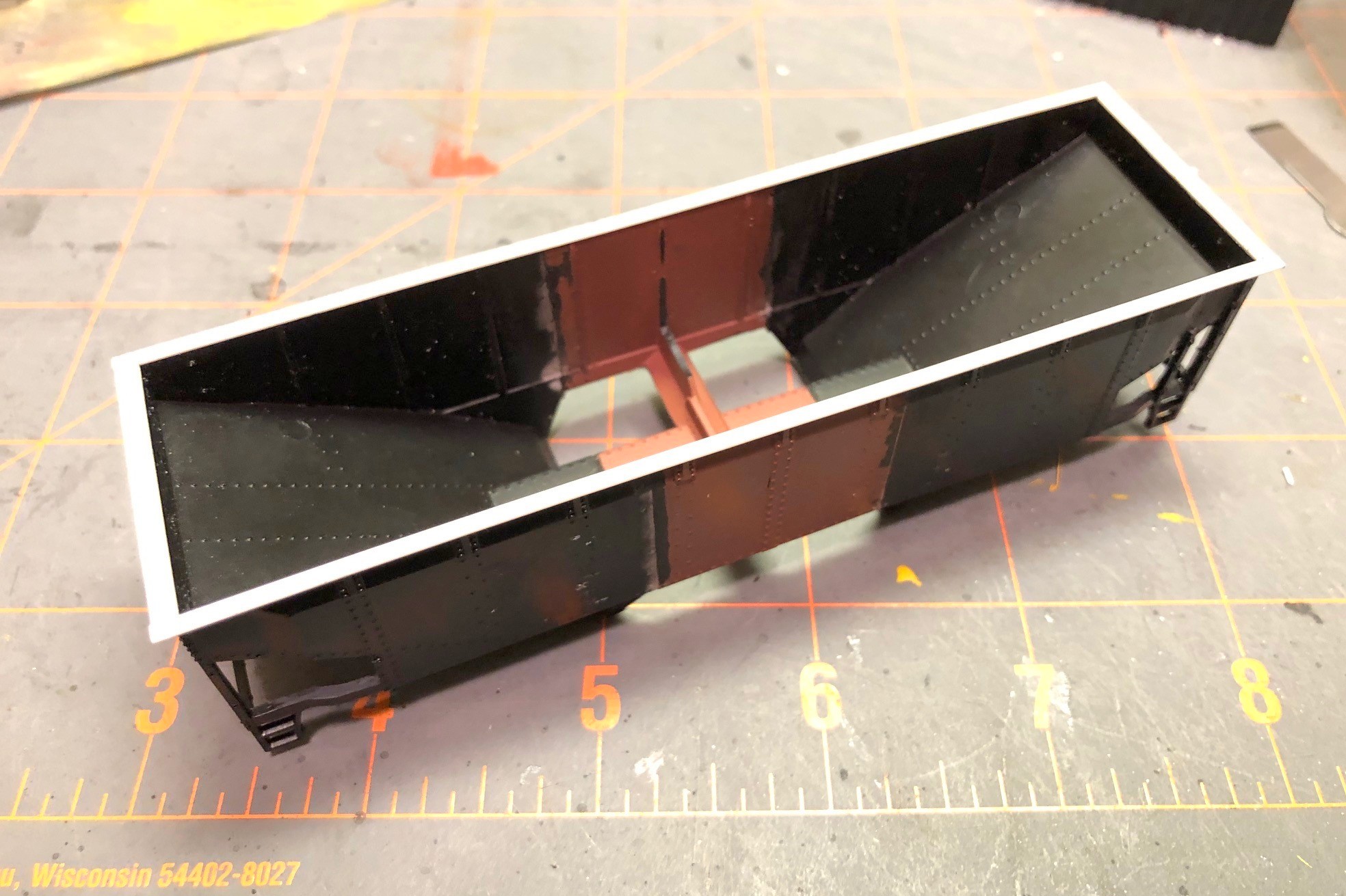
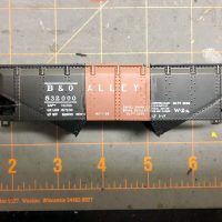
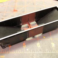
Picture 1 in the gallery shows the two original shells, and you can make out the pencil lines where the cuts need to be. I chose a spot between rivets to give myself a chance of saving the rivet detail in the putty and sanding step later. Using a razor saw, I cut each shell into three pieces as seen in picture 2 with the black hopper providing the ends and the red hopper providing the center. After cleaning the bays off what would become the center, I glued the ends to the new center piece as shown in picture 3. This step is the most critical of the whole project, and it took some filing to get everything square. I used plastic model cement to give myself time to line up the pieces–it’s crucial to get the sides aligned so they’re “level” across the gap. A gap is easy to fill and sand flat, but only if the sides are even with one another.
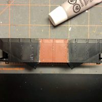
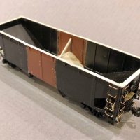
Once this new shell had dried thoroughly, I removed the top chord. The top chord on the original model is pretty chunky, and it would be easier to add a new one across the gap than try to fill every gap on top perfectly. It was pretty simple using a No 11 X-Acto blade swiped repeatedly under the top chord resulting in the shell seen in picture 4. Next, I filled the gaps with modeler’s putty. Using a combination of the back of an X-Acto blade and fine sandpaper, I was able to get the joint pretty smooth, and I was careful to stay away from the rivets as you can see in picture 5. This was also a good time to remove all the molded-on grabs with a combination of nippers and X-Acto blades. I found the corner posts and ladder posts to be really thick, so I whittled them down a little on the back side with an X-Acto. I also trimmed the top of the bottom sill near the ends to make it a consistent thickness instead of a taper like the model.
7. New styrene top chord
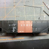
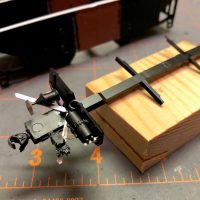
Next I worked on the center sill and undersides. First I cut the center out of a single underbody to shorten it to the right length and joined the ends together with glue. After it set, I used a large X-Acto chisel blade to remove some the material as shown in picture 6. I left a little strip to hold the hopper doors on. Next, I added a new top chord to the shell. I didn’t have the bag to verify, but I believe I used Evergreen HO scale 2×6 for the sides and 2×8 for the end to get to picture 7. I added four corner caps made from .010″ sheet styrene and rounded them on the top and on the corner after they dried using a file. Moving back to the underbody, I removed the existing mounting “blobs” for the brake gear, and in their place, I added angles from the bolster area to the corners using strip styrene (this was a pain, but I found if I cut them to the approximate shape, glued them with plastic cement, then press fit the underbody onto the shell and maneuvered the angles into position while the glue was still wet (I didn’t glue the underbody to the shell yet). When the angles had set, I added the brake parts including some brass wire for piping and a bracket for the reservoir made from sheet styrene as shown in picture 8.
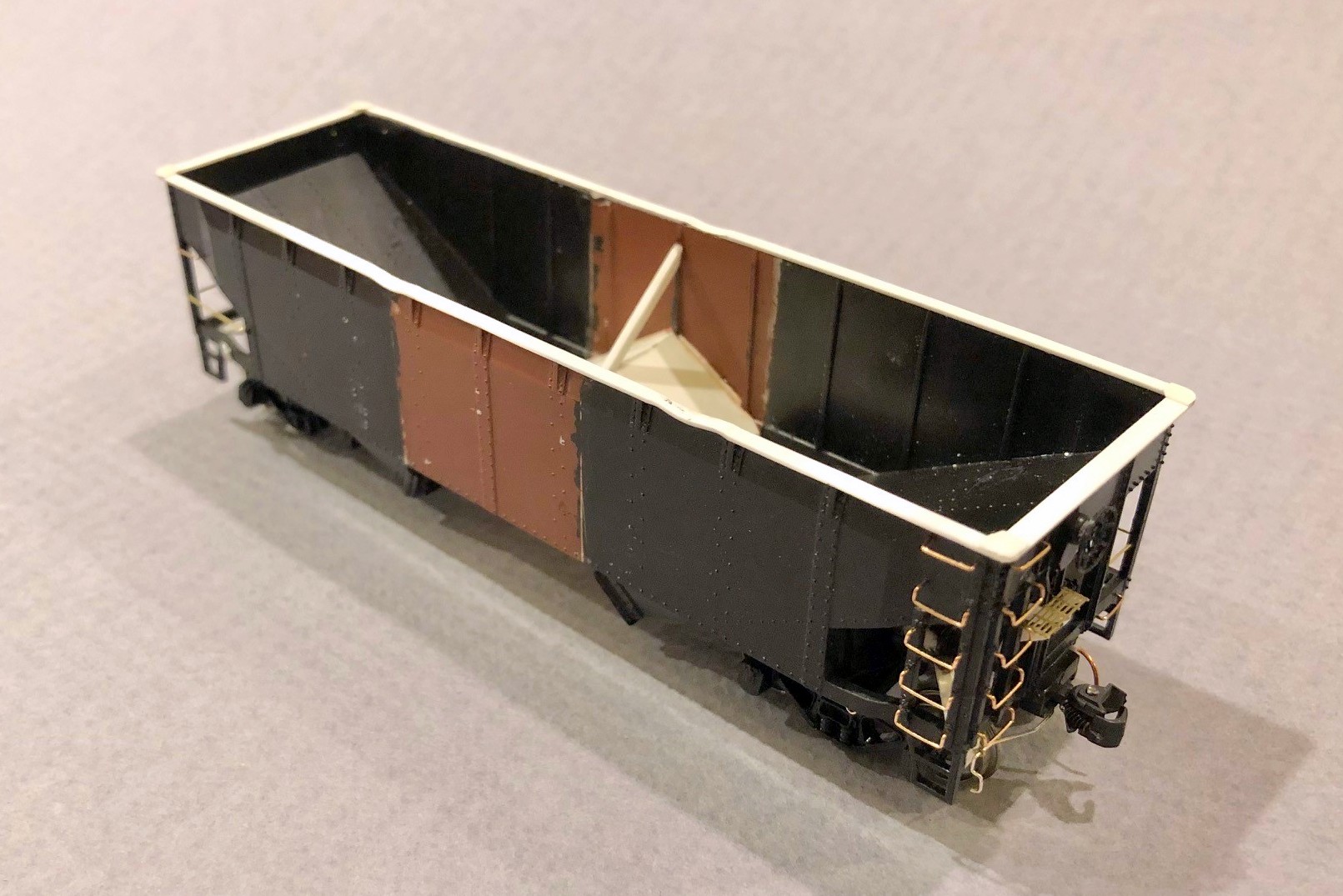
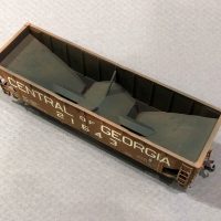
10. Finished interior
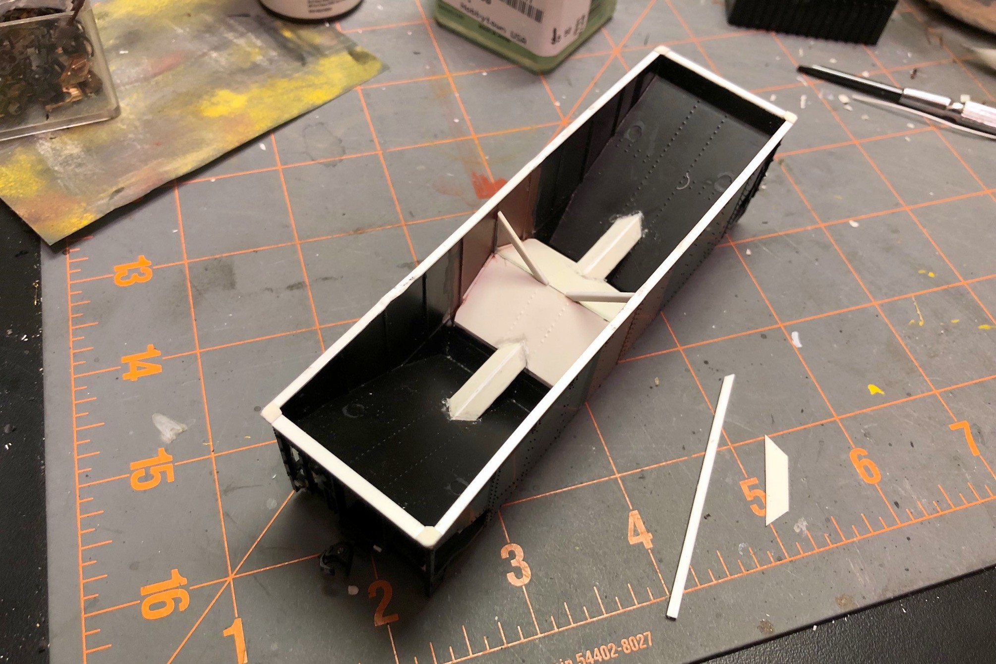
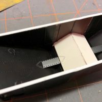
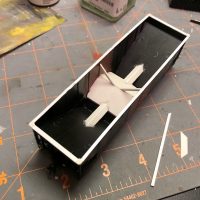
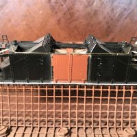
The interior of the car was challenging. I went ahead and glued the underbody and doors in place first, then added some styrene square rod above the doors to get it even with the model’s center sill piece. The new center slope sheets were cut from a single piece of styrene, and I used a pounce wheel to put some rivet lines into it to match the end slope sheets. Because of the ribs, the new slope sheet didn’t quite reach the sides, so I used bits of styrene to fill in the gap between ribs as seen in picture 9. Next came the not-so-fun part of turning the flat center sill ridge inside the car into a tapered one. I don’t have interior photos of one of these cars, but I can’t imagine using a flat top when you want the coal to exit the car. This step was not fun. Not one bit. Lot’s of measuring, cutting, folding, and taking back out and cutting again. My pieces ended up being too wide, but I just glued them on, let them set, then trimmed them to the width of the ridge in the shell with an X-Acto blade. Some styrene strips to make the angle braces and the interior was complete as seen in picture 10.
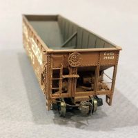
11. Final details added
Now I was ready for all the little details that you can see in picture 11. I drilled holes and installed all the grabs, making the long grabs on the non-ladder side from brass wire. I added coupler cut bars to a bracket made from styrene and an eye bolt. I made tow loops from brass wire, and I made a new brake platform from bits of styrene and some brass Apex roof walk material. I added the brake line along one side using brass wire and eye bolts. I added some tack boards from styrene on the bottom sill. I added train line hoses made from copper wire from old Cat 5 cable glued between two styrene angle bits (makes for an indestructible train line). A kept the molded on steps as I needed them to be durable for layout handling, but I used an X-Acto blade to shave them down a bit in the back to thin them out. Finally, I added a little buckling to the top chord using a 100W lightbulb held to the styrene for a few seconds and then pushed down using the handle of an X-Acto knife (be careful, the styrene melts really quickly). It was finally ready for paint (picture 12).
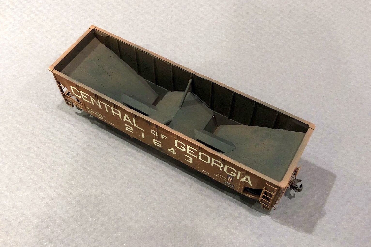
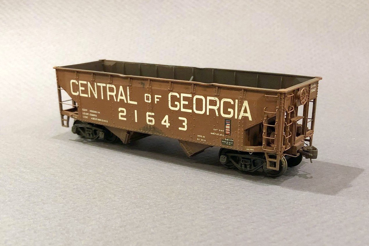
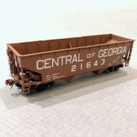
16. Final hopper – interior weathering
I first sprayed everything black, then gave it a couple coats of “burnt sienna” for the boxcar red. Because the paint was very flat, I sprayed it with a couple coats of Testors Glosscoat (rattle can) to prep it for decals. The K4 decals worked really well and had just about everything needed with the exception of an ACI label I stole from a Microscale data set. The K4 set looks like it’s designed for a 33′ car, and this prototype is a 34′ car. I ended up cutting the road name into “CENTRAL,” “OF” and “GEORGIA.” I place the end lettering first and then centered the “OF” between them, a little more spaced out than the decal sheet. I used about 800 applications of Micro Sol and Micro Set and pushed the decal firmly onto the body using a damp paper towel until everything was nice and snug over the rivets and on the body as seen in picture 13.
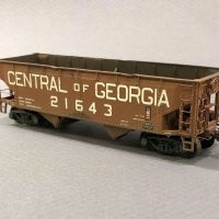
Weathering was a three step process. First, I dry brushed a little dark rust color both inside the hopper and in a few spots on the outside using a picture of this specific car as a guide. Next I gave it a couple of washes with very thinned black and then tan paint, wiping it off down the car (like rain streaks). Finally, I airbrushed some black inside the hopper and underneath followed by a couple coats of tan, hitting the trucks and hopper bays harder than the body to get the final model shown in pictures 14-17.
I’m very happy with how this project turned out, but I’m also very happy I don’t need a fleet of these cars. Many will look at this car on the layout as “just another offset hopper,” but I’ll always know the extra work that went into building a more accurate model of a neat prototype.
-
- 1. The two Athearn quad shells with pencil lines where the cuts will be made
-
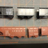
- 2. Cut hopper bodies
-
- 3. Hopper pieces glued together
-
- 4. Top chord removed
-
- 5. Joints puttied and sanded
-
- 6. Underbody modifications
-
- 7. New styrene top chord
-
- 8. Brake gear details
-
- 9. New center slope sheets
-
- 10. Finished interior
-
- 11. Final details added
-
- 12. Ready for paint
-
- 13. Painted and decaled
-
- CofGa 2-bay short-taper offset HO scale
-
- 15. Final weathered hopper, side 2
-
- 16. Final hopper – interior weathering
-
- 17. Final hopper – B-end detailing
That’s a really nice job of modeling, Dan. Well worth the time and effort — and the 800 applications of decal softener!
Dan, I also am very picky about my hopper car models. I have a picture of a war time hopper the side of it is like the Accurail composite two bay but this car is a four bay car I have never seen one. The photo is such that you cannot make out any reporting marks , Have you seen any 4-bay composite cars? Mike
Mike, I haven’t seen any 4-bay composites. I’m curious, though, so if you’re able to send the picture (or a link) to my email in the “Contact” tab above, I’d appreciate it!