


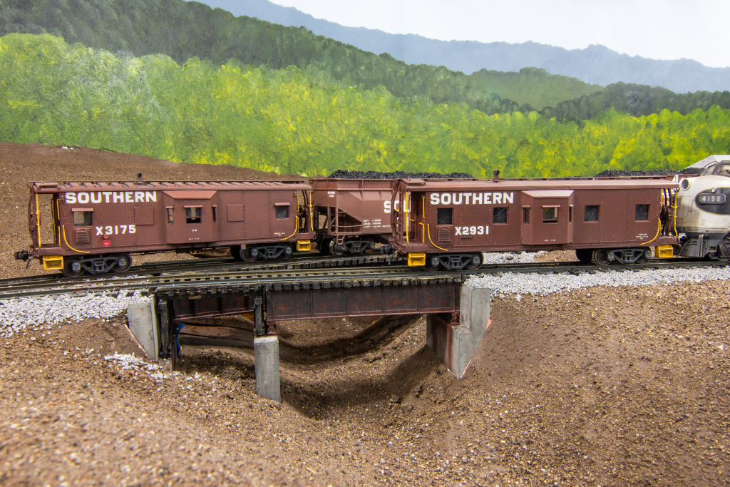
Two Southern cabs in service in the coal fields pass on the short bridge across Bailey’s Trace
In Part 1 of this 4-part series, I showed the modifications required for the body, windows, and steps. In part 2, I’ll dive into the roofs, bay windows, and underbody.
Roofs
- Pressed panel roof (option 1). The “two-bulge” roof panel seems to have been less popular than the smooth roof, but I found at least a few examples that made me want to model it. As mentioned in part 1, this is a tough roof to find, and the only example I had from a Milwaukee Road horizontal rib boxcar kit was too wide. I decided it wouldn’t be too tough to model from styrene bits. From part 1, the roof was already smooth except for the panel separation pieces. The roof was still a little short, though, so I added a piece of .060″ styrene to each end, lined up with the bottom of the roof. Once the glue dried overnight, I used X-Acto blades, a flat file, and sandpaper to shape the top of the new piece to the contour of the roof, and I made sure the roofwalk holes were filled and smooth. Once this was complete, I filled in the gap with modeler’s putty and sanded it to make it seamless. To create the pressed bulges, I used some .125″ half-round strip styrene (Evergreen 244). I cut 18 pieces to the exact width of the roof using a NWSL Chopper II. I then used an X-Acto chisel blade to cut a steep angle on each side of one piece that looked about right, and I ran both the top and bottom of this piece over a flat file to make it lay a little flatter and give it a flat top. This first piece became my “master,” and I did the same treatment to the remaining 17 pieces. Next, I marked the exact middle of the underside, set it over a metal straightedge along the line, and carefully and slowly bent the piece until it matched the contour of the roof and stayed in place easily. I then used liquid model cement to glue all the pieces in place. They sit two per panel and are evenly spaced across the roof (i.e., same distance between them both within a single panel and across panel lines) except for the end panels. When I originally installed these, I felt they still sat a little tall, so I went back with a flat file and took more off the top–I ended up accidentally removing portions of the roofwalk supports, so this is much better done before installing them. I filed the roofwalk supports to get them flat on top again and rebuilt the tops with strips of .015 x .020″ styrene. Finally, I used a little modeler’s putty and some sandpaper along the outside edges of the pieces to blend them into the curved edges of the roof. One final step was adding a strip of .015 x .020″ styrene to the edge of the roof on both sides–I had missed this initially but added it before painting. Of note, I didn’t realize until after my roof was in place that one of the raised panels where the smokestack goes is shorter (the smokestack goes onto flat roof), so I had to fix this later–better to get it right when you install the roof.
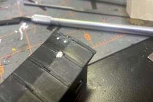
17. I added a roof extension from .060″ styrene
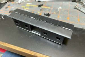
18. I used modeler’s putty and fine sandpaper to eliminate the gap and make the end panels smooth

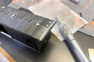
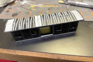
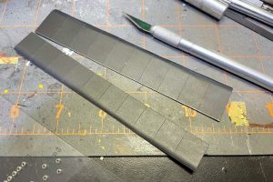
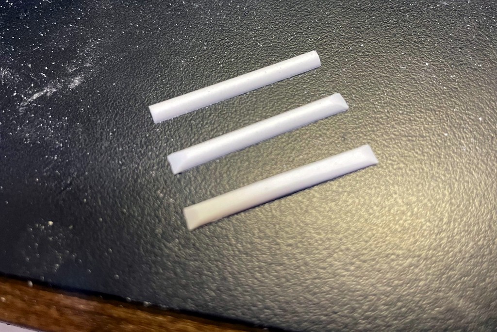
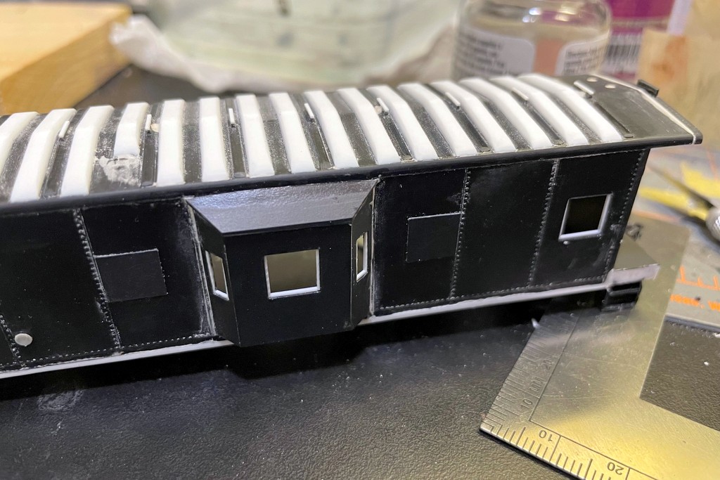
19. The raised panel ribs were made individually from half-round styrene cut and filed to shape
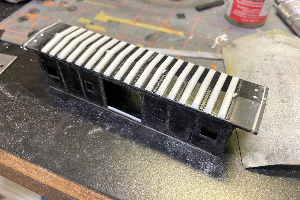
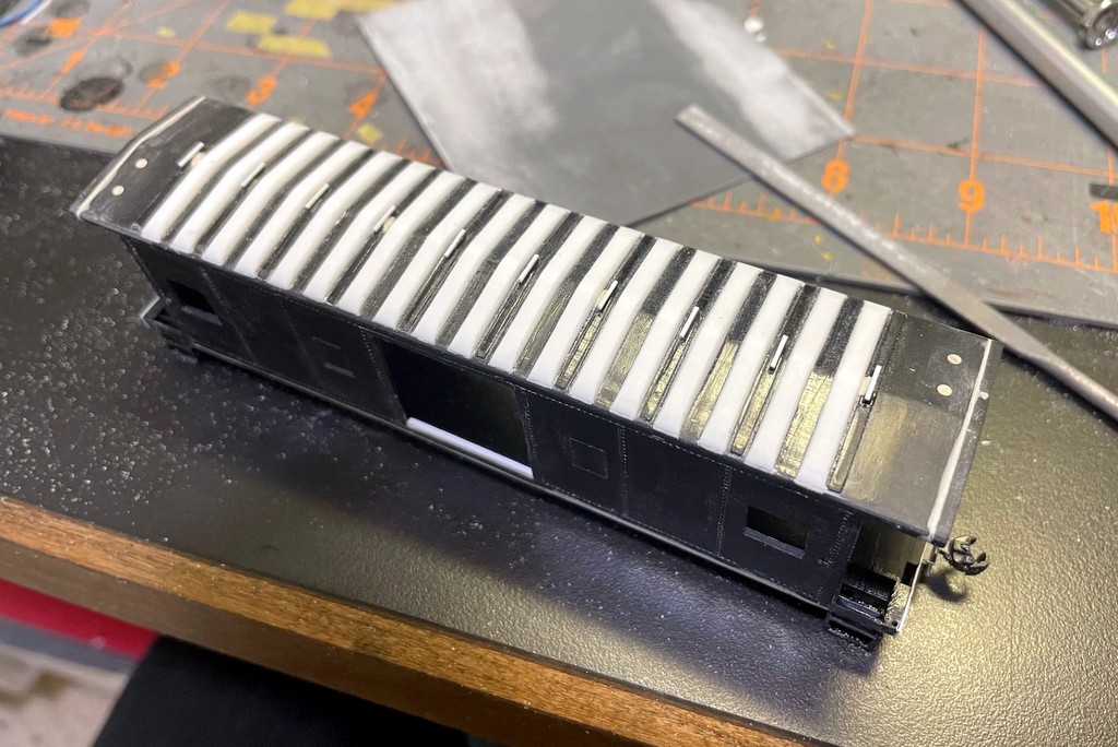
20. After bending to match the roof contour, I glued the ribs in place evenly spaced across the roof

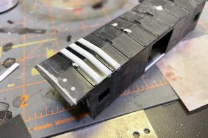
21. All ribs now in place

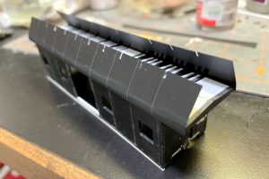
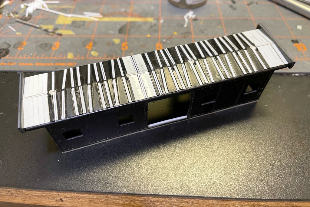
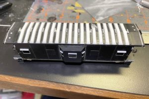
22. Finished roof with some additional filing and putty to smooth the edges
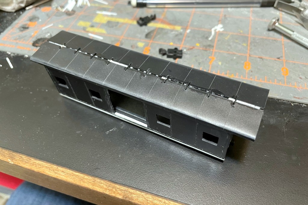
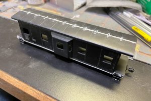
- Round roof (option 2). The round roof was more popular on Southern cabs of the ’40s-’60s. It’s a wholly different process to model it than the pressed roof, but in my opinion it’s a little easier and less time consuming. I started by adding .060″ styrene sheet to the ends to extend the roof with the bottom matching the bottom of the existing roof. I waited to cut and file it down, though. The next step was gluing a bunch of .015 x .080″ and .015 x .020″ styrene strip into the low spots between the raised pieces of the existing roof to form a good foundation for the new roof. Once these were dry, I used a flat file to knock down any high spots (the raised panels are higher in the middle of the body) and to shape the end extensions. I then cut the new roof from .010″ black sheet styrene cut to length. To get the subtle panel lines, I divided the total length of the roof (with extensions) by 10, and I marked lines at this interval in pencil across the styrene (9 lines total). Using a metal square, I gently scored these lines into the styrene using a No 11 X-Acto blade. Next, I cut the roof into two even “left” and “right” panels. These panels should be just big enough to curve from the sides of the roof to almost the center of the roof–I say “almost” because I knew it would be easier to fill and hide a narrow gap between the halves than it would be to make additional cuts if they overlapped. I marked the locations of the roofwalk supports along the inner edge of each panel and cut out little rectangles to go around the supports (test fitting before gluing is key. I then took the opposite edge of each half and bent/scraped it over a metal straightedge to curve it to about the contour I would need. Once I was satisfied, I applied a liberal amount of liquid model cement to the sides of the roof and glued just the curved edge of the new roof to the body. I clamped the edges like this the best I could to ensure a tight fit of just the edge against the sides of the roof and left it to dry overnight. It was now strong enough that I could bend the new roof halves into the center without risking the edges coming loose which is what I did. I was liberal with the glue which helped it to stick, but the glue also created a few “divots” where the plastic melted into a gap. These could have been fixed with a little putty, but I felt they looked pretty good as “dents,” so I left them. I used rubber bands to get everything to lay down tightly overnight. The last step was to fill the gap between the two halves, any gaps around the roofwalk supports, and any gaps between the roof top and roof ends with modeler’s putty which was sanded flat once it dried.

23. I filled in the low areas of the roof with various .015″ thickness styrene strips
24. I filed and sanded everything to a uniform height

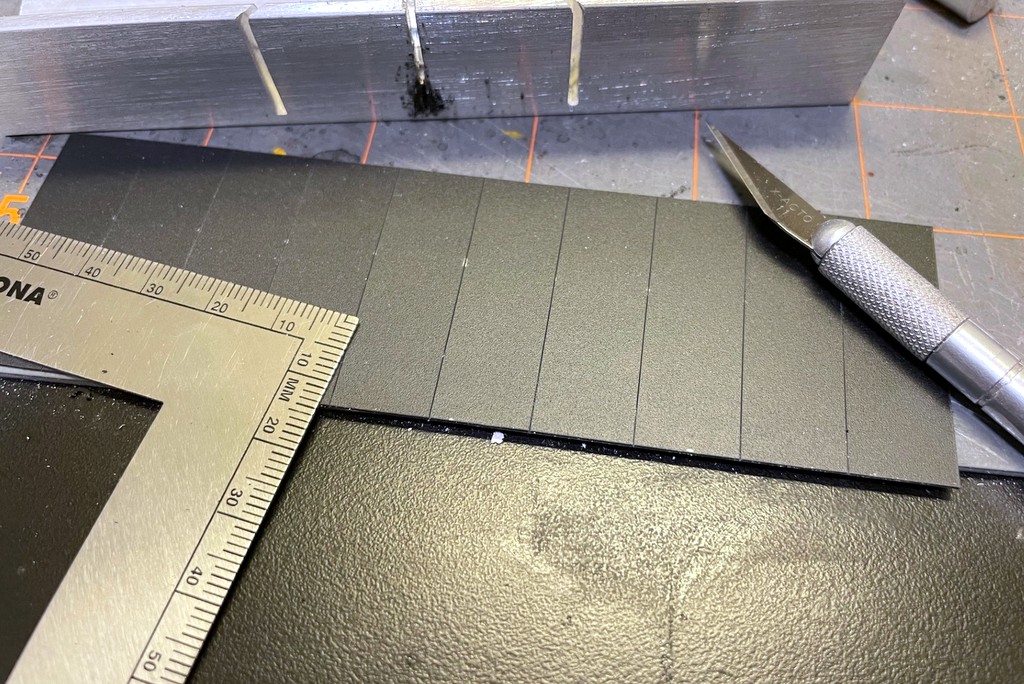
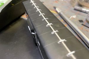
25. The new roof is cut from .010″ black styrene with panel lines scribed into it
26. I cut the roof in half to work around the roofwalf supports
27. After cutting notches for the roofwalk supports and curving the outside edge, I glued the new and old roof edges together
27. After cutting notches for the roofwalk supports and curving the outside edge, I glued the new and old roof edges together
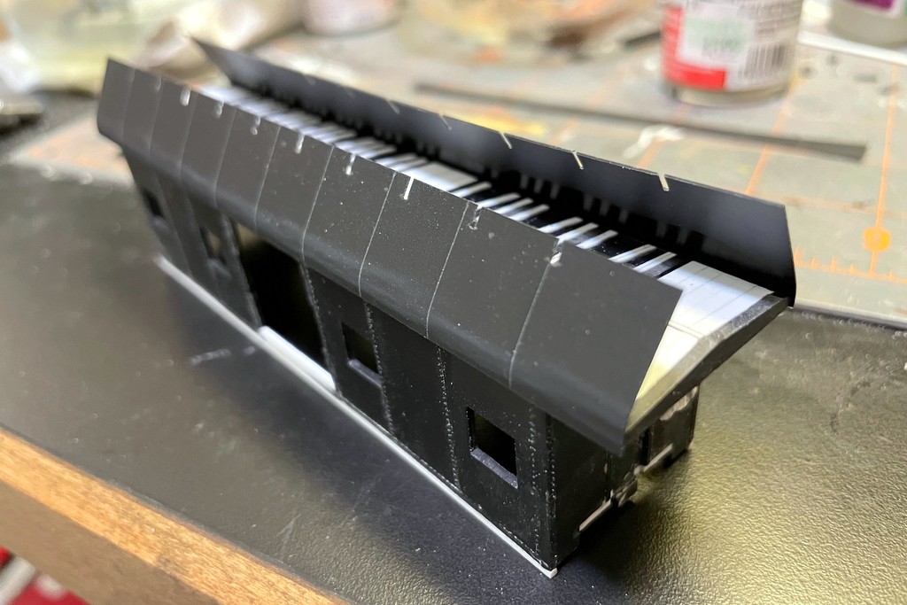
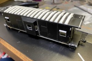
28. I glued the rest of the roof in place
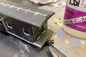
29. Finished round roof with seams filled and sanded
- Holes for corner posts. This is a good point to drill holes for the corner posts in the undersides of the roof using a #79 drill bit. I drilled it as deep as I felt comfortable without poking through the top.


Trucks and End Platforms
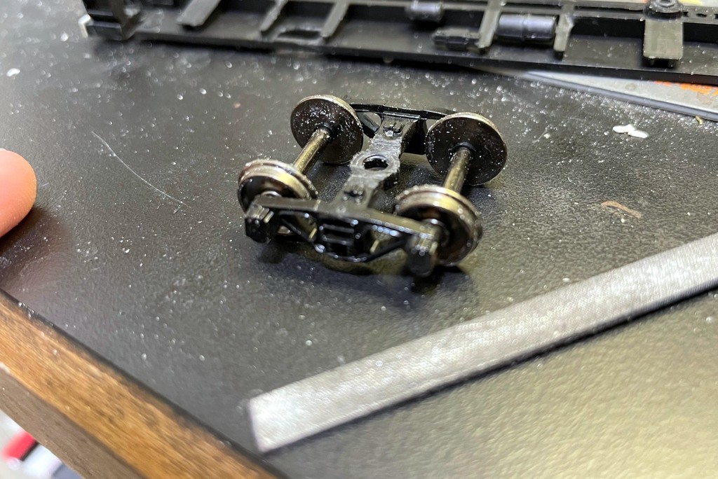
- Trucks. Many of the Southern’s cabs of this era, including the two I chose to model, use Blomberg friction bearing trucks with regular coil springs rather than the leaf springs more common to a caboose. I dug some old Athearn Blomberg friction-bearing trucks that came off a freight car many years ago out of the scrap bin to use for this project, but you can use any similar truck. The first thing I did was remove the plastic wheels and replace them with Reboxx 1.040″ 33″ metal wheels–these aren’t being manufactured any more, but you can still find them second-hand, and they fit much better than Intermountain or other shorter-axle metal wheels. The Southern’s bay window cabs also sat a bit lower than the Southern Pacific prototype for the Athearn car. Since the body dimensions are good, I decided to take this height out of the trucks. I used a flat file and filed down the center mounting hole of the trucks until it was slightly below the level of the crosspiece between the sideframes. This removes about 1/16″ which seemed to be perfect and let me mount the couplers directly underneath the end platforms at the correct height (the reason I was doing the trucks at this step). Beware, at this point the circle that will hold the truck on via the screw head is very thin–I had to repair one truck with a little bit of styrene sheet because part of the circle came loose.

30. Athearn friction bearing freight car trucks with a modified center post
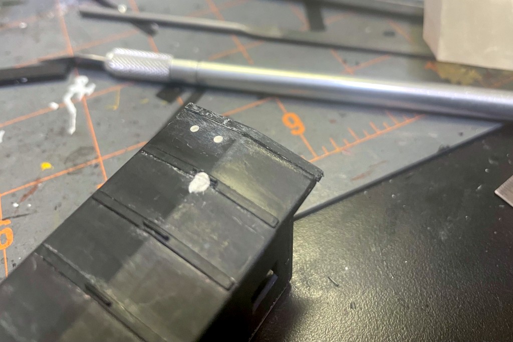
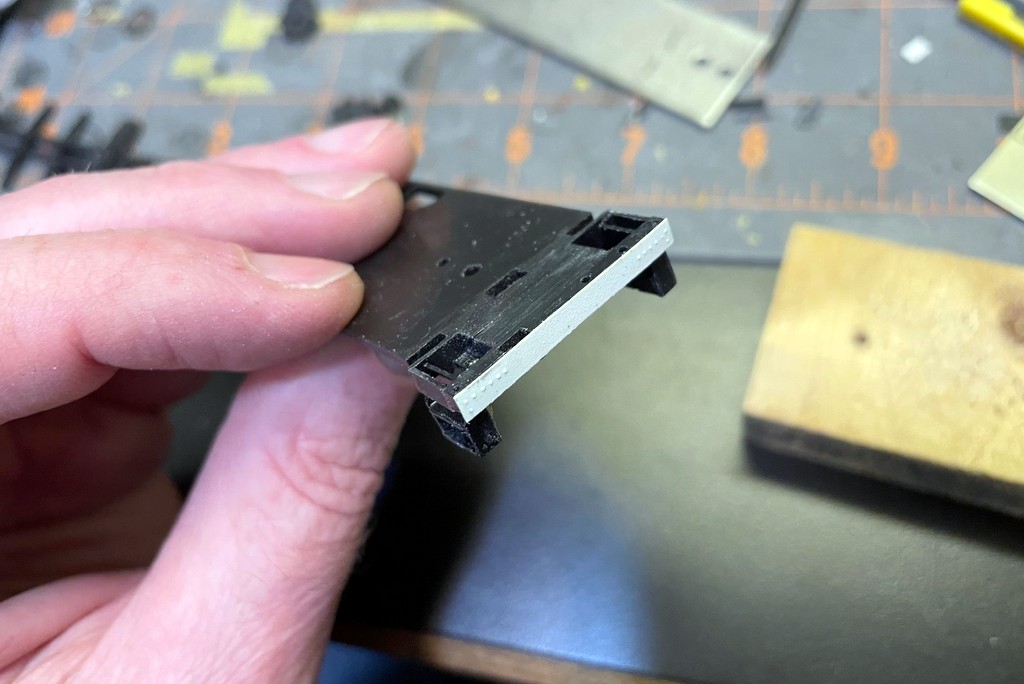
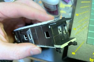
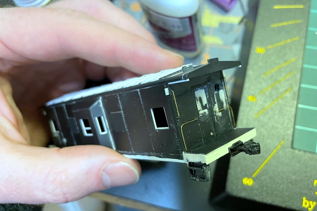
- Detach and reattach end platforms. This was an epiphany for this project! The ends of the Southern caboose are very complicated and involve many pieces stretched from the roof to the end platform. I knew I needed to have the end platforms secure on the body before attempting the ends. However, if I did this before painting, it meant I had no way to insert the windows after painting, so I would have to insert them beforehand and would have no way to to fix one if it came loose or broke… hmm. My solution was to cut the end platforms off of the floor and install them on the body while leaving the rest of the floor and underframe separate. The trick is to cut the underframe a little longer than the floor so it will catch on the end platforms and not let the floor fall into the body–friction keeps it from falling out. Before doing this, I installed the end piece for each platform from a rectangle of .010″ sheet styrene. Using pictures as a guide, I embossed two sets of rivets into the backside using a dull thumbtack on a piece of pine. I secured this piece to the end and let it dry. Next, I installed the factory Athearn weight and marked a line at its edges. I cut along this line with a razor saw and miter box. Next I installed the end platforms onto the body with liquid model cement taking care they dried perpendicular to the body. Once finished, I drilled #79 holes in the corners where the corner posts would go. Now I could finish the ends AND install windows on the interior at the right times for the project.

31. New platform end cap from embossed sheet styrene
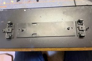
32. I removed the end platforms from the floor on either side of where the weight sits

Bay Windows and Louvers
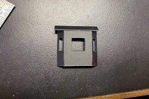
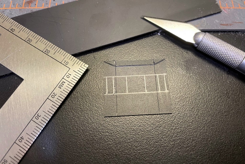
- Scratchbuild bay windows. Rather than try to salvage anything from the Athearn bay windows, I decided to scratchbuild new bay windows. I built each one from a piece of .020″ black sheet styrene. I have an unbuilt resin kit which made it easy to gather dimensions, but a scale drawing will work as well. I drew the three sides, along with the windows, on a single piece, then cut out the windows and along the top and scored the lines between sections with an X-Acto blade. After folding along the lines by pressing the plastic over a metal straightedge, I cut a trapezoidal piece to go inside the bottom of the bay and glued the sides to it. While that glue was still drying, I cut another piece of .020″ styrene for the bay roof larger than needed, sanded one long edge to an angle, and glued it into place with the longest part of the angled side at the extreme top of the bay. While the glue dried, I laid the bays on their backs and worked to align everything, and square things up. A few of the side panels separated from the middle, but these were easily reattached. Once everything is dry, I used an X-Acto blade and flat files to shape the roof. The roof sticks out just a little beyond the sides, so it takes some patience to cut and shape just the right amount. When everything looked good, I attached the bay window to the body, snug against the roof, and patched up the seams with modeler’s putty and sandpaper.

33. Bay window sides and windows drawn onto a sheet of .020″ black styrene
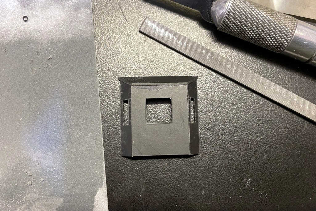
34. Assembled bay window with the rough roof
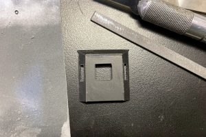
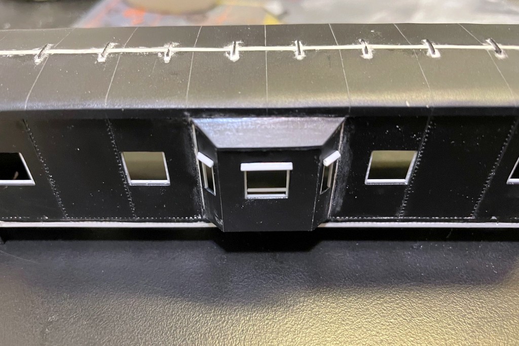
35. Finished bay window
- Build louver doors. One side of the cab has some louvers on a door in the lower left corner. I used a sheet of Detail Associates louvers for this by cutting out a section of louvers sized by pictures and rubbing the back of it on a flat file and coarse sandpaper to thin it down. I cut a door to go around the louvers out of a piece of .010″ styrene with a square in the middle cut to match the louvers. I positioned this assembly on the body using photos and finished it off with a couple bits of .010 x .015″ styrene strip on the top to simulate hinges. Many cabs have a smaller pair of louvers just to the right of this door. I cut and sanded another set of DA louvers and put a notch down the middle to make it two louvers, then positioned this on the body of X2931 using photos. The prototype X3175’s dual louvers are less obvious, so I skipped them but added a fill hatch made from a DA MU cover–the final detail is different from the one in the in-progress pics because it just wouldn’t stick. The DA part allowed me to drill a hole and secure it better.
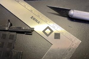
36. The louver and styrene frame
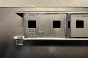
37. Two sets of louvers installed on one side of X2931


Window Details
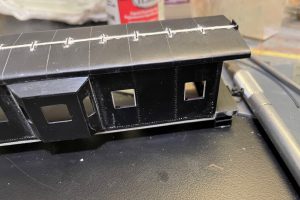
- Fill unneeded windows. This step can really be done any time, but it’s critical to do it before working on the ends. Both windows on each end (door and end) need to be filled, as do the windows that will be blanked out (X3175). I filled mine with .020″ black styrene cut to shape and cleaned up the seams on the end with modeler’s putty and sandpaper. I didn’t bother cleaning up the side windows as these would be covered with blanks anyway.
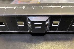
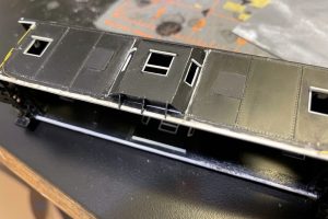
38. Filled window on X3175. This shot also shows the rebuilt roofwalk supports
- Make new porthole window. The Southern-style porthole windows go just above the molded-on window that was just filled. I used photos to align it horizontally between the door and corner. I drilled small hole for the center, then a slightly larger hole, then used a 3/32″ drill bit to ream it out by hand. A little clean up around the edges and that’s it for now. Of note, some Southern cabooses had porthole windows on both sides.

Body Details
- Make new end platform surface. Next comes the new end platforms. These were actually made from anti-skid material on the prototype, but I just used .010″ styrene sheet cut to fit. It’s not quite a rectangle because a small tab needs to fill the space where the door is indented.
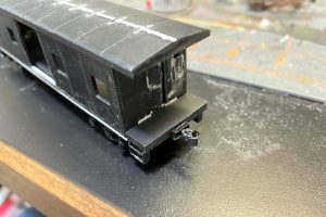
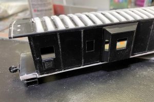
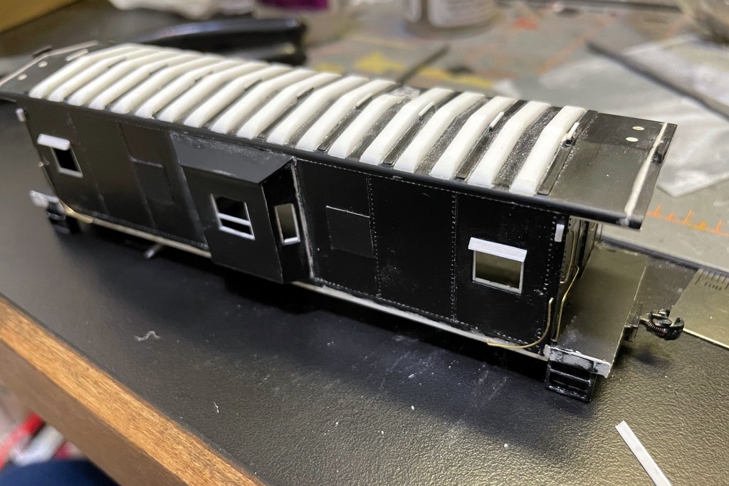
39. Overview of progress on X2931 to this point including the new end platform
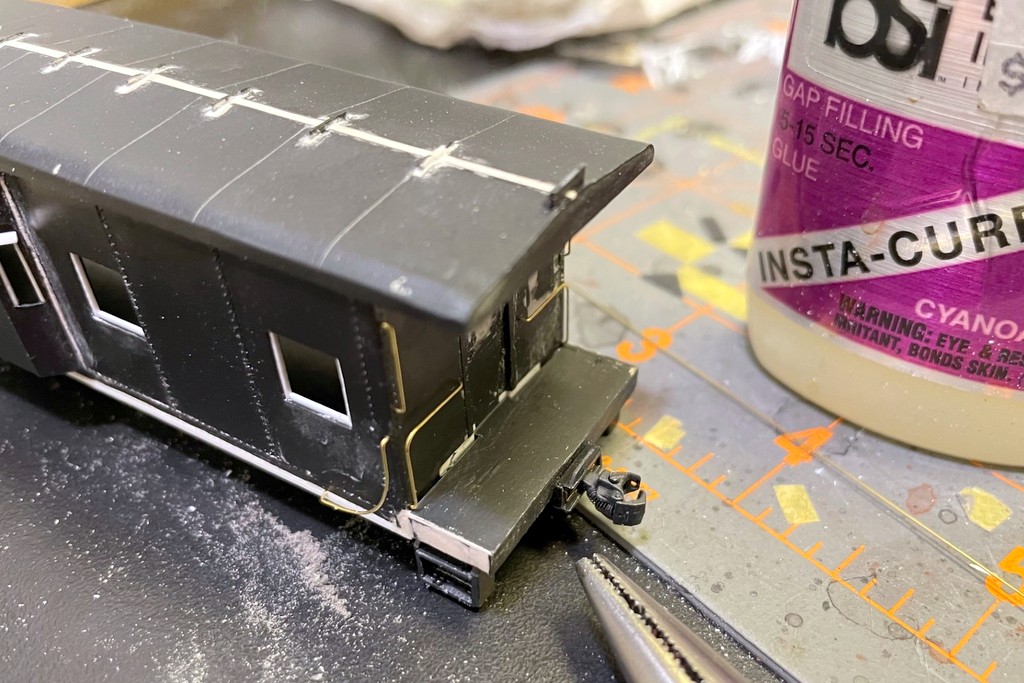
- Add couplers. Because I lowered the trucks, the stock Athearn coupler pockets would now sit too low. Instead, I used Kadee #58 couplers in Kadee rectangular boxes mounted directly to the bottom of the end platform. I had to remove a portion of the end platform cap added earlier to fit around the coupler.
- Add roofwalk supports to the ends. The Athearn model incorporates the end roofwalk supports into the roofwalk, so I had to add new ones. These were made from .020″ styrene cut to fit the roof contour. I placed them just inside the end of the roof on the new extension. I cut them slightly tall and then filed them to match the others once the glue dried.
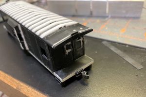
40. End showing the new coupler and roofwalk support
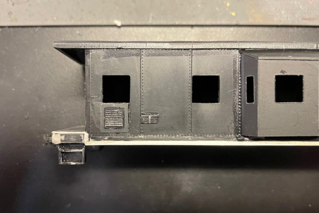
- Add blank window panels. For the blank windows on X3175 only, I cut four pieces of .010″ black sheet styrene the same size (maybe a fuzz larger) than the square windows. I placed these over the smaller windows on the prototype and secured them with liquid model cement–one edge of the blank should be touching the molded on seam. I did the same for the areas where there are no windows, using the existing windows to line things up vertically.
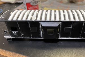
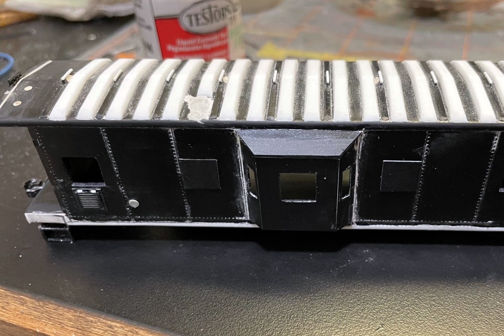
41. A good view of the window blanks on X3175. This view also shows the modified roof panel where the smokestack will go
- Make the window frames. I made my own window frames out of strips of .o15 x .020″ strip styrene. First, I cut the vertical members to fit–they should all be the same, but since the windows were cut by hand, there’s likely to be a little variety. When I installed the vertical pieces, I put the .020″ side against the window edge and let the .015″ (smaller) side show slightly recessed into the body. For the horizontal member, I cut a piece of .015 c .020″ strip styrene to fit snugly between the vertical members. I installed this with the .015″ side against the bottom of the window and the .020″ side showing. I recessed the piece slightly to the backs of the horizontal and vertical pieces are flush and the front looks like it’s in a track made by the vertical members. If you want to model an open window (as I did on my bays), place this member flat against the bottom with the .o20″ side down and make a new crosspiece aligned with the tall side showing at the position you want the window to be open. You can’t see the top horizontal member in photos, so I didn’t model anything here.
42. Windows with the vertical members of the frame inserted

43. Fully framed windows
- Other bits. X3175 had a few extra little bits on the body. Specifically, I added a rectangular block to the upper portion of each corner. These look like holders for marker lamps, but I modeled them with just a scrap of styrene. There are also some horizontal extensions under the roof over the steps which I modeled with bits of styrene–I’m guessing scale 2×3″
44. This view shows a lot of details including the marker holders, bits over the steps, filled end windows and porthole, and some of the end grabs
- Grab Irons. Most Southern cabs have four grabs on each end of the body and four grabs on each side. While commercial parts are available, I bent all my own grabs for this project out of .012″ brass wire. For the vertical end grabs, I used photos as reference for how long these should be, bent the wire with needle-nosed pliers, and made four identical grabs for each caboose. I drilled the holes using a #79 bit and secured them with CA. For the 90-degree grabs, I first bent them around the shaft of a small screwdriver to get the rounded corner, then bent the ends with pliers. For the round grabs on the sides, I first bent the wire around the handle of an X-Acto knife to get the broad curve. Commercial caboose grabs tend to be uniformly rounded and close to 90 degrees of bend, but the Southern’s grabs are more “J” shaped–they’re straight at the top and stop somewhere around 70 degrees on the bend (they’re still facing slightly downward when they reconnect to the body). As mentioned earlier, the original molded-on grabs are mounted too far into the body, so don’t use these as a guide (I did, and I had to refill the holes I’d drilled)–the vertical part of the grab should be attached just inside the side edge, and the round part should connect in the middle of the outermost side window.
45. End grabs are in place. Notice the more “J”-like shape of the corner round grab
- Sunshades. Sunshades are another distinctive feature of pre-1970s Southern bay-window cabs, and they’re easy to add. Some cabs lost their sunshades over the years, so it’s helpful to have a picture of your prototype for this step. There are two sizes, one for the bay windows and one for the side windows. In reality, these shades are thin pieces of metal and hollow inside. Unfortunately, this design yields a weak and easily broken sunshade on a model. Since I never look up into this space, I decided to make the shades solid for strength. For the bay windows, I whittled down a long piece of .030 x .030″ styrene strip by running an X-Acto blade perpendicular down one of the corners repeatedly until the styrene was a triangle shape, then I cut the pieces to length and glued them over the windows. For the side window shades, I filled a piece of .060″ styrene L-shape with modeler’s putty, then sanded the puttied edge smooth once it dried and sealed it with CA. If you’ve got an appropriate piece of square styrene strip, I recommend trying the whittling method first, but the putty method yields good results.
46. The large sunshades go over the side windows
47. The bay window gets smaller sunshades on all windows
48. All sunshades in place on X3175
- Roofwalk support tops. Prototype roofwalk supports generally have a small angle or platform at the top where the roofwalk is attached. I normally don’t model this, but I knew with this model I would need to cut down a metal roofwalk to length, and I wanted a platform on which to join the two pieces. There are 12 total tops on each caboose, and I made 11 tops out of scale 1×4″ styrene strip. For the 12th, I made it out of scale 1×6″ styrene strip. I placed this larger strip on one of the supports just outboard of the bay window on the end where the smokestack will go, 8 from one end and 5 from the other–this is where the seam will be. The smaller tops went on all the other supports.
49. I added top plates to my roofwalk supports–note the larger one just outboard of the bay window for where the 2 roofwalk pieces will come together
- Bay window supports. The final step on the body before moving to the ends was to add the triangular bay window supports. Most Southern cabs of this era had three supports per bay, but some (like X2931) only had two. I cut these to fit from .020″ black styrene sheet and glued them into place with liquid model cement. After they dried, I cleaned them up a little with a file and X-Acto blade.
50. Bay window braces made from .020″ styrene sheet


Now these models are ready for the most challenging part of the build – the ends – which I’ll cover in Part 3.