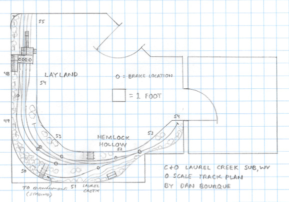
- Size: 14′ x 14′
- Scale: O
- Minimum Radius: 48″
- Minimum Aisle Width: N/A
- Designed by Dan Bourque

Layland, West Virginia lay at the end of the Chesapeake & Ohio’s 6-mile long Laurel Creek Sub that originated at the small yard at Quinnimont, WV on the New River. Like most of the early lines built from the New River, grades were steep (up to 4%), and switchbacks were used to access some of the tipples crammed into the tight hollows.
The Layout
This track plan represents the very end of the Laurel Creek Sub and the medium-sized tipple at Layland, and the track arrangements would work from the 1930s-1970s. The plan is unique in that it fits realistic O-scale operation into a medium-sized bedroom and still leaves space for the room to function as a bedroom or office space.
Layland was accessed via a switchback at Hemlock Hollow with a very short tail track (tail track modeled to scale). There was a small coal loader on a single track just off the switchback, and four tracks that went around a curve and under the tall tipple at Layland, all of which are modeled in this plan. There was some sort of structure, perhaps a foot bridge, that went across the main track from Quinnimont just across from the small loader that is visible in aerial photos, and I’ve used it to disguise where the main goes under the scenery to get to staging, a simple one-track affair under the tipple that represents Quinnimont.
As explained in the “operations” section below, the grades on this layout are critical for both operation and for getting staging to fit under the tipple in a short length of track. The tracks under the tipple are modeled at a prototypical ~1.5% while the tail track and main are modeled closer to 3.5%. Because of the grades, “brakes” (rods that can be extended up through the tracks to hold car axles) are installed in several locations where cars might be spotted. Construction would be simple using open box bench work suspended from the wall and braced with brackets underneath. DCC would be overkill for this layout, but a walk-around throttle would be best.

Operations
Operations on this layout are designed for 1-2 operators operating the Laurel Creek Shifter. Power would be a 2-6-6-2 Mallet or a pair of GP7s or GP9s depending on the era, and the train would consist of 9-12 hoppers and a caboose. While I don’t have details on how this area was worked, I imagine gravity played a very important role, especially in assembling the loads.
The shifter would head out from the Quinnimont staging track and head to Hemlock Hollow. The tail track would likely allow only 1-2 hoppers at a time to be switched from the main to the tipple tracks. The first order would be to gather up the loads at Layland and place them on a single track to clear the tipple for empties. Working back and forth a couple empties at a time, the shifter would fill the tail tracks of both loaders before parking the caboose on one of the load tracks at Layland.
Now comes the fun part. Due to the grades, it makes sense for the shifter to head back to Quinnimont locomotive first to avoid runaway hoppers, but how can that be done with such a short tail track and no good run-arounds? Why gravity, of course! With the locomotives on the main below Hemlock Hollow, 2-3 loads at a time would be coasted down into the tail track where an operator would quickly realign the switch to route toward the main before the hoppers stopped and began coasting back downhill. Several turns would be needed to assemble the train with the locomotives pulling forward to clear the switchback each time. Finally, the cab would be rolled onto the back of the train using the same procedure as the hopper, and the shifter would head back to Quinnimont.
Things I Like About This Plan:
- Realistic O-scale operations in a bedroom
- Ability to model a single scene in great detail
- Use of gravity as part of switching operations (just like prototype operators)
- Simple construction (only 9 switches)
Things I Don’t Like About This Plan:
- Tight radius
- Not much variety in operation
Related Products:


