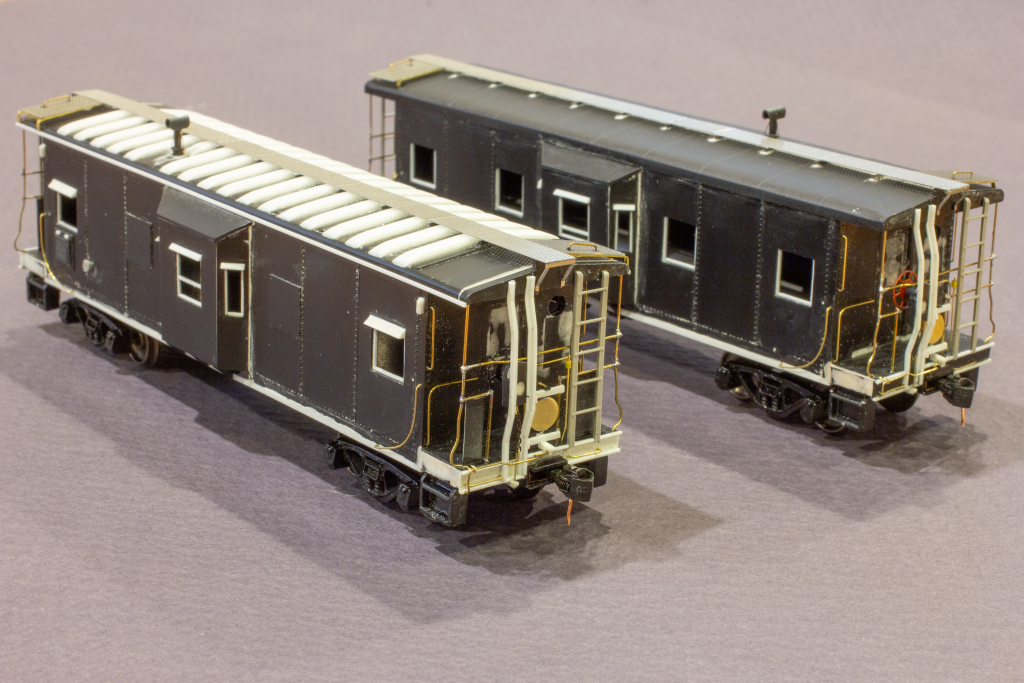
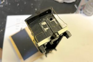
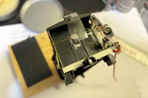
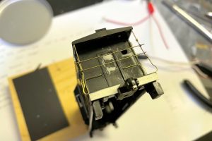
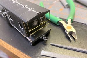
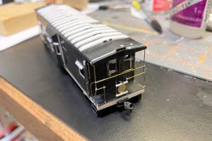
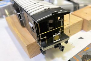
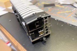
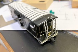
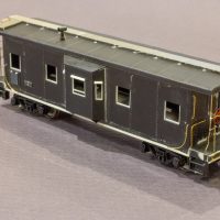
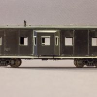
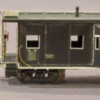
In Part 2, we finished up most of the body details, and in Part 3, we’ll tackle the toughest portion of this model: the ends. Each end contains around 60 individual pieces of styrene, wire, chain, and brass sheet. While it’s incredibly time-consuming to add all the prototypical details, these details are what the caboose really stand out and scream “Southern.” But first, the underbody needs some detail.
Underbody Details
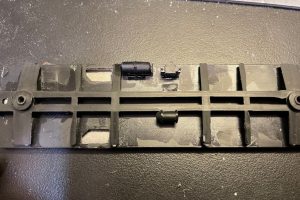
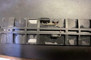
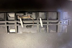
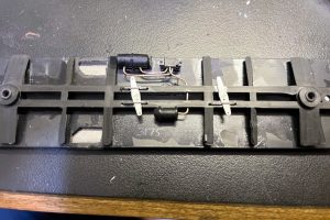
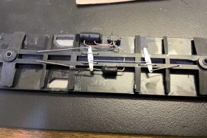
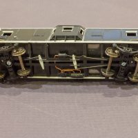
- Move the brake components. As these are “layout models” rather than contest models, I wanted just enough brake gear to present the right silhouette when viewed from the side–as it turns out, that’s most of the brake gear, but it’s not modeled in great detail. The brake cylinder, air reservoir, and triple valve are all molded into the Athearn underbody, but they’re in the wrong spots. The brake cylinder location is acceptable, but I carefully cut the air reservoir and triple valve from the frame and cleaned up any flash or excess plastic. Next, I drilled holes into the air reservoir and triple valve–two into the reservoir and three into a single face of the triple valve. The drill size depends on what you’ll use for piping. I use the copper center of old Cat 5 ethernet cables, so I picked a drill bit slightly larger. I drilled the same size hole through the center beam of the frame behind and even with the brake cylinder. I also drilled a #79 hole into the conical end of the brake cylinder. Next, I glued the components into their new places as shown in pictures based on diagrams and what I could see from the sides in prototype photos. Of note, the air reservoir is more oval than round, so I glued the air reservoir vertically to maximize its profile as seen from the sides. Additionally, the air reservoir should go on the opposite side of the louvers on the cab sides, so make sure when you glue the frame to the floor, it fits into the body in this orientation.
- Add piping. I cut piping from the copper center of old Cat 5 ethernet cables. This material is a good size and very pliable, so I bent two lines to go between the air reservoir and triple valve and glued them into place with CA. Then I snaked a piece of the copper piping from the triple valve, through the frame, and into the rear of the brake cylinder.
- Add brake gear. I created generic brake rigging using the brake gear of a detailed freight car as a guide. I made two arms out of styrene and glued these to the center beam at a slight angle. I made the arm restraints and rods from .015″ steel wire and secured them to the center beam of the frame in a place where they would clear the truck swivel. The toughest part was adding the short piece of Detail Associates chain between the arm adjacent to the brake cylinder and the rod connected to the body (in theory to the brake wheel). I bent some .010″ brass wire into a “J”, threaded it onto the last link of the chain, and crushed it closed with some pliers. I did this on both ends and routed one end to the arm and the other into a hole in the body. I connected the brake cylinder to this arm using a short piece of .015″ steel wire inserted into the hole previously drilled into the brake cylinder cone.
- Floor. One thing I would change… I didn’t bother filling in the holes left by removing the equipment boxes from the floor in part 1 because I wasn’t worried about underbody detail, and the metal weight would cover the holes. In retrospect, it would have been worth it to fill these in with sheet styrene and putty just to avoid having these embarrassing gouges in an otherwise smooth floor.
Wire Crash Bars
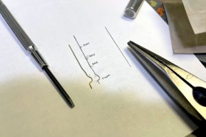
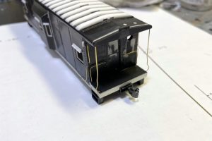
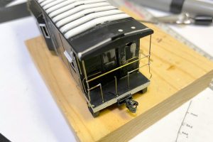
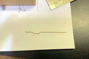
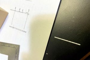
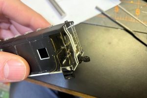
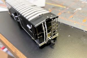
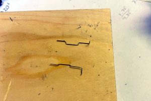
- Bend the corner posts. I started by drawing a scale diagram of a corner post on a sheet of paper. There is a teardrop-shaped loop at the base of the post followed by a slight inward bend below the lowest crossbar. I also marked the locations of the crossbars on the diagram. To bend each post, I started with the loop which I bent around the shaft of a small screwdriver. Then I made the other bends using a pair of pliers and making sure all the bends were in two dimensions only (flatten it as see from the sides). I made four identical posts for each caboose and cut them so about 1/16″ sticks out below the loop, and the top extends about 1/32″ into the roof. I also used a Sharpie to mark the locations of the crossbars. Then I inserted the bottom and slightly bent the bar to get the top of the post into the hole previously drilled into the underside of the roof and secured everything with CA.
- Solder the cross members. The crossbars were initially installed as straight wires across the corner posts for simplicity and to hold the shape. In reality, there’s a bend in the top wire where the brake wheel goes (a new wire later in the process), and there is a break in the lower wire. I secured the top wire first by coating the joints with flux, then securing the crossbar to the body with a piece of tape to hold it in place. To avoid melting the plastic, I placed a couple metal alligator clips on either side of the joint to act as heatsinks. Then I used a soldering iron just hot enough to melt the solder and soldered the joints. I did the same for the lower crossbar. Then I clipped off the excess wire (outside the corner posts) and cleaned up any excess solder with a file.
- Install vertical posts. I installed three vertical posts between the floor and the lower crossbar. Two flank the coupler, and one sits just outside where the brake wheel will go to the left side of the coupler. I just eyeballed their placement based on photos. I drilled a #77 hole in the platform floor and used some .010 x .018″ brass bar for these vertical pieces. I cut the pieces oversized and first secured them to the floor–for some that had trouble staying in place, I used the heat of a soldering iron to slightly melt them into the plastic. Then I soldered the rightmost and leftmost posts to the lower crossbar… that step sounds simple, but it was a real pain in the rear to get everything to line up and sit vertically. Once complete, I cut the lower crossbar inside of these posts and removed a piece of the crossbar between them. I also removed the portion of the vertical supports that protruded above the lower crossbar. Finally, I installed the middle vertical support between the other two and trimmed it to the same height.
Marker Panel
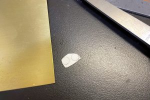
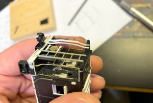
- Make the marker panel. You can save a bit of time and effort if you don’t care to make the marker panel operational, but this was a feature I wanted to have of my models. The marker panels are red on one side and yellow on another. On the prototype, they were used to indicate whether a caboose was marking the end of a train on the mainline (red) or was safely tucked away in a siding (yellow). Since at least one of my cabs would spend half its time safely tucked in a siding with its mine-run power, I wanted to be able to change its marker to yellow. I made the round panel from .005 brass sheet. I placed a white sticker label on the brass and marked the circle with a template–it should be about a scale 18″ in diameter when finished. I cut the circle with scissors, removed the sticker label, and cleaned up the circle with a file.
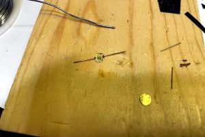
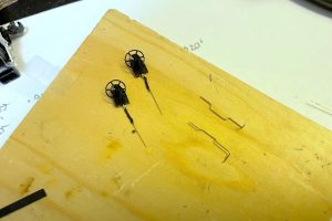
- Solder the marker axle. I created the axle around which the marker would pivot from short pieces of .o15″ brass wire. I soldered these to opposite ends of the disks, overlapping one side by about 1/16″ to give it some strength. A set of “third hand” alligator clips helped tremendously. Once I was happy with the location, overlap, and angle, I filed the excess solder from the wire and disk. Don’t be surprised if you have to redo a joint or two. I made two of these per caboose.
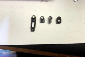
- Create the brackets. Each marker panel needs two brackets. I made two identical brackets from bits of scrap styrene. The crossbars are strip styrene, about .020 x .030″, though I don’t know exactly (scrap bin, right?)–they’re big enough to span the vertical supports flanking the coupler plus a little more. Then I took a piece of .030 x .030″ styrene strip and drilled a #78 hole down into the center. I cut short pieces and glued them to the sides of the crossbars, centered with the hole vertical. I also added a small rectangle of .o10″ black styrene to the top of the block with the hole. Once the glue dried, I continued the hole through the black piece–this way, even if moving the marker scrapes the paint off, it will show black underneath rather than bright white.
- Assemble the marker. To assemble the marker, I first bent one of the axle wires about 45 degrees to the left about the same distance above the disk as the bracket is thick–this would be the handle for turning the marker. Then I inserted this bend through the upper bracket and added the lower bracket underneath, trimming the axle about 1/16″ above the bend and below the bottom bracket.
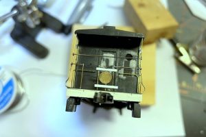
- Install the marker. I put four dots of CA onto the vertical posts approximately where the marker panel would go. I took the entire assembly and placed it onto the vertical posts, carefully positioning it per photos and ensuring it sat correctly. I added extra CA where necessary, and eventually I ended up heating the metal vertical posts to slightly melt the styrene brackets into place–this finally allowed them to be strong enough to handle. Once secure, I trimmed off the excess ends of the brackets and filed them clean–they go just outside the vertical posts.
End Cage Details
- Build the relief valve. On the prototype, there’s a long narrow pipe with a fixture on top that extends from the platform to above the top crossbar between the ladder and the marker panel. I believe this is a relief valve for the brake system, and there’s one on each side. I made an approximation of this pipe using a piece of .o12″ brass wire with a slight bend in the bottom along with a piece of narrow masking tape wrapped around the top to form the fixture. I drilled a #79 hole in the platform and secured it using CA. I also used a drop of CA to secure the masking tape.
- Add safety panels. Many, but not all, of the Southern’s cabs of this era had large safety panels between the lower crossbar and the platform. For X3175, I cut rectangles using photos as a guide (X2931 didn’t have these panels when I modeled it). The rectangles are slightly narrower than the area between the corner post and first vertical post on the left side of the coupler and it goes behind the ladder on the right side. I secured them using CA and liquid modeling cement.
- Install ladders. The ladders are Detail Associates 7-run ladders. I trimmed off the lowest rung to allow the vertical members to extend partially onto the lower end sill of the platform, and I cut the top just below the top of the roof–the inner member is slightly taller than the outer. I gave the top of the ladder a curve inward using a flat file, and I secured the ladder top and bottom using liquid plastic cement.
- Install new upper crossbar. At this point, I was able to replace the temporary upper crossbar with a new one that included the “bend out” for the brake wheel. It’s theoretically possible that I could have installed this from the get go, but as tricky as it was to get the initial bar in the right place, it would have been 10x tougher to get the bend at the right angle. With the ladder on, however, I was able to easily remove the temporary bar, insert the newly bent bar, and use the ladder to hold it snugly against the corner posts while soldering which made it much easier.
- Build brake wheel supports. The Southern’s brake wheel supports are made from cut, bent, and welded L-girder. Rather than mess with L-girder, I decided to make mine from a flat piece of styrene with the L-bracing added on afterward. First, I created a scale drawing of an individual post that included marks for the bends and dots for the rivets at the top, bottom, and at the brake wheel. I then cut strips of scale 1×4″ styrene strip and transcribed the lines and rivet locations onto them. Then I bent them gently at the bend lines using a metal straightedge, and I embossed the rivets using a dull thumbtack to press into the plastic while holding it on top of piece of pine. When I was happy with the shape, I glued it onto the body making sure it was touching (but not stretched over) the bend in the upper crossbar. Like the ladder, the outer vertical member is a little shorter than the inner. Once that dried, I cut individual pieces of the L-bracing for each support out of .015 x .020″ styrene strip (short edge glued down). I used the same drawing as before but cut each piece to fit between bend lines and trimmed them with a slight inward or outward angle depending on which way the bend went. I glued these onto one side of each vertical member and lined them up as best I could while the glue was still pliable. Once everything dried, I was able to clean up with a little filing and sandpaper to get smooth bends. For my prototypes, the L piece was on the outside, but photos some some cabs with the L piece toward the inside of the vertical pieces.
- Build brake wheel housings. For the brake wheel housings, I started with the Athearn brake wheel stands. I filled in the brake wheel hole and filed it smooth once dry. I cut the bottom off each stand and created a backing for the housing using a rectangle of .010″ black styrene sheet. Before gluing this sheet on, I used a small drill bit followed by a hand-turned 1/8″ drill bit to create a hole in each back. When glued on, this simulates the indentation found in the prototype that can be seen between the vertical supports. Once dry, I filed the rectangle to match the contour of the brake housing and filled in the gap above the brake wheel hole. Once sanded smooth, I added the brake chain. I first drilled a #79 hole into the center of the bottom of the housing. I cut a short length of Detail Associates chain, and bend two pieces of .o10″ brass wire into a “J” shape. Once I looped the two Js through the end rings, I bent it closed using pliers and secured it with CA. I laid this assembly out straight to dry and finally inserted one of the Js into the brake housing. I drilled a hole into the brake wheel hole (now filled with putty) just large enough to fit a Kadee Miner brakewheel which I secured with CA.
End Sill Details
- Add horizontal pieces. There are horizontal bars that go across the top and bottom of the end sill that make the whole piece a shallow channel. Now that the ladders and brake wheel supports were in place, I filled in the rest of the top edge of the end platform bottom sill with bits of custom cut .015 x .020″ styrene strip. I did the same with the bottom, leaving a small gap between the vertical brake wheel supports where the chain and rod would go.
- Add grab irons. I bent my own grab irons out of .012″ brass wire as commercially available grabs are either too short (18″) or too long (24″). I bent mine about a scale 20-22″, drilled #79 holes, and secured them with CA. They are not symmetrical–the right side goes below the ladder, and the left side goes between the outboard brake wheel support and the end.
- Add bracket for train air hose. I make my own train air hoses from copper insides of old Cat 5 ethernet cable, the same material I used for the brake piping. To secure it, I used a small piece of channel styrene (from the scrap bin) about 3/16″ long mounted in the angle between the coupler pocket and the bottom edge of the end sill on the right side of the coupler. I didn’t install the air hose just yet.
- Add brake elbow. This is the piece that connects the vertical portion of the brake wheel chain and rod to the rods on the underside of the car (not on the model, but on the prototype). I cut a piece of .030 x .030″ styrene strip about 3/16″ long and drilled a #79 hole through one end. I rounded one corner with a file. To mount it, I created a firm base using bits of styrene mounted alongside the left side of the coupler pocket under the platform, just high enough to clear the bottom of the end sill. Then I mounted the elbow onto this platform and extended it out between the brake wheel supports so the hole was showing upward and the rounded part downward.
- Add coupler cut lever brackets. On later rebuilt cabs, the Southern used standard cut levers like the Detail Associates cut bars. However, on earlier cabs, the cut lever was mounted above the coupler, so I ended up scratchbuilding this feature. For the brackets, I drilled a #79 hole into a piece of .030 x .030″ styrene and mounted this to a short piece of styrene (perhaps a scale 2×4″ strip). I glued this to the end platform under the marker panel and over the center of the coupler with the hole piece underneath and facing sideways. For the outboard bracket, I drilled a #79 hole near the corner post, bent an eye bolt (I make mine out of wire, but any wire eye bolt will do), and mounted it with CA in the hole to extend over the end.
- Add brake wheel assembly. It was now time to attach the brake wheel assemblies to the supports. This step was a bit tricky because the brake wheel housing needs to be attached onto the back sides of the supports, and the chain and rod must be extended between the supports to the outside of the end and through the elbow. I found it worked well to put liquid plastic cement onto the vertical supports first, then drop the chain through the supports before placing the housing onto the vertical supports. Once I was happy with the placement, I secured it with more glue, then used pliers to work the chain and rod into the elbow and secure it with CA.
- Bend and secure coupler cut bars. I bent the coupler cut bars out of .010″ brass wire. They’re tricky because there’s a round hand-hold at the lower corner and a bend that goes around the brake. When I was happy with the shape, I inserted these through the eye bolt and styrene brackets and secured things with CA.
Roof Details
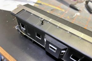
- Cut the walkway. The prototypes (at least the two I modeled) used Morton-pattern roofwalks. I wanted to use a Plano metal roofwalk, but they don’t make them in this length. Instead I used a 40′ boxcar roofwalk and cut it to length. Remember the single extra-wide roofwalk support top we added in Part 2? Using that as a guide, I laid the roofwalk in place leaving a little to hang off one end and marked the existing roofwalk joint that corresponded to the extra-wide roofwalk support top. I used a pair of scissors to cut the roofwalk at this joint line. Next, I held the short half of the roofwalk onto the model so the end would hang off the same as the other end and marked with pencil the line of Morton dots that corresponded to where the two roofwalk pieces overlapped. I cut along this line and filed until the two pieces created a roofwalk of the correct length. I used some modeler’s putty to fill in some of the holes along the new cut edge to make it look more like the finished edge and filed this flush when dry, using a drill bit to open up any inadvertently covered holes.
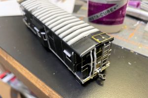
- Add end platform supports. The Plano kit includes a set of brass rectangular braces for each end platform. I bent the outside legs downward using a pair of pliers. For the roof style of X3175, the legs mount into the side of the roof. For the round roof, the legs mount into the top of the roof. Because of this, I bent the legs for X3175 a bit longer, drilled holes into the side of the roof for the small mounting pins, and bent the opposite end of the platform downward at a slight angle to match where the roofwalk would go (the end plaform slopes while the roofwalk does not). For X2931, I bent the legs a little shorter, drilled holes into the roof, and bent the opposite end of the platform like I did for X3175, only it was in a slightly different spot.
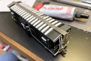
- Add walkways. At this point, I went ahead and added the walkways. I applied a little bit of Pliobond cement to each roofwalk support using a toothpick and gently pressed the walkway pieces onto the supports, being careful to line up the joint on the extra-wide support. Pliobond makes some strings, but they’re easy to clean up once they dry, and the joint stays pliable unlike CA that will pop loose due to the different expansion rates between plastic and metal. My friend Stuart Thayer taught me this trick, and I am very grateful!
- Trim and add end platforms. At this point, I test fit the end platforms on top of their brackets, and they were too long–a bay window caboose roof is narrower than most boxcars. As I did with the roofwalk, I marked the line of dots where I wanted to cut, cut them with scissors, and cleaned up the edge with a file. I mounted the platforms using Pliobond with the cut edge against the roofwalk.
- Add end brackets. The Plano kit also includes some metal end braces. I bent these to an appropriate shape based on the overhang of the roofwalk. I found that for X3175, I ended up mounting the bottom of the brackets to the underside of the roof end. For X2931 (round roof), I drilled holes in the end near the bottom and mounted the bracket pins there using CA on the bottom and Pliobond on the top.
- Add grab irons. The final walkway step was to add a grab iron on the platform over each ladder. The commercial 18″ grabs didn’t seem to fit the hole pattern, so I ended up making grabs slightly longer than 18″ to fit the holes out of .012″ brass wire.
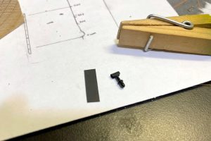
- Make smokestack. The Southern smokestack is a pretty stubby affair with a larger section at the bottom, short stack, and a cover that looks like an inverted U-shaped channel. I decided to make my own out of the parts in the scrap bin which included a couple of old smokestacks from MDC kits as these have the wider base (the Athearn base is narrow). I chopped the stack to length using photos as a guide, and I filed flat notches into the sides of the top of the stack. Next I took a piece of .010″ black styrene sheet, cut it to about the right width for the upper piece, and slowly worked the center of it over a metal edge until it was very pliable and easy to curve back on itself. I trimmed this until it looked to be about the right size when bent over the stack and glued it in place with liquid model cement. I found a clothespin with the spring reversed so the pointy ends form the clamp worked well to hold it in place until it dried. Then I used a file and X-Acto blade to clean everything up. Finally, I drilled a #80 hole through the stack just below the new cover for the support wire.
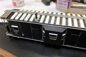
- Mount smokestack. I looked at many pictures and drawings, and when I was satisfied I had the right spot, I drilled a hole for the smokestack and test fit the stack. Of note, the smokestack goes on the same side as the louvers. I took a piece of .006″ wire and glued it into the hole in the smokestack with enough hanging out the ends to reach beyond the bottom of the stack. Then I drilled #80 holes into the body on either side of the smokestack hole using pictures as a guide for placement. Finally, I bent the wire downward, inserted the wire into the smaller holes, mounted the stack into the large hole, and secured everything with a combination of CA and liquid plastic cement.
Final Details
- Add little rectangles. I have no idea what these are (toilet-related?), but Southern cabs of this era had small rectangles under one side. It could be on either side, so I used photos for reference. I just cut two pieces of .020″ styrene into rectangles, glued them back-to-back, and glued them to the bottom of the body at a slight outward angle to approximate this detail.
- Add train air hose. I waited until the end to install these because they tend to break off with handling. Using the copper core of an old Cat 5 ethernet cable, I bent a piece to resemble an air hose and used a Detail Associates part as a model for where to bend. I used needle-nosed pliers to crimp the ends into something resembling a gladhand and secured the air hose into the channel bracket installed earlier with CA. To complete this, I added a second piece of styrene channel about 1/16″ long under the first piece and glued them using liquid model cement. In the end, this creates a fairly indestructible air hose–it may not be as detailed as a plastic part, but it looks good and won’t break off… I got tired of finding my right-of-way littered with air hoses on my last layout.
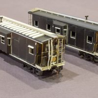
- Southern bay-window cabs ready for paint and showing the bulk of the modeling work
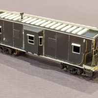
- 3/4 view of X3175 before paint
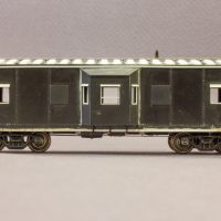
- Side view of X3175 before paint
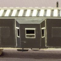
- Bay window details of X3175 before paint
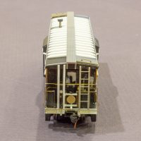
- End details and roof profile of X3175
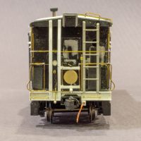
- End details including the working marker panel
- Underbelly of X3175… in retrospect, I would have filled the holes in the floor left by removing the equipment boxes
- 3/4 view of X2931 before paint
- Side view of X2931 before paint
- Louver details on X2931
At this point, the models are all ready for paint which I’ll cover in the final part of this series.


